US4383563A - Golf bag - Google Patents

Golf bag Download PDF

Info

Publication number
US4383563A
US4383563A US06/287,626 US28762681A US4383563A US 4383563 A US4383563 A US 4383563A US 28762681 A US28762681 A US 28762681A US 4383563 A US4383563 A US 4383563A
Authority
US
United States
Prior art keywords
golf bag
bag
golf
deck
cradles
Prior art date
Legal status (The legal status is an assumption and is not a legal conclusion. Google has not performed a legal analysis and makes no representation as to the accuracy of the status listed.)
Expired - Lifetime
Application number
US06/287,626
Inventor
Christian H. Kirchhoff, Jr.
Current Assignee (The listed assignees may be inaccurate. Google has not performed a legal analysis and makes no representation or warranty as to the accuracy of the list.)
Individual
Original Assignee
Individual
Priority date (The priority date is an assumption and is not a legal conclusion. Google has not performed a legal analysis and makes no representation as to the accuracy of the date listed.)
Filing date
Publication date
Application filed by Individual filed Critical Individual
Priority to US06/287,626 priority Critical patent/US4383563A/en
Priority to EP82106423A priority patent/EP0071115A3/en
Application granted granted Critical
Publication of US4383563A publication Critical patent/US4383563A/en
Anticipated expiration legal-status Critical
Expired - Lifetime legal-status Critical Current

Links

Images

Classifications

    • AHUMAN NECESSITIES
    • A63SPORTS; GAMES; AMUSEMENTS
    • A63BAPPARATUS FOR PHYSICAL TRAINING, GYMNASTICS, SWIMMING, CLIMBING, OR FENCING; BALL GAMES; TRAINING EQUIPMENT
    • A63B55/00Bags for golf clubs; Stands for golf clubs for use on the course; Wheeled carriers specially adapted for golf bags
    • A63B55/404Covers or hoods for golf bags
    • A63B55/406Covers or hoods for golf bags releasably attached

Definitions

  • First is the lightweight bag, meant to be transported in hand or over the shoulder principally by a walking golfer.
  • a principal design objective is to offer a bag that adds as little as possible to the weight of the barest essentials: a single sleeve for clubs, and usually a pocket for balls, tees, scorecard and pencil. Often the clubs are merely jumbled together with, at most, a crossbar at the bag mouth to separate the woods from the irons.
  • Second is the full service bag for the professional golfer, the travelling golfer and the golfer who principally uses a caddy or cart to transport it.
  • weight is less a consideration
  • expense is less a consideration and having everything at hand that the golfer may need or want is much more important.
  • the present invention provides a full service golf bag which also is suitable for off-the-course transport and handling as baggage without the need for a separate rigid enclosing case, and which obviates the need for mittens for the club heads.
  • the full service golf bag includes a rigid body with a separate tube for the shaft of each club and a deck with cradles shaped to fit the respective club heads.
  • the tubes are shaped to frictionally retain the clubs by their handgrips.
  • An adjustable retainer clip for the putter is shown, as are specially designed compartments for all usual golfing accessories such as shoes, rake/retriever, thermos, umbrella, towel, balls and the like.
  • a rigid, removable cover is provided over the upper end of the bag body.
  • the lower end may include a rotatable base further provided with rollers useful for rolling the bag along airport concourses and the like.
  • FIG. 1 is a perspective view of a golf bag provided in accordance with principles of the present invention, with the cover exploded therefrom to expose the upper end of the bag body;
  • FIG. 2 is an opposite-side perspective view showing the cover in place
  • FIG. 3 is a longitudinal cross-sectional view thereof
  • FIG. 4 is a larger scale fragmentary elevational view of the shoe storage region, partly broken away and sectioned;
  • FIG. 5 is a top plan view of the bag body
  • FIG. 6 is an enlarge-scale fragmentary perspective view showing the putter mounting clip
  • FIG. 7 is a bottom plan view of the bag body
  • FIG. 8 is an enlarged scale fragementary cross-sectional view taken on line 8--8 of FIG. 7.
  • the golf bag 10 includes a body 12 and a cover 14. These parts are preferably molded of the same kinds of semi-rigid, tough synthetic plastic material that is used in the manufacture of plastic airline luggage, portable TV cabinets, automobile body parts and the like, and using the same molding techniques.
  • the body 12 includes a perimetrical sidewall 16 of generally rounded-rectangular plan figure, a bottom wall 18 and a top wall 20.
  • a perimetrical sidewall 16 of generally rounded-rectangular plan figure
  • the broader sides of the body are herein designated the front, 22, and the back 24.
  • the two narrower sides are herein designated the handle end, 26, and the towel end, 28.
  • the top wall 20 is shown provided with a horseshoe-shaped outer portion 30, bordering the front and rear sides and the towel end, and with a raised center portion 32 bordering the handle end wall 26.
  • This center portion 32 is stepped-up at 34 from the level of the outer portion 30 by approximately the amount that the shaft of the typical longest-shafted wood is longer than the shaft of the typical longest-shafted iron.
  • the upper, inner side of the bottom wall 18 is shown provided with a plurality of upwardly opening socket-like fixtures 36.
  • the top wall 20 is shown provided with a corresponding plurality of similarly arranged openings 38.
  • a respective tube 40 extends between each fixture 36 and each opening 38.
  • the walls 18 and 20 and the tubes 40 would all be integrally molded together, perhaps even with some or all of the bag body, but in other instances these parts would be separately molded, then fabricated together e.g. by solvent welding, thermal bonding, adhesive bonding or the like. Fabrication of separately formed parts permits the tubes 40 to form as an extrusion that is cut to length.
  • tubes 40 are longitudinally ribbed so as to be corrugated as seen in transverse cross-section, and radially resilient in order to frictionally resiliently hold the handgrips of the respective clubs received therein, as are the fixtures 36.
  • the space 42 within the body but outside the tubes 40 may be left empty or may be filled, e.g. with a foamed in situ mechanical shock-cushioning plastic polymer.
  • the tubes 40 may be formed as an integral, non-foamed skin on such material.
  • the top wall 20 is shown provided with overlay means, in the form of one or more sculptured blocks 44 e.g. made of integrally-skinned semi-rigid foamed plastic resin or a hollow molded shell of plastic material similar to that used in the manufacture of the sidewall 16.
  • overlay means in the form of one or more sculptured blocks 44 e.g. made of integrally-skinned semi-rigid foamed plastic resin or a hollow molded shell of plastic material similar to that used in the manufacture of the sidewall 16.
  • the block 44 Directly over and perimetrically in the vicinity of each opening 38 in the top wall 20, the block 44 is either missing, or provided with a matching opening 46 or provided with a slot or somewhat funnel-like or otherwise guiding surface 48, leading down to a matching opening 46.
  • each tube 40 that is to receive the handgrip and shaft of an iron or wood that the respective guiding surface 48 constitute a cradle which is particularly shaped to permit the inverted top of the respective club head to nestle therein to a depth of, for instance, approximately one-quarter or so of the height of the respective club head.
  • Each cradle 48 regardless of its specific shape is designed not only to nestle a specific club head, but to accept the club head only when the respective club is guidingly homed thereinto or thereagainst so as to have a pre-selected angular orientation. As shown, it is preferred that the cradles 48 orient the clubs so that the woods, W1-W4, which are received in the single row of four cradles 48 which row runs parallel to the long sides of the top wall, down the center of the raised center portion 32, have their faces F at least generally parallel to one another with the heads of adjoining woods being rotated 180° relative to one another, e.g.
  • the cradles 48 dispose the faces F in a set of at least generally parallel planes which lie at approximately 45° to the sides of the bag top wall.
  • five of the cradles 48 are provided at least approximately in a row on that leg of the outer portion 30 of the top wall 20 which lies between the raised center portion 32 and the back wall 24, this row extending at least generally parallel to those structures and having its five cradles 48 shaped to receive, in order, the five lowest-numbered irons, here designated I1-I5, with the longest-dimensioned axis of each club head oriented to project obliquely outwards, away from the adjoining row of woods, along planes parallel to those of the faces of the woods W1-W4.
  • the remaining four of the cradles 48 are provided at least approximately in a row on the opposite leg of the outer portion 30 of the top wall 20, this row extending at least generally parallel to the other two and having its four cradles 48 shaped to receive, in order, the four highest-numbered irons, here designated I6-I9, with the longest-dimensioned axis of each club head oriented to project obliquely outwards, away from the adjoining woods W1-W4, along planes parallel to those of the faces of the woods.
  • This preference clearly is not a slavish one; note that the cradle for the head of club I6 is oriented to point the club head more toward the handle end wall of the bag body (in order to avoid interference with another feature).
  • the preference for forming the block or blocks 44 separately, then adhering or otherwise securing it or them in place upon the wall 20 is to facilitate mass manufacture, it being thereby possible to make the same basic bag 10 in larger quantities, and to customize it to accept the club heads of each particular golfer by making the block(s) 44 to order, or in a range of different styles.
  • a middle way would be to mold-in cradles for the woods W1-W4, but provide a sculpture block or blocks for cradling the irons I1-I9.
  • the deck of the bag 10 may include additional openings which provide the mouths for additional sockets, tubes, wells or the like. Three are illustrated, being openings 50, 52 and 54, respectively for removably receiving a conventional rake/ball retriever tool R, an umbrella U, and a putter P.
  • Each respective tube 56 has an open upper end mounted to the deck perimetrically of the respective opening, and a lower end fixed to the bottom wall 18.
  • any or all of the tubes 40, 56 may be supported at a level above their lower ends, instead of or in addition to being supported at their lower ends, e.g. by passing through an apertured plate (not shown) mounted at an intermediate level in the bag body.
  • any or all of the tubes 56 may be provided with interior grippers such as corrugations 58 for frictionally gripping the element R, U or P removably received therein.
  • the well 54/56 for the putter P is shown provided with an adjustable securement assembly 60 for releasably gripping the throat of the shaft of the putter P.
  • the assembly 60 includes a bracket 62 adapted to be mounted to the bag sidewall 16 at the desired height e.g. by installing nut and bolt assemblies 64 through selectively aligned openings 66, 68 in the bracket 62 and bag sidewall 16 (and respective tube 56, if necessary).
  • a universal joint ball 70 is based on the bracket 62.
  • a universal joint socket 72 is mounted on the ball 70.
  • a clip 74 is mounted on the socket 72 via a fixture 76 which, if tightened via the knurled collar 78 fixes the socket 72 to the ball 70, but which, if loosened, permits the socket 72 to be swiveled on the ball 70.
  • the bracket 62 is placed at an acceptable height and is secured in place using the fasteners 64, then the socket 72 is swiveled on the ball 70 until the clip 74 is disposed at the proper place at the mouth of the well 54/56 to receive the throat of the putter P. Then the collar 78 is tightened to lock-in this position.
  • the putter may be easily slid into the well 54/56 and its throat frictionally laterally urged into the clip 74 for dispositioning the putter head in view for ready access. Removal of the putter is accomplished by grasping its head, urging the throat laterally out of the clip and longitudinally withdrawing the putter upwards out of the well 54/56.
  • the well for the putter could be made more similar to the wells for the other club, with the adjustable securement assembly being replaced by a respective cradle similar to the cradles 48.
  • others of the wells could be provided with adjustable securement assemblies in lieu of cradles, if desired.
  • the cover 14 preferably is molded as an integral member of the same material as the body 12. It includes an end wall 80 and a perimetrical skirt 82. Toggle fasteners 84, such as are used to fasten the halves of luggage shells to one another are provided between the cover skirt 82 and the body sidewall 16 at a level near the top wall 20 where the cover, when in place, skirts the body sidewall. Accordingly, by preference, the cover 14 may be entirely removed by unfastening the toggle fasteners 84. When in place, the cover 14 completely encloses the deck and thus covers over all of the club heads and tools which are exposed on the deck. In order to further protect the clubs and tools in transit, the cover 14 preferably is provided with a liner 86 of resilient foamed plastic material, e.g. of the type conventionally used for cushioning camera equipment in the carrying cases of professional photographers.
  • the body 12 includes a base 88 in the form of a turntable 90 mounted to the bottom wall 18 via a turntable bearing assembly 92, which may be of a conventional type used in the manufacture of swivel furniture (bearing balls trapped between two ring-shaped races respectively fixed to the turntable and to the bag bottom wall.
  • a turntable bearing assembly 92 which may be of a conventional type used in the manufacture of swivel furniture (bearing balls trapped between two ring-shaped races respectively fixed to the turntable and to the bag bottom wall.
  • the bottom of the turntable plate is provided with a plurality of semi-recessed castors 94, preferably of the same ball-transfer type that is conventionally used to the bottoms of luggage (and for the same purpose: to facilitate baggage transfer along airport concourses and the like, by permitting the transferor to roll the bag along on its castors).
  • the castors 94 are preferably equipped with removable caps 96 which, as shown, may be hinged to the bottom of the turntable at 98 and adapted to be received in recesses 100 when not in use.
  • the caps 96 are readily folded about their hinges 98 and snapped in place covering the respective castors 94.
  • the handle end wall 26 of the bag body is shown provided with a shoulder strap 102 and a hand grip 104.
  • Either may be molded integrally with the bag body and either may be provided in any other well-known manner, e.g. of leather or of fabric webbing connected by D-rings to anchors provided on the wall 26.
  • the presently preferred hand grip 104 is integrally molded so as to have anatomically conforming surfaces e.g. as illustrated at 106.
  • the towel end wall 28 of the bag body is shown provided generally in its upper half, with a vertically long, horizontally narrow recess 108. At the top of the recess 108, the wall 28 is provided with a mounting ring for a golfer's towel T and about two-thirds of the way down from the top of the recess 108, the wall 28 is provided, within the recess, with a loop-shaped retainer 110, through which the lower portion of the towel may be pulled when not in use.
  • the loop 110 functions in much the way that a tieback for window drapes releasably keeps them back out of the way.
  • the front wall 22 of the sidewall 16 is shown provided with three accessory features that are discretely located in serially, axially spaced relation along the median of the front wall 22. From the top, these features include a bay-window-like compartment 112 with a horizontally slidable tambour door 114 on the front and a snap-open, snap-closed, hinged lid 116.
  • the internal wall 118 of this compartment is shown in FIG. 3, from which it will be seen that the inner, approximately half of the volume of this compartment and its wall 118 take up a portion of the space within the bag body that lies outside the various tubes and wells for clubs and tools.
  • a vertically-oriented cylindrical compartment 120 sized and shaped to receive a Thermos jug J or the like.
  • the internal wall 122 thereof includes a shelf 124 and the resulting well is closed by a complementarily semi-cylindrical snap-closed door 126.
  • a shoe storage compartment 128 having an internal wall 130 and a bin-type front member 132.
  • the latter is pivotally mounted in the recess defined by the internal wall 130 to pivot about a horizontal axis near its lower edge, between a closed position wherein the front wall 134 is more nearly flush with the golf bag body front wall 22, and an open position, in which its upper end is particularly tilted out so that access may be gained to the shoe storage compartment that is defined between the inner face of the front wall 134 and the internal wall 130.
  • the access door 132 may be provided with a friction fit for retaining it in the open and closed position in which it is placed, and/or it may be provided with securement means such as a snap fastener or the like (not shown in detail).
  • the front member 132 may be removably mounted to the bag body so that when the front member 132 is tilted out it may be entirely removed in much the same way that a desk drawer can be conventionally removed from a desk by fully opening it, then performing an auxiliary maneuver, such as tilting to a different angle and pulling some more.
  • the front member includes means for removably securing thereto the golfer's shoes S which may be carried in the compartment 128.
  • These means are shown including two opposed pairs of spring-urged plungers 136.
  • the plungers pairs are arranged to each frictionally grip a shoe laterally between them by resiliently, opposingly engaging it e.g. between vamp and sole at about the narrowest part.
  • the front member 132 further includes an internal ledge 138 on which the shoes S rest, toe-down, when received in the compartment 128.
  • the back wall 24 of the bag body sidewall 16 is shown including compartments 140 and 142 which may be respectively similar to the compartments 112 and 120, although possibly differently oriented, sized and/or proportioned.
  • the internal walls of all the compartments may be integrally molded with the bag body sidewall, or may be separately molded, and fabricated into appropriately corresponding openings molded or cut into the bag body sidewall.
  • the various compartment doors may be integrally hinged to frames mounted to the sidewall perimetrically of the various compartment recesses, or may be otherwise hinged or mounted for opening, closing, and for securement in a closed condition. Where necessary or desired, locks may be provided against all access to the bag contents via compartment doors and cover.

Abstract

The full service golf bag includes a rigid body with a separate tube for the shaft of each club and a deck with cradles shaped to fit the respective club heads. The tubes are shaped to frictionally retain the clubs by their handgrips. An adjustable retainer clip for the putter is shown, as are specially designed compartments for all usual golfing accessories such as shoes, rake/retriever, thermos, umbrella, towel, balls and the like. A rigid, removable cover is provided over the upper end of the bag body. The lower end may include a rotatable base further provided with rollers useful for rolling the bag along airport concourses and the like.

Description

BACKGROUND OF THE INVENTION
Golf bags fall into two basic types that are designed on correspondingly different principles.
First is the lightweight bag, meant to be transported in hand or over the shoulder principally by a walking golfer. A principal design objective is to offer a bag that adds as little as possible to the weight of the barest essentials: a single sleeve for clubs, and usually a pocket for balls, tees, scorecard and pencil. Often the clubs are merely jumbled together with, at most, a crossbar at the bag mouth to separate the woods from the irons.
Second is the full service bag for the professional golfer, the travelling golfer and the golfer who principally uses a caddy or cart to transport it. Here, weight is less a consideration, expense is less a consideration and having everything at hand that the golfer may need or want is much more important.
Golfers who travel with their equipment by plane a lot are a special consideration, for they require a bag which can be subjected to rough treatment by baggage handlers that can be expected occasionally under the circumstances. Accordingly, some professional golfers heretofore have required a separate travelling case for completely enclosing their bag for off-the-course transport.
Further, no bag heretofore available has provided all the comforts a serious golfer could imagine.
SUMMARY OF THE INVENTION
The present invention provides a full service golf bag which also is suitable for off-the-course transport and handling as baggage without the need for a separate rigid enclosing case, and which obviates the need for mittens for the club heads.
The full service golf bag includes a rigid body with a separate tube for the shaft of each club and a deck with cradles shaped to fit the respective club heads. The tubes are shaped to frictionally retain the clubs by their handgrips. An adjustable retainer clip for the putter is shown, as are specially designed compartments for all usual golfing accessories such as shoes, rake/retriever, thermos, umbrella, towel, balls and the like. A rigid, removable cover is provided over the upper end of the bag body. The lower end may include a rotatable base further provided with rollers useful for rolling the bag along airport concourses and the like.
The principles of the invention will be further discussed with reference to the drawings wherein a preferred embodiment is shown. The specifics illustrated in the drawings are intended to exemplify, rather than limit, aspects of the invention as defined in the claims.
BRIEF DESCRIPTION OF THE DRAWINGS
In the Drawings
FIG. 1 is a perspective view of a golf bag provided in accordance with principles of the present invention, with the cover exploded therefrom to expose the upper end of the bag body;
FIG. 2 is an opposite-side perspective view showing the cover in place;
FIG. 3 is a longitudinal cross-sectional view thereof;
FIG. 4 is a larger scale fragmentary elevational view of the shoe storage region, partly broken away and sectioned;
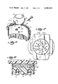
FIG. 5 is a top plan view of the bag body;
FIG. 6 is an enlarge-scale fragmentary perspective view showing the putter mounting clip;
FIG. 7 is a bottom plan view of the bag body;
FIG. 8 is an enlarged scale fragementary cross-sectional view taken on line 8--8 of FIG. 7.
DETAILED DESCRIPTION
The golf bag 10 includes a body 12 and a cover 14. These parts are preferably molded of the same kinds of semi-rigid, tough synthetic plastic material that is used in the manufacture of plastic airline luggage, portable TV cabinets, automobile body parts and the like, and using the same molding techniques.
The body 12 includes a perimetrical sidewall 16 of generally rounded-rectangular plan figure, a bottom wall 18 and a top wall 20. For convenience in description, the broader sides of the body are herein designated the front, 22, and the back 24. The two narrower sides are herein designated the handle end, 26, and the towel end, 28.
The top wall 20 is shown provided with a horseshoe-shaped outer portion 30, bordering the front and rear sides and the towel end, and with a raised center portion 32 bordering the handle end wall 26. This center portion 32 is stepped-up at 34 from the level of the outer portion 30 by approximately the amount that the shaft of the typical longest-shafted wood is longer than the shaft of the typical longest-shafted iron.
The upper, inner side of the bottom wall 18 is shown provided with a plurality of upwardly opening socket-like fixtures 36. The top wall 20 is shown provided with a corresponding plurality of similarly arranged openings 38. A respective tube 40 extends between each fixture 36 and each opening 38. In some instances the walls 18 and 20 and the tubes 40 would all be integrally molded together, perhaps even with some or all of the bag body, but in other instances these parts would be separately molded, then fabricated together e.g. by solvent welding, thermal bonding, adhesive bonding or the like. Fabrication of separately formed parts permits the tubes 40 to form as an extrusion that is cut to length. By preference the tubes 40, or at least those that are to receive club shafts, are longitudinally ribbed so as to be corrugated as seen in transverse cross-section, and radially resilient in order to frictionally resiliently hold the handgrips of the respective clubs received therein, as are the fixtures 36.
The space 42 within the body but outside the tubes 40 may be left empty or may be filled, e.g. with a foamed in situ mechanical shock-cushioning plastic polymer. In fact, the tubes 40 may be formed as an integral, non-foamed skin on such material.
The top wall 20 is shown provided with overlay means, in the form of one or more sculptured blocks 44 e.g. made of integrally-skinned semi-rigid foamed plastic resin or a hollow molded shell of plastic material similar to that used in the manufacture of the sidewall 16. Directly over and perimetrically in the vicinity of each opening 38 in the top wall 20, the block 44 is either missing, or provided with a matching opening 46 or provided with a slot or somewhat funnel-like or otherwise guiding surface 48, leading down to a matching opening 46. It is preferred that for each tube 40 that is to receive the handgrip and shaft of an iron or wood, that the respective guiding surface 48 constitute a cradle which is particularly shaped to permit the inverted top of the respective club head to nestle therein to a depth of, for instance, approximately one-quarter or so of the height of the respective club head.
Each cradle 48, regardless of its specific shape is designed not only to nestle a specific club head, but to accept the club head only when the respective club is guidingly homed thereinto or thereagainst so as to have a pre-selected angular orientation. As shown, it is preferred that the cradles 48 orient the clubs so that the woods, W1-W4, which are received in the single row of four cradles 48 which row runs parallel to the long sides of the top wall, down the center of the raised center portion 32, have their faces F at least generally parallel to one another with the heads of adjoining woods being rotated 180° relative to one another, e.g. so that the faces F of woods W1 and W2 confront one another, the backs B of the heads of woods W2 and W3 confront one another and the faces F of woods W3 and W4 confront one another. (By the designations W1, W2, etc., it is not meant to imply that these are necessarily a ONE wood, a TWO wood, etc., but only to differentiate the four woods a player is permitted to have in the bag during play governed by usual tournament rules. E.g. W1 might, in actual practice, be a FIVE wood, W2 might be a THREE wood, etc.)
Also by preference, the cradles 48 dispose the faces F in a set of at least generally parallel planes which lie at approximately 45° to the sides of the bag top wall.
Likewise by preference, five of the cradles 48 are provided at least approximately in a row on that leg of the outer portion 30 of the top wall 20 which lies between the raised center portion 32 and the back wall 24, this row extending at least generally parallel to those structures and having its five cradles 48 shaped to receive, in order, the five lowest-numbered irons, here designated I1-I5, with the longest-dimensioned axis of each club head oriented to project obliquely outwards, away from the adjoining row of woods, along planes parallel to those of the faces of the woods W1-W4. Further by preference, the remaining four of the cradles 48 are provided at least approximately in a row on the opposite leg of the outer portion 30 of the top wall 20, this row extending at least generally parallel to the other two and having its four cradles 48 shaped to receive, in order, the four highest-numbered irons, here designated I6-I9, with the longest-dimensioned axis of each club head oriented to project obliquely outwards, away from the adjoining woods W1-W4, along planes parallel to those of the faces of the woods. This preference clearly is not a slavish one; note that the cradle for the head of club I6 is oriented to point the club head more toward the handle end wall of the bag body (in order to avoid interference with another feature).
The preference for forming the block or blocks 44 separately, then adhering or otherwise securing it or them in place upon the wall 20 is to facilitate mass manufacture, it being thereby possible to make the same basic bag 10 in larger quantities, and to customize it to accept the club heads of each particular golfer by making the block(s) 44 to order, or in a range of different styles. Of course it would be possible, if desired, to form the cradles 48 directly in the top wall 20 and to eliminate the provision of the block or blocks 44. A middle way would be to mold-in cradles for the woods W1-W4, but provide a sculpture block or blocks for cradling the irons I1-I9. The deck of the bag 10 whether constituted by the top wall 20 or one or more sculpture blocks 44, or both, may include additional openings which provide the mouths for additional sockets, tubes, wells or the like. Three are illustrated, being openings 50, 52 and 54, respectively for removably receiving a conventional rake/ball retriever tool R, an umbrella U, and a putter P. Each respective tube 56 has an open upper end mounted to the deck perimetrically of the respective opening, and a lower end fixed to the bottom wall 18.
If desired, any or all of the tubes 40, 56 may be supported at a level above their lower ends, instead of or in addition to being supported at their lower ends, e.g. by passing through an apertured plate (not shown) mounted at an intermediate level in the bag body.
Any or all of the tubes 56 may be provided with interior grippers such as corrugations 58 for frictionally gripping the element R, U or P removably received therein.
The well 54/56 for the putter P is shown provided with an adjustable securement assembly 60 for releasably gripping the throat of the shaft of the putter P. In the preferred embodiment shown, the assembly 60 includes a bracket 62 adapted to be mounted to the bag sidewall 16 at the desired height e.g. by installing nut and bolt assemblies 64 through selectively aligned openings 66, 68 in the bracket 62 and bag sidewall 16 (and respective tube 56, if necessary). A universal joint ball 70 is based on the bracket 62. A universal joint socket 72 is mounted on the ball 70. A clip 74 is mounted on the socket 72 via a fixture 76 which, if tightened via the knurled collar 78 fixes the socket 72 to the ball 70, but which, if loosened, permits the socket 72 to be swiveled on the ball 70. Thus, in an initial adjustment to accommodate a particular putter P, the bracket 62 is placed at an acceptable height and is secured in place using the fasteners 64, then the socket 72 is swiveled on the ball 70 until the clip 74 is disposed at the proper place at the mouth of the well 54/56 to receive the throat of the putter P. Then the collar 78 is tightened to lock-in this position. Accordingly, the putter may be easily slid into the well 54/56 and its throat frictionally laterally urged into the clip 74 for dispositioning the putter head in view for ready access. Removal of the putter is accomplished by grasping its head, urging the throat laterally out of the clip and longitudinally withdrawing the putter upwards out of the well 54/56.
If desired, the well for the putter could be made more similar to the wells for the other club, with the adjustable securement assembly being replaced by a respective cradle similar to the cradles 48. Conversely, others of the wells could be provided with adjustable securement assemblies in lieu of cradles, if desired.
The cover 14 preferably is molded as an integral member of the same material as the body 12. It includes an end wall 80 and a perimetrical skirt 82. Toggle fasteners 84, such as are used to fasten the halves of luggage shells to one another are provided between the cover skirt 82 and the body sidewall 16 at a level near the top wall 20 where the cover, when in place, skirts the body sidewall. Accordingly, by preference, the cover 14 may be entirely removed by unfastening the toggle fasteners 84. When in place, the cover 14 completely encloses the deck and thus covers over all of the club heads and tools which are exposed on the deck. In order to further protect the clubs and tools in transit, the cover 14 preferably is provided with a liner 86 of resilient foamed plastic material, e.g. of the type conventionally used for cushioning camera equipment in the carrying cases of professional photographers.
By preference, the body 12 includes a base 88 in the form of a turntable 90 mounted to the bottom wall 18 via a turntable bearing assembly 92, which may be of a conventional type used in the manufacture of swivel furniture (bearing balls trapped between two ring-shaped races respectively fixed to the turntable and to the bag bottom wall. Accordingly, when the bag is upright and resting on the base 88, the user need not reach around the bag to gain access to a particular club, tool or accessory, but may instead manually rotate the bag on the base until the element the user wishes to gain access to is readily at hand. Means (not illustrated in detail) could be provided to lock the base against rotation for instances when it is desired that the bag not be rotatable relative to the base.
As shown, the bottom of the turntable plate is provided with a plurality of semi-recessed castors 94, preferably of the same ball-transfer type that is conventionally used to the bottoms of luggage (and for the same purpose: to facilitate baggage transfer along airport concourses and the like, by permitting the transferor to roll the bag along on its castors). When provided, the castors 94 are preferably equipped with removable caps 96 which, as shown, may be hinged to the bottom of the turntable at 98 and adapted to be received in recesses 100 when not in use. Thus, when it is desired to stabilize the bag against being able to roll, the caps 96 are readily folded about their hinges 98 and snapped in place covering the respective castors 94.
What remains to be described are various accessory features, preferably provided as shown in and about the sidewall 16 of the bag body 12.
The handle end wall 26 of the bag body is shown provided with a shoulder strap 102 and a hand grip 104. Either may be molded integrally with the bag body and either may be provided in any other well-known manner, e.g. of leather or of fabric webbing connected by D-rings to anchors provided on the wall 26. The presently preferred hand grip 104 is integrally molded so as to have anatomically conforming surfaces e.g. as illustrated at 106.
The towel end wall 28 of the bag body is shown provided generally in its upper half, with a vertically long, horizontally narrow recess 108. At the top of the recess 108, the wall 28 is provided with a mounting ring for a golfer's towel T and about two-thirds of the way down from the top of the recess 108, the wall 28 is provided, within the recess, with a loop-shaped retainer 110, through which the lower portion of the towel may be pulled when not in use. The loop 110 functions in much the way that a tieback for window drapes releasably keeps them back out of the way.
The front wall 22 of the sidewall 16 is shown provided with three accessory features that are discretely located in serially, axially spaced relation along the median of the front wall 22. From the top, these features include a bay-window-like compartment 112 with a horizontally slidable tambour door 114 on the front and a snap-open, snap-closed, hinged lid 116. The internal wall 118 of this compartment is shown in FIG. 3, from which it will be seen that the inner, approximately half of the volume of this compartment and its wall 118 take up a portion of the space within the bag body that lies outside the various tubes and wells for clubs and tools. Next below the compartment 112 is a vertically-oriented cylindrical compartment 120 sized and shaped to receive a Thermos jug J or the like. To this end, the internal wall 122 thereof includes a shelf 124 and the resulting well is closed by a complementarily semi-cylindrical snap-closed door 126. Near the bottom is a shoe storage compartment 128 having an internal wall 130 and a bin-type front member 132. The latter is pivotally mounted in the recess defined by the internal wall 130 to pivot about a horizontal axis near its lower edge, between a closed position wherein the front wall 134 is more nearly flush with the golf bag body front wall 22, and an open position, in which its upper end is particularly tilted out so that access may be gained to the shoe storage compartment that is defined between the inner face of the front wall 134 and the internal wall 130. The access door 132 may be provided with a friction fit for retaining it in the open and closed position in which it is placed, and/or it may be provided with securement means such as a snap fastener or the like (not shown in detail). The front member 132 may be removably mounted to the bag body so that when the front member 132 is tilted out it may be entirely removed in much the same way that a desk drawer can be conventionally removed from a desk by fully opening it, then performing an auxiliary maneuver, such as tilting to a different angle and pulling some more.
By preference, the front member includes means for removably securing thereto the golfer's shoes S which may be carried in the compartment 128. These means are shown including two opposed pairs of spring-urged plungers 136. The plungers pairs are arranged to each frictionally grip a shoe laterally between them by resiliently, opposingly engaging it e.g. between vamp and sole at about the narrowest part. The front member 132 further includes an internal ledge 138 on which the shoes S rest, toe-down, when received in the compartment 128.
The back wall 24 of the bag body sidewall 16 is shown including compartments 140 and 142 which may be respectively similar to the compartments 112 and 120, although possibly differently oriented, sized and/or proportioned.
The internal walls of all the compartments may be integrally molded with the bag body sidewall, or may be separately molded, and fabricated into appropriately corresponding openings molded or cut into the bag body sidewall. The various compartment doors may be integrally hinged to frames mounted to the sidewall perimetrically of the various compartment recesses, or may be otherwise hinged or mounted for opening, closing, and for securement in a closed condition. Where necessary or desired, locks may be provided against all access to the bag contents via compartment doors and cover.
It should now be apparent that the golf bag as described hereinabove, possesses each of the attributes set forth in the specification under the heading "Summary of the Invention" hereinbefore. Because it can be modified to some extent without departing from the principles thereof as they have been outlined and explained in this specification, the present invention should be understood as encompass-all such modifications as are within the spirit and scope of the following claims.

Claims (32)

What is claimed is:
1. A golf bag, comprising:
a body including a generally tubular perimetrical sidewall and a lower end wall providing an interior space;
means providing an upper deck for said body;
means providing a plurality of individual generally longitudinally oriented wells in said interior space, each opening through said deck and being adapted to axially slidingly removably receive an elongated item of golfing equipment such as a golf club shaft, handle end first;
means on said deck individually associated with each of at least several of said wells for removably accepting and holding a respective golf club head means;
each said well being constituted by a respective tube having opposite ends mounted and extending between said deck and said lower end wall;
at least one of said tubes including means extending throughout a portion of the length thereof constructed and arranged for resiliently gripping a corresponding portion of the respective golf club when such respective golf club is received handle end first into such tube;
said sidewall including at least one handle means whereby said golf bag may be hand-carried; and
cover means including a cover and securement means for releasably securing the cover to the sidewall in domed enclosing relation to said deck.
2. The golf bag of claim 1, wherein:
said body is made of molded semi-rigid material.
3. The golf bag of claim 2, wherein:
said cover is made of molded semi-rigid material.
4. The golf bag of claim 3, wherein:
said cover includes a liner of resilient cushioning material.
5. The golf bag of claim 1, wherein:
at least one of said accepting and holding means comprises an upwardly opening cradle formed in said deck where the respective said well opens through said deck, said cradle being asymetrically shaped angularly of such opening, in a sense such as to socketingly receive the top of a respective golf club head only when, as such golf club while being received handle-end first in the respective said well is guided to assume a unique angular orientation about the longitudinal axis of its shaft.
6. The golf bag of claim 5, wherein:
a respective said cradle is provided for each of nine said wells, which are shaped to receive the backs of a series of nine respective irons.
7. The golf bag of claim 6, wherein:
a further respective said cradle is provided for each of four said wells, which are shaped to receive the backs of a series of four respective woods.
8. The golf bag of claim 7, wherein:
said cradles are grouped in respective clusters, with the said cradles for the irons flanking a centrally located cluster of respective said cradles for the woods.
9. The golf bag of claim 8, wherein:
the deck is of split-level form, with an upper level for said cluster of cradles for the woods, and a lower level for said cradles for the irons.
10. The golf bag of claim 9, wherein:
said cradles are provided in three rows, consisting of a central row having said upper level and two flanking rows for said lower level.
11. The golf bag of claim 10, wherein:
the cradles for the woods are angularly oriented to face the woods in two groups of two facing woods with faces disposed approximately diagonally to a rectangular array defined by said three rows; and
the cradles for the irons are angularly oriented to face the irons at least generally parallel to the woods.
12. The golf bag of claim 5, wherein:
said body includes an upper end wall with said deck comprising a separately-formed sculptured block means mounted thereon, said wells opening through said upper end wall and each said cradle being formed in said sculptured block means.
13. The golf bag of claim 5, wherein:
at least another of said accepting and holding means comprises an adjustably-mounted clip mounted to said body and juxtaposed with where the respective well opens through said deck;
said clip being constructed and mounted to releasably grip a putter, in the putter head region, when such putter is inserted handle end first into the respective well.
14. The golf bag of claim 1, wherein:
said at least one tube is corrugated for resilient radial expansion throughout at least a portion of the length thereof for adapting that tube to resiliently grip a corresponding portion of the respective golf club when received handle end first into such tube.
15. The golf bag of claim 1, wherein:
the body further includes a base underlying said bag body lower end wall, said base comprising a turntable plate and turntable bearing means securing the turntable plate to the bag body for providing for rotation of the body but for the base as said golf bag rests on said base.
16. The golf bag of claim 15, wherein:
the turntable further includes a plurality of angularly distributed, rollable castors, so that the golf bag rests on said base for instance while being transported through an airport terminal, said golf bag may be rolled-along on said castors.
17. The golf bag of claim 16, wherein:
said castors are of the ball transfer type.
18. The golf bag of claim 16, further including:
cap means movably mounted on said turntable for removably covering the castors for temporarily isolating them from use.
19. The golf bag of claim 1, further including:
a vertically elongated external recess formed in said sidewall;
fastener means on said sidewall near the top of said recess, for securing a golfer's towel to said golf bag for storage in said recess.
20. The golf bag of claim 19, further including:
a keeper means for releasably keeping such golfer's towel stowed in said recess when such towel is not in use.
21. The golf bag of claim 19 wherein:
said sidewall is of generally rectangular figure in plan, so as to have two pairs of opposed walls, including a front wall, a rear wall, a handle end wall and a towel end wall;
said handle means being based on said handle end wall and said recess being provided on said towel end wall.
22. The golf bag of claim 1, wherein:
said body is made of molded, semi-rigid material and said sidewall incorporates a compartment which is partially recessed into said space and which includes an internal wall at least partially isolating such compartment from the remainder of said space; such compartment further including a movably mounted openable closure member.
23. The golf bag of claim 22, wherein:
the openable closure member is a hinged snap lid.
24. The golf bag of claim 22, wherein:
the openable closure member is a tambour door.
25. The golf bag of claim 22, wherein:
the openable closure member is a hinged cover door.
26. The golf bag of claim 22, wherein:
said openable closure is a pivoted bin front panel member having an interior face provided with means for removably mounting a pair of golfer's shoes thereto for storage within the respective compartment.
27. The golf bag of claim 26, further including:
a ledge on said bin front interior face for supporting such shoes when so mounted to said bin front panel member.
28. The golf bag of claim 26, wherein:
said means for removably mounting the golfer's shoes include opposed pairs of spring-loaded plungers mounted on said bin front panel member.
29. The golf bag of claim 22, wherein:
the compartment is sized and shaped to removably receive a pair of golfer's shoes.
30. The golf bag of claim 22, wherein:
the compartment is sized and shaped to removably receive a thermally insulated, generally cylindrically shaped food and beverage container.
31. The golf bag of claim 1, wherein:
one of said wells is constructed and arranged to removably, slidingly receive a golfer's umbrella.
32. The golf bag of claim 1, wherein:
one of said wells is constructed and arranged to removably, slidingly receive a golfer's ball retriever/rake tool.
US06/287,626 1981-07-28 1981-07-28 Golf bag Expired - Lifetime US4383563A (en)

Priority Applications (2)

Application Number Priority Date Filing Date Title
US06/287,626 US4383563A (en) 1981-07-28 1981-07-28 Golf bag
EP82106423A EP0071115A3 (en) 1981-07-28 1982-07-16 Golf bag

Applications Claiming Priority (1)

Application Number Priority Date Filing Date Title
US06/287,626 US4383563A (en) 1981-07-28 1981-07-28 Golf bag

Publications (1)

Publication Number Publication Date
US4383563A true US4383563A (en) 1983-05-17

Family

ID=23103710

Family Applications (1)

Application Number Title Priority Date Filing Date
US06/287,626 Expired - Lifetime US4383563A (en) 1981-07-28 1981-07-28 Golf bag

Country Status (2)

Country Link
US (1) US4383563A (en)
EP (1) EP0071115A3 (en)

Cited By (66)

* Cited by examiner, † Cited by third party
Publication number Priority date Publication date Assignee Title
US4629202A (en) * 1983-12-12 1986-12-16 Nelson Veryl H Combination golf cart and bag
US4685561A (en) * 1985-10-03 1987-08-11 Reimers Eric W Golf bag device
US4703851A (en) * 1986-11-28 1987-11-03 Robert Stewert Combination gold bag and insert
US4767001A (en) * 1986-06-09 1988-08-30 Kim Young S Golf bag
US4779725A (en) * 1987-03-03 1988-10-25 Tampa G Manufacturing Co. Stackable golf bag
US4796789A (en) * 1985-08-02 1989-01-10 Reginald Willcocks Dual-function golf bag
US4875579A (en) * 1988-07-27 1989-10-24 Tak Seung W Portable container assembly for containing golf accessories
US4881638A (en) * 1988-03-09 1989-11-21 Haidon Industrial Co., Ltd. Golf bag with divider and putter housing
US4905827A (en) * 1988-11-07 1990-03-06 Kim Young S Rigid golf bag with rigid hinged cover
USRE33203E (en) * 1985-10-03 1990-04-24 Golf bag device
US4924682A (en) * 1989-05-23 1990-05-15 Penner Douglas B Golf bag beverage cooler
US4955472A (en) * 1989-05-26 1990-09-11 Wataru Yamazoe Golf bag with a club securing device
US5050730A (en) * 1989-08-07 1991-09-24 Suberbielle James E Golf club storage and transport container
US5082218A (en) * 1989-02-13 1992-01-21 Hoffman Ronald W Container stand
US5094345A (en) * 1990-12-19 1992-03-10 Edward Yonnetti Golf club organizing device
US5105958A (en) * 1991-04-18 1992-04-21 Patton James E Golfer's water bottle
US5135107A (en) * 1991-12-09 1992-08-04 Ingraham Clifford R Golf bag with golf club separators
US5209280A (en) * 1991-11-12 1993-05-11 Gevas Peter D Protective hood for golf clubs
US5215194A (en) * 1991-07-30 1993-06-01 Blanford Linda A Golf bag for use with carts
US5244086A (en) * 1991-07-29 1993-09-14 Welch Gordon D Enclosed golf bag with rotary cap
US5279414A (en) * 1992-10-13 1994-01-18 Brasher J W Golf club bag with club compartments
US5301519A (en) * 1992-08-13 1994-04-12 Howorka David J Golf bag cooler
US5311987A (en) * 1992-02-29 1994-05-17 Shin Han S Golf bag with form organizer
US5450958A (en) * 1992-02-29 1995-09-19 Shin; Han S. Foam organizer bag
US5458240A (en) * 1992-12-30 1995-10-17 Rich; Philip R. Golf bag with individual club head support pockets
US5465840A (en) * 1993-04-07 1995-11-14 Joh; William K. Golf bag, and methods of constructing and utilizing same
US5579795A (en) * 1996-01-25 1996-12-03 Colbo, Jr.; Kenneth G. Golf cart sun shade and inclement weather protection device
WO1996041660A1 (en) * 1995-06-08 1996-12-27 Shimel Jerry W Beverage storage apparatus for use with a golf bag
US5590773A (en) * 1995-08-17 1997-01-07 Robinett; Gordon Golf wet towel container
US5624028A (en) * 1992-02-29 1997-04-29 Byung Shin Foam organizer
US5699906A (en) * 1996-02-26 1997-12-23 Lombardo; Carl Golf club carrier
US5704475A (en) * 1996-04-23 1998-01-06 Jack; William Inflatable golf club protector
US5810064A (en) * 1997-02-14 1998-09-22 Skb Corporation Golf club travel bag
US5816397A (en) * 1997-01-21 1998-10-06 Ogio International, Inc. Golf club carrying apparatus
US5842565A (en) * 1997-01-06 1998-12-01 Hagaman; Smith Mccartney Golf bag for orienting inclined golf clubs
US5842564A (en) * 1997-09-18 1998-12-01 Clement; Charles R. Holder for golf clubs
US5868247A (en) * 1997-01-31 1999-02-09 Schrader; Gunter Convertible hardshell golfbag
US5921387A (en) * 1997-04-14 1999-07-13 Arzoomanian; Mark Protective cover for a golf bag
US5950825A (en) * 1997-01-06 1999-09-14 Shin; Byung Golf bag for protecting golf club shafts
US5954199A (en) * 1997-01-30 1999-09-21 Stratton; Harry A. Golf bag with club separator
US5971409A (en) * 1998-02-09 1999-10-26 Butz; Byron N. Carrying case adapted for use with a golf pull cart
WO2000006260A1 (en) * 1998-07-25 2000-02-10 Saeho Chang Golf club securing and protection device for a golf bag
US6076668A (en) * 1998-12-31 2000-06-20 Keane; Vincent Golf head cover organizer
US6126050A (en) * 1998-02-27 2000-10-03 Aliano, Jr.; Joseph F. System for attaching a golf bag to a golf car
US6161692A (en) * 1999-01-05 2000-12-19 Lizarraga; Hector Multi-purpose golf bag
US6202840B1 (en) * 1998-07-25 2001-03-20 Saeho Chang Golf club securing and protection device for a golf bag
US6357585B1 (en) 1997-01-06 2002-03-19 Brian Byung Woo Shin Golf bag insert
US6367625B1 (en) 1999-08-26 2002-04-09 Gordon J. Zobel Protective cover for a golf bag
US6422444B1 (en) 2000-06-08 2002-07-23 John A. Richardson Golf bag with angled receptacles
US6508359B1 (en) * 1997-10-23 2003-01-21 Zhenzhen Zhiyou Industrial Co., Ltd. Golf bag
US6622859B2 (en) * 1999-10-26 2003-09-23 Morgenstern J{Overscore (Urgen Golf bag
US6641192B2 (en) 2000-08-25 2003-11-04 Charles R. Eschenfelder Storage cabinet for use in a golf cart
US20040016661A1 (en) * 2000-10-27 2004-01-29 Puskaric Joseph Anthony Golf club organizer
US20050155882A1 (en) * 2004-01-15 2005-07-21 Pratt Michael J. Pocket closure device
US20050199519A1 (en) * 2004-03-09 2005-09-15 Kim Young S. Golf club travel bag
GB2424590A (en) * 2005-04-01 2006-10-04 Andrew Johnson A wheeled golf bag
US20060249552A1 (en) * 2005-05-09 2006-11-09 I-Concept International Limited Ergonomic golf bag handle
US20080011631A1 (en) * 2006-07-14 2008-01-17 James Kim Golf bag with club head locking mechanism
US20080217193A1 (en) * 2007-03-09 2008-09-11 Jatin Amin Golf bag
US7481311B1 (en) * 2006-03-09 2009-01-27 Old James A Gold club bag for use with golf cart
US20150014196A1 (en) * 2013-07-13 2015-01-15 Novis Gene Hargis Golf bag divider accessory and method of making same
US20150027833A1 (en) * 2009-11-30 2015-01-29 Thule Organization Solutions, Inc. Backpack with integrated rigid storage container
US9433838B2 (en) 2014-10-08 2016-09-06 Stout Products, Llc Shoe holder arranged for attachment to a golf bag
US20170021668A1 (en) * 2015-07-21 2017-01-26 Xiaomi Inc. Universal wheel assembly and suitcase
US20180243624A1 (en) * 2015-08-17 2018-08-30 Eamonn O'KEEFE Golf bag
US11077345B2 (en) * 2015-03-02 2021-08-03 Karsten Manufacturing Corporation Sub-assembly for a golf bag and a golf bag system for recipient self-assembly

Families Citing this family (4)

* Cited by examiner, † Cited by third party
Publication number Priority date Publication date Assignee Title
WO1991010482A1 (en) * 1990-01-12 1991-07-25 Allan Macleay Cumming Golf case/buggy
WO1992016266A1 (en) * 1991-03-15 1992-10-01 Ross Leslie Phelps Golf bag
JP2843674B2 (en) * 1992-02-19 1999-01-06 シェリング・コーポレーション Cloning and expression of a humanized monoclonal antibody against human interleukin-4
AU691464B3 (en) * 1997-11-28 1998-05-14 Gordon, Scott A. Apparatus for supporting golf clubs

Citations (11)

* Cited by examiner, † Cited by third party
Publication number Priority date Publication date Assignee Title
US2596578A (en) * 1949-03-05 1952-05-13 Grace H Mcintyre Wheeled suitcase
US2605989A (en) * 1949-01-05 1952-08-05 Oshkosh Trunks And Luggage Turntable base for trunks
US2783054A (en) * 1953-11-27 1957-02-26 Carr Ind Foldable wheeled golf club carrier
US2879819A (en) * 1956-04-26 1959-03-31 John S Turnbull Golf club protecting and separating devices
US3373911A (en) * 1966-11-25 1968-03-19 Melvin J. Kebelbeck Golf cart mounted shoe pack
US3941398A (en) * 1974-08-05 1976-03-02 Nelson Karl M Golf club holder
US3985171A (en) * 1975-09-02 1976-10-12 Nbs, Inc. Club protecting cover for golf bag
US4012051A (en) * 1975-12-23 1977-03-15 Embinder Donald N Golf club carrier
US4100652A (en) * 1977-01-28 1978-07-18 The Raymond Lee Organization, Inc. Golf club anchor
US4142563A (en) * 1976-11-03 1979-03-06 Sikob Svensk Industris Konstruktions-Och Berakningskontor Ab Golf bag
US4319616A (en) * 1980-08-04 1982-03-16 Light Richard D Golf club carrier

Family Cites Families (3)

* Cited by examiner, † Cited by third party
Publication number Priority date Publication date Assignee Title
US3172681A (en) * 1963-03-13 1965-03-09 Moses Charles Golf club carrier
US3460597A (en) * 1966-10-26 1969-08-12 Noel Daly Golf bags
GB2068741B (en) * 1980-01-07 1983-06-08 Isabel J R Golf club bags

Patent Citations (11)

* Cited by examiner, † Cited by third party
Publication number Priority date Publication date Assignee Title
US2605989A (en) * 1949-01-05 1952-08-05 Oshkosh Trunks And Luggage Turntable base for trunks
US2596578A (en) * 1949-03-05 1952-05-13 Grace H Mcintyre Wheeled suitcase
US2783054A (en) * 1953-11-27 1957-02-26 Carr Ind Foldable wheeled golf club carrier
US2879819A (en) * 1956-04-26 1959-03-31 John S Turnbull Golf club protecting and separating devices
US3373911A (en) * 1966-11-25 1968-03-19 Melvin J. Kebelbeck Golf cart mounted shoe pack
US3941398A (en) * 1974-08-05 1976-03-02 Nelson Karl M Golf club holder
US3985171A (en) * 1975-09-02 1976-10-12 Nbs, Inc. Club protecting cover for golf bag
US4012051A (en) * 1975-12-23 1977-03-15 Embinder Donald N Golf club carrier
US4142563A (en) * 1976-11-03 1979-03-06 Sikob Svensk Industris Konstruktions-Och Berakningskontor Ab Golf bag
US4100652A (en) * 1977-01-28 1978-07-18 The Raymond Lee Organization, Inc. Golf club anchor
US4319616A (en) * 1980-08-04 1982-03-16 Light Richard D Golf club carrier

Cited By (79)

* Cited by examiner, † Cited by third party
Publication number Priority date Publication date Assignee Title
US4629202A (en) * 1983-12-12 1986-12-16 Nelson Veryl H Combination golf cart and bag
US4796789A (en) * 1985-08-02 1989-01-10 Reginald Willcocks Dual-function golf bag
USRE33203E (en) * 1985-10-03 1990-04-24 Golf bag device
US4685561A (en) * 1985-10-03 1987-08-11 Reimers Eric W Golf bag device
US4767001A (en) * 1986-06-09 1988-08-30 Kim Young S Golf bag
US4703851A (en) * 1986-11-28 1987-11-03 Robert Stewert Combination gold bag and insert
US4779725A (en) * 1987-03-03 1988-10-25 Tampa G Manufacturing Co. Stackable golf bag
US4881638A (en) * 1988-03-09 1989-11-21 Haidon Industrial Co., Ltd. Golf bag with divider and putter housing
US4875579A (en) * 1988-07-27 1989-10-24 Tak Seung W Portable container assembly for containing golf accessories
US4905827A (en) * 1988-11-07 1990-03-06 Kim Young S Rigid golf bag with rigid hinged cover
US5082218A (en) * 1989-02-13 1992-01-21 Hoffman Ronald W Container stand
US4924682A (en) * 1989-05-23 1990-05-15 Penner Douglas B Golf bag beverage cooler
US4955472A (en) * 1989-05-26 1990-09-11 Wataru Yamazoe Golf bag with a club securing device
US5050730A (en) * 1989-08-07 1991-09-24 Suberbielle James E Golf club storage and transport container
US5094345A (en) * 1990-12-19 1992-03-10 Edward Yonnetti Golf club organizing device
US5105958A (en) * 1991-04-18 1992-04-21 Patton James E Golfer's water bottle
US5244086A (en) * 1991-07-29 1993-09-14 Welch Gordon D Enclosed golf bag with rotary cap
US5215194A (en) * 1991-07-30 1993-06-01 Blanford Linda A Golf bag for use with carts
US5209280A (en) * 1991-11-12 1993-05-11 Gevas Peter D Protective hood for golf clubs
US5135107A (en) * 1991-12-09 1992-08-04 Ingraham Clifford R Golf bag with golf club separators
US5624028A (en) * 1992-02-29 1997-04-29 Byung Shin Foam organizer
US5311987A (en) * 1992-02-29 1994-05-17 Shin Han S Golf bag with form organizer
US5450958A (en) * 1992-02-29 1995-09-19 Shin; Han S. Foam organizer bag
US5301519A (en) * 1992-08-13 1994-04-12 Howorka David J Golf bag cooler
US5279414A (en) * 1992-10-13 1994-01-18 Brasher J W Golf club bag with club compartments
US5458240A (en) * 1992-12-30 1995-10-17 Rich; Philip R. Golf bag with individual club head support pockets
US5465840A (en) * 1993-04-07 1995-11-14 Joh; William K. Golf bag, and methods of constructing and utilizing same
WO1996041660A1 (en) * 1995-06-08 1996-12-27 Shimel Jerry W Beverage storage apparatus for use with a golf bag
US5769219A (en) * 1995-06-08 1998-06-23 Shimel; Jerry W. Beverage storage apparatus for use with a golf bag
US5590773A (en) * 1995-08-17 1997-01-07 Robinett; Gordon Golf wet towel container
US5579795A (en) * 1996-01-25 1996-12-03 Colbo, Jr.; Kenneth G. Golf cart sun shade and inclement weather protection device
US5699906A (en) * 1996-02-26 1997-12-23 Lombardo; Carl Golf club carrier
US5911322A (en) * 1996-02-26 1999-06-15 Lombardo; Carl Golf club carrier
US5704475A (en) * 1996-04-23 1998-01-06 Jack; William Inflatable golf club protector
US5950825A (en) * 1997-01-06 1999-09-14 Shin; Byung Golf bag for protecting golf club shafts
US6357585B1 (en) 1997-01-06 2002-03-19 Brian Byung Woo Shin Golf bag insert
US5842565A (en) * 1997-01-06 1998-12-01 Hagaman; Smith Mccartney Golf bag for orienting inclined golf clubs
US5816397A (en) * 1997-01-21 1998-10-06 Ogio International, Inc. Golf club carrying apparatus
US5954199A (en) * 1997-01-30 1999-09-21 Stratton; Harry A. Golf bag with club separator
US5868247A (en) * 1997-01-31 1999-02-09 Schrader; Gunter Convertible hardshell golfbag
US5810064A (en) * 1997-02-14 1998-09-22 Skb Corporation Golf club travel bag
US5927361A (en) * 1997-02-14 1999-07-27 Skb Corporation Golf club travel bag
US5921387A (en) * 1997-04-14 1999-07-13 Arzoomanian; Mark Protective cover for a golf bag
US5842564A (en) * 1997-09-18 1998-12-01 Clement; Charles R. Holder for golf clubs
US6508359B1 (en) * 1997-10-23 2003-01-21 Zhenzhen Zhiyou Industrial Co., Ltd. Golf bag
US5971409A (en) * 1998-02-09 1999-10-26 Butz; Byron N. Carrying case adapted for use with a golf pull cart
US6126050A (en) * 1998-02-27 2000-10-03 Aliano, Jr.; Joseph F. System for attaching a golf bag to a golf car
US6202840B1 (en) * 1998-07-25 2001-03-20 Saeho Chang Golf club securing and protection device for a golf bag
US6269947B1 (en) * 1998-07-25 2001-08-07 Saeho Chang Golf bag having multiple decks for isolating clubs
WO2000006260A1 (en) * 1998-07-25 2000-02-10 Saeho Chang Golf club securing and protection device for a golf bag
US6076668A (en) * 1998-12-31 2000-06-20 Keane; Vincent Golf head cover organizer
US6161692A (en) * 1999-01-05 2000-12-19 Lizarraga; Hector Multi-purpose golf bag
US6367625B1 (en) 1999-08-26 2002-04-09 Gordon J. Zobel Protective cover for a golf bag
US6622859B2 (en) * 1999-10-26 2003-09-23 Morgenstern J{Overscore (Urgen Golf bag
US6422444B1 (en) 2000-06-08 2002-07-23 John A. Richardson Golf bag with angled receptacles
US6641192B2 (en) 2000-08-25 2003-11-04 Charles R. Eschenfelder Storage cabinet for use in a golf cart
US7021459B2 (en) * 2000-10-27 2006-04-04 Joseph Anthony Puskaric Golf club organizer
US20040016661A1 (en) * 2000-10-27 2004-01-29 Puskaric Joseph Anthony Golf club organizer
US7628188B2 (en) 2004-01-15 2009-12-08 Ogio International, Inc. Pocket closure device
US7111731B2 (en) * 2004-01-15 2006-09-26 Ogio International, Inc. Pocket closure device
US20050155882A1 (en) * 2004-01-15 2005-07-21 Pratt Michael J. Pocket closure device
US7222733B2 (en) 2004-03-09 2007-05-29 Kim Young S Golf club travel bag
US20050199519A1 (en) * 2004-03-09 2005-09-15 Kim Young S. Golf club travel bag
GB2424590A (en) * 2005-04-01 2006-10-04 Andrew Johnson A wheeled golf bag
US7686163B2 (en) * 2005-05-09 2010-03-30 Jimmy Cheuk Tsang Ergonomic golf bag handle
US20060249552A1 (en) * 2005-05-09 2006-11-09 I-Concept International Limited Ergonomic golf bag handle
US7481311B1 (en) * 2006-03-09 2009-01-27 Old James A Gold club bag for use with golf cart
US20080011631A1 (en) * 2006-07-14 2008-01-17 James Kim Golf bag with club head locking mechanism
US7832557B2 (en) 2007-03-09 2010-11-16 Jatin Amin Golf bag
US20080217193A1 (en) * 2007-03-09 2008-09-11 Jatin Amin Golf bag
US20150027833A1 (en) * 2009-11-30 2015-01-29 Thule Organization Solutions, Inc. Backpack with integrated rigid storage container
US9392855B2 (en) * 2009-11-30 2016-07-19 Thule Organization Solutions, Inc. Backpack with integrated rigid storage container
US20150014196A1 (en) * 2013-07-13 2015-01-15 Novis Gene Hargis Golf bag divider accessory and method of making same
US9433838B2 (en) 2014-10-08 2016-09-06 Stout Products, Llc Shoe holder arranged for attachment to a golf bag
US11077345B2 (en) * 2015-03-02 2021-08-03 Karsten Manufacturing Corporation Sub-assembly for a golf bag and a golf bag system for recipient self-assembly
US20170021668A1 (en) * 2015-07-21 2017-01-26 Xiaomi Inc. Universal wheel assembly and suitcase
US10137732B2 (en) * 2015-07-21 2018-11-27 Xiaomi Inc. Universal wheel assembly and suitcase
US20180243624A1 (en) * 2015-08-17 2018-08-30 Eamonn O'KEEFE Golf bag
US10610750B2 (en) * 2015-08-17 2020-04-07 Eamonn O'KEEFE Golf bag rollers and accessories

Also Published As

Publication number Publication date
EP0071115A2 (en) 1983-02-09
EP0071115A3 (en) 1983-10-12

Similar Documents

Publication Publication Date Title
US4383563A (en) Golf bag
US4522299A (en) Rigid polyethylene carry golf bag with stand
US4852896A (en) Golf equipment carrier with rotating club reducing frame
US5599037A (en) Golf bag holder
US3941398A (en) Golf club holder
US5112068A (en) Convertible golf cart and bag
US4319616A (en) Golf club carrier
US6394325B1 (en) Golf cart cooler
US7832557B2 (en) Golf bag
US2551780A (en) Stand-up golf bag
US4793532A (en) Carrier for ball game items
US5988379A (en) Golf bag with divided ball pouch, sliding shelves, and cart strap securing system
US7481311B1 (en) Gold club bag for use with golf cart
US6217042B1 (en) Golf club travel case
US6161692A (en) Multi-purpose golf bag
US20060022418A1 (en) Golf bag having integrated wheels and an extendable handle
US5879022A (en) Convertible golf cart and bag device and method of converting same
US20080217194A1 (en) Golf bag
US5234114A (en) Golfing equipment carrier
US20070215500A1 (en) Lightweight golf bag
US5975170A (en) Golf bag cover device and method of installation
US7419037B2 (en) Equipment carrier with a rotatable handle
US3953045A (en) Ferrett bag and cart
US20050072695A1 (en) Golf club bag
US4143694A (en) Golf bag container

Legal Events

Date Code Title Description
STCF Information on status: patent grant

Free format text: PATENTED CASE

MAFP Maintenance fee payment

Free format text: PAYMENT OF MAINTENANCE FEE, 4TH YEAR, PL 96-517 (ORIGINAL EVENT CODE: M170); ENTITY STATUS OF PATENT OWNER: SMALL ENTITY

Year of fee payment: 4

MAFP Maintenance fee payment

Free format text: PAYMENT OF MAINTENANCE FEE, 8TH YEAR, PL 96-517 (ORIGINAL EVENT CODE: M171); ENTITY STATUS OF PATENT OWNER: SMALL ENTITY

Year of fee payment: 8

FEPP Fee payment procedure

Free format text: PAYOR NUMBER ASSIGNED (ORIGINAL EVENT CODE: ASPN); ENTITY STATUS OF PATENT OWNER: SMALL ENTITY

MAFP Maintenance fee payment

Free format text: PAYMENT OF MAINTENANCE FEE, 12TH YR, SMALL ENTITY (ORIGINAL EVENT CODE: M285); ENTITY STATUS OF PATENT OWNER: SMALL ENTITY

Year of fee payment: 12