US4381997A - Differential pressure valve for a fuel injection system - Google Patents
Differential pressure valve for a fuel injection system Download PDFInfo
- Publication number
- US4381997A US4381997A US06/320,374 US32037481A US4381997A US 4381997 A US4381997 A US 4381997A US 32037481 A US32037481 A US 32037481A US 4381997 A US4381997 A US 4381997A
- Authority
- US
- United States
- Prior art keywords
- filter element
- valve
- spring
- chamber
- differential pressure
- Prior art date
- Legal status (The legal status is an assumption and is not a legal conclusion. Google has not performed a legal analysis and makes no representation as to the accuracy of the status listed.)
- Expired - Fee Related
Links
- 239000000446 fuel Substances 0.000 title abstract description 21
- 238000002347 injection Methods 0.000 title abstract description 9
- 239000007924 injection Substances 0.000 title abstract description 9
- 210000003141 lower extremity Anatomy 0.000 claims 3
- 210000001364 upper extremity Anatomy 0.000 claims 2
- 238000007789 sealing Methods 0.000 abstract description 11
- 238000002485 combustion reaction Methods 0.000 abstract description 2
- 239000002245 particle Substances 0.000 description 7
- 238000001914 filtration Methods 0.000 description 3
- 230000001419 dependent effect Effects 0.000 description 2
- 239000004033 plastic Substances 0.000 description 2
- 230000007797 corrosion Effects 0.000 description 1
- 238000005260 corrosion Methods 0.000 description 1
- 230000000694 effects Effects 0.000 description 1
- 239000012530 fluid Substances 0.000 description 1
- 230000007257 malfunction Effects 0.000 description 1
- 239000000463 material Substances 0.000 description 1
- -1 shavings Substances 0.000 description 1
- 238000011144 upstream manufacturing Methods 0.000 description 1
Images

Classifications
-
- F—MECHANICAL ENGINEERING; LIGHTING; HEATING; WEAPONS; BLASTING
- F02—COMBUSTION ENGINES; HOT-GAS OR COMBUSTION-PRODUCT ENGINE PLANTS
- F02M—SUPPLYING COMBUSTION ENGINES IN GENERAL WITH COMBUSTIBLE MIXTURES OR CONSTITUENTS THEREOF
- F02M69/00—Low-pressure fuel-injection apparatus ; Apparatus with both continuous and intermittent injection; Apparatus injecting different types of fuel
- F02M69/46—Details, component parts or accessories not provided for in, or of interest apart from, the apparatus covered by groups F02M69/02 - F02M69/44
- F02M69/52—Arrangement of fuel metering devices
-
- Y—GENERAL TAGGING OF NEW TECHNOLOGICAL DEVELOPMENTS; GENERAL TAGGING OF CROSS-SECTIONAL TECHNOLOGIES SPANNING OVER SEVERAL SECTIONS OF THE IPC; TECHNICAL SUBJECTS COVERED BY FORMER USPC CROSS-REFERENCE ART COLLECTIONS [XRACs] AND DIGESTS
- Y10—TECHNICAL SUBJECTS COVERED BY FORMER USPC
- Y10T—TECHNICAL SUBJECTS COVERED BY FORMER US CLASSIFICATION
- Y10T137/00—Fluid handling
- Y10T137/7722—Line condition change responsive valves
- Y10T137/7781—With separate connected fluid reactor surface
- Y10T137/7835—Valve seating in direction of flow
- Y10T137/7836—Flexible diaphragm or bellows reactor
-
- Y—GENERAL TAGGING OF NEW TECHNOLOGICAL DEVELOPMENTS; GENERAL TAGGING OF CROSS-SECTIONAL TECHNOLOGIES SPANNING OVER SEVERAL SECTIONS OF THE IPC; TECHNICAL SUBJECTS COVERED BY FORMER USPC CROSS-REFERENCE ART COLLECTIONS [XRACs] AND DIGESTS
- Y10—TECHNICAL SUBJECTS COVERED BY FORMER USPC
- Y10T—TECHNICAL SUBJECTS COVERED BY FORMER US CLASSIFICATION
- Y10T137/00—Fluid handling
- Y10T137/794—With means for separating solid material from the fluid
- Y10T137/8085—Hollow strainer, fluid inlet and outlet perpendicular to each other
Definitions
- the invention relates to a differential pressure valve for a fuel injection system.
- a differential pressure valve is already known in which the filter element is disposed in such a manner that an adjustment of the spring plate on the valve seat carrier for the purpose of changing the tension of the valve spring is not possible.
- the differential pressure valve in accordance with the invention for a fuel injection system has the advantage over the prior art in that despite the disposition of a filter element between the fuel supply line and the valve opening, the spring plate supported on the valve seat carrier is displaceable, and the spring force of the valve spring thus can be changed. As a result it is assured that even with a differential pressure valve which is adjustable in this manner, the entry of small dirt particles into the gap between the diaphragm and the valve opening is avoided, thereby preventing a resultant malfunction on the part of the differential pressure valve.
- FIG. 1 shows a schematic cross-sectional view of a first exemplary embodiment of a differential pressure valve
- FIG. 2 shows a detailed elevational and cross-sectional view of a filter element as it is used in the exemplary embodiment of FIG. 1;
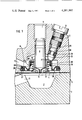
- FIG. 3 shows a further schematic cross-sectional view of a second exemplary embodiment of a differential pressure valve.
- the differential pressure valve 1 shown in FIG. 1 is, by way of example, part of a fuel metering and distribution valve in a fuel injection system in accordance with German Offenlegungsschrift No. 26 48 956 for a mixture-compressing internal combustion engine with externally supplied ignition, and more particularly, an engine adapted for continuous injection.
- a diaphragm 4 is tensioned between an upper housing 2 and a lower housing 3, and therefore arranged to separate a chamber 6 provided in the upper housing 2 from a chamber 7 provided in the lower housing 3 and thus arranged to act as the movable valve element of the differential pressure valve 1.
- a valve seat carrier 8 protrudes into the chamber 6 of the differential pressure valve 1 and has a valve opening 9 on its terminal end which is oriented toward the diaphragm 4.
- fuel can proceed out of the chamber 6, when the diaphragm 4 is deflected away from the valve seat carrier 8, into a fuel injection line 11 and from there to fuel injection valves, which are not shown.
- the chamber 6 of the differential pressure valve 1 communicates with a fuel supply line 12 downstream of a fuel metering valve (not shown).
- Fuel also flows into the chamber 7 in the lower housing 3 via a line 13, the pressure of which is constant or else is variable in a known (but not illustrated) manner in accordance with operating parameters of the engine.
- a spring loaded plate 15 supported displaceably on the valve seat carrier 8 is disposed in the chamber 6 coaxially with the valve seat carrier 8.
- Supported on the spring loaded plate 15 is a valve spring element 16 which is coaxial with the valve seat carrier 8 and the lower portion of this spring is adapted to engage a plate 17, which is supported on the diaphragm 4.
- the threaded bore 20 can be closed off from the outside by means of a sealed locking screw 21.
- a pin rigidly guided in a bore could act as the adjustment means for the spring loaded plate 15.
- a sealing ring 23 can be disposed in a groove 22 of the adjusting screw 18, which prevents the flow of fuel from the chamber 6 past the adjusting screw 18 and to the outside.
- the spring force of the valve spring 16 determines the fuel pressure differential between the chambers 6 and 7 at which the diaphragm 4 lifts from the valve seat carrier 8 and the valve opening 9 opens in order to permit fuel flow from chamber 6 through opening 9 in valve seat carrier 8 into a fuel injection line 11.
- a filter element 25 is disposed in the chamber 6 between the fuel supply line 12 and the valve opening 9 and arranged to have one end 26 engage the spring plate 15, for example, and with its other end 27 being supported in a sealing manner in a groove 28 provided in the wall of the chamber 6.
- the ends 26 and 27 of the filter element 25 may be made of plastic or of a suitable rubber product.
- a spring ring 29 is also disposed in the groove 28 in such a manner that it presses the end 27 of the filter element 25 in the axial direction of the valve against the wall of the groove 28 and thus assures not only holding, but also sealing.
- a disc 30 Connected with the upper end 26 of the filter element 25 is a disc 30, which is arranged to rest against the lower surface of the spring loaded plate 15 and is held in the position shown in FIG. 1 by means of the spring 16 that is disposed between plates 17 and 15, respectively.
- the filter element 25 has at least one filter area 33 between the ends 26 and 27 which is made up of one or more layers of filtering screen and/or some other suitable filtering material.
- the filter element 25 furthermore has at least one elastically deformable area 35, which in the illustrated exemplary embodiment begins immediately adjacent to the filter area 33 and extends in an undulatory fashion toward the end 27.
- the elastically deformable area 35 may be embodied in the form of a flexible walled diaphragm and to thereby permit an axial movement of the ends 26 and 27 toward or away from one another, without restricting the filtering effect of the filter element 25.
- the filter element 25 could also engage the spring loaded plate 17 with its end 26; however, then the end 27 would have to be supported, in the direction toward the spring plate 15, in a sealing manner above the fuel supply line 12 on the wall of the chamber 6.
- one end 38 of a filter element 37 is preferably associated with the spring loaded plate 17 in a sealing manner and the filter element 33 extends in an axial direction up to the other plate 15 as shown.
- the upper portion of the filter element is provided with an annulus 39 of plastic or rubber, as explained earlier herein, with the inner wall of the annulus so designed as to offer any resistance to fluid flow between the inner wall 40 and the confronting dependent wall of spring loaded plate 15.
Landscapes
- Engineering & Computer Science (AREA)
- Chemical & Material Sciences (AREA)
- Combustion & Propulsion (AREA)
- Mechanical Engineering (AREA)
- General Engineering & Computer Science (AREA)
- Fuel-Injection Apparatus (AREA)
- Safety Valves (AREA)
Abstract
A differential pressure valve is proposed for a fuel injection system of an internal combustion engine. The differential pressure valve includes a diaphragm embodied as the movable valve element, which separates two chambers from one another. A fuel supply line discharges into one chamber and a valve seat carrier provided with a valve opening protrudes into this chamber. This chamber also houses a filter element and a valve spring is disposed coaxially with the valve seat carrier between upper and lower spring plates. The filter element is disposed such that a subsequent change in the tension of the valve spring is also possible. To this end, the filter element can engage the upper spring plate on one side in a sealing manner and on the other side can be supported in a sealing manner in a groove of the wall of the chamber (FIG. 1). In order to assure the free mobility of the filter element, it is provided with an elastically deformable area. As shown in FIG. 2, the filter element may, however, also engage the lower spring plate in a sealing manner and with its other end surroundingly engage the spring plate with as little play as possible, to thereby form a labyrinth seal.
Description
This is a division, of application Ser. No. 123,534, filed Feb. 22, 1980.
The invention relates to a differential pressure valve for a fuel injection system. A differential pressure valve is already known in which the filter element is disposed in such a manner that an adjustment of the spring plate on the valve seat carrier for the purpose of changing the tension of the valve spring is not possible.
The differential pressure valve in accordance with the invention for a fuel injection system has the advantage over the prior art in that despite the disposition of a filter element between the fuel supply line and the valve opening, the spring plate supported on the valve seat carrier is displaceable, and the spring force of the valve spring thus can be changed. As a result it is assured that even with a differential pressure valve which is adjustable in this manner, the entry of small dirt particles into the gap between the diaphragm and the valve opening is avoided, thereby preventing a resultant malfunction on the part of the differential pressure valve.
As a result of the characteristics disclosed in the dependent claims, advantageous further embodiments of and improvements to the differential pressure valve disclosed are possible. It is particularly advantageous to support the end of the filter element remote from the end which engages the spring plate on the wall of the chamber of the differential pressure valve in such a manner as to provide a seal, and to further adapt the filter element to include at least one elastically deformable area, for instance, in the form of a folding diaphragm, which rolls down when movement occurs.
It is also advantageous to secure one end of the filter element in a sealing manner on the spring plate contacting the diaphragm and to have the other end of the filter element surroundingly engage the spring plate supported on the valve seat carrier with as little play as possible, the play acting as a labyrinth sealing means. As a result, free mobility of the spring plate supported on the valve seat carrier is assured.
The invention will be better understood and further objects and advantages thereof will become more apparent from the ensuing detailed description of preferred embodiments taken in conjunction with the drawings.
FIG. 1 shows a schematic cross-sectional view of a first exemplary embodiment of a differential pressure valve;
FIG. 2 shows a detailed elevational and cross-sectional view of a filter element as it is used in the exemplary embodiment of FIG. 1; and
FIG. 3 shows a further schematic cross-sectional view of a second exemplary embodiment of a differential pressure valve.
Turning now to the drawings, the differential pressure valve 1 shown in FIG. 1 is, by way of example, part of a fuel metering and distribution valve in a fuel injection system in accordance with German Offenlegungsschrift No. 26 48 956 for a mixture-compressing internal combustion engine with externally supplied ignition, and more particularly, an engine adapted for continuous injection. A diaphragm 4 is tensioned between an upper housing 2 and a lower housing 3, and therefore arranged to separate a chamber 6 provided in the upper housing 2 from a chamber 7 provided in the lower housing 3 and thus arranged to act as the movable valve element of the differential pressure valve 1. A valve seat carrier 8 protrudes into the chamber 6 of the differential pressure valve 1 and has a valve opening 9 on its terminal end which is oriented toward the diaphragm 4. Thus, fuel can proceed out of the chamber 6, when the diaphragm 4 is deflected away from the valve seat carrier 8, into a fuel injection line 11 and from there to fuel injection valves, which are not shown. The chamber 6 of the differential pressure valve 1 communicates with a fuel supply line 12 downstream of a fuel metering valve (not shown).
Fuel also flows into the chamber 7 in the lower housing 3 via a line 13, the pressure of which is constant or else is variable in a known (but not illustrated) manner in accordance with operating parameters of the engine.
A spring loaded plate 15 supported displaceably on the valve seat carrier 8 is disposed in the chamber 6 coaxially with the valve seat carrier 8. Supported on the spring loaded plate 15 is a valve spring element 16 which is coaxial with the valve seat carrier 8 and the lower portion of this spring is adapted to engage a plate 17, which is supported on the diaphragm 4. The spring loaded plate 15, with its conically shaped end remote from the valve spring 16, contacts an adjusting screw 18, which is rotatably supported in a threaded bore 20 provided in the upper housing 2. The threaded bore 20 can be closed off from the outside by means of a sealed locking screw 21. It may be particularly efficient from the standpoint of space for the threaded bore 20 and thus the adjusting screw 18 as well to be tilted relative to the axis of the valve seat carrier. In place of the adjusting screw 18, a pin rigidly guided in a bore could act as the adjustment means for the spring loaded plate 15. For the purpose of sealing and securing the adjusting screw 18 against twisting, a sealing ring 23 can be disposed in a groove 22 of the adjusting screw 18, which prevents the flow of fuel from the chamber 6 past the adjusting screw 18 and to the outside. By means of rotating the adjusting screw 18, the axial position of the spring loaded plate 15 with respect to the valve seat carrier 8 and thus the tension of the valve spring 16 can be varied. The spring force of the valve spring 16 determines the fuel pressure differential between the chambers 6 and 7 at which the diaphragm 4 lifts from the valve seat carrier 8 and the valve opening 9 opens in order to permit fuel flow from chamber 6 through opening 9 in valve seat carrier 8 into a fuel injection line 11.
There is now the danger that upstream of the chamber 6 of the differential pressure valve 1, dirt particles such as shavings, products of corrosion, particles from galvanized surfaces and the like may work loose and become caught in the narrow gap between the diaphragm 4 and the valve seat carrier 8, so that the proper functioning of the differential pressure valve 1 is interrupted or entirely prevented. In order to prevent such particles from reaching the valve opening 9, a filter element 25 is disposed in the chamber 6 between the fuel supply line 12 and the valve opening 9 and arranged to have one end 26 engage the spring plate 15, for example, and with its other end 27 being supported in a sealing manner in a groove 28 provided in the wall of the chamber 6. The ends 26 and 27 of the filter element 25 may be made of plastic or of a suitable rubber product. A spring ring 29 is also disposed in the groove 28 in such a manner that it presses the end 27 of the filter element 25 in the axial direction of the valve against the wall of the groove 28 and thus assures not only holding, but also sealing. Connected with the upper end 26 of the filter element 25 is a disc 30, which is arranged to rest against the lower surface of the spring loaded plate 15 and is held in the position shown in FIG. 1 by means of the spring 16 that is disposed between plates 17 and 15, respectively. As is also shown in FIG. 2 on a larger scale, the filter element 25 has at least one filter area 33 between the ends 26 and 27 which is made up of one or more layers of filtering screen and/or some other suitable filtering material.
With further reference to FIG. 2, in order to assure the rigidity of the filter area 33, this area is provided with overlapping ribs 34. The filter element 25 furthermore has at least one elastically deformable area 35, which in the illustrated exemplary embodiment begins immediately adjacent to the filter area 33 and extends in an undulatory fashion toward the end 27. The elastically deformable area 35 may be embodied in the form of a flexible walled diaphragm and to thereby permit an axial movement of the ends 26 and 27 toward or away from one another, without restricting the filtering effect of the filter element 25. As a result of the disposition in accordance with the invention of the filter element 25 between the spring loaded plate 15 and the wall of the chamber 6, it is assured that even when the differential pressure valve 1 (see FIG. 1) has already been mounted, a change can be made in the tension of the valve spring 16, despite the filter element 25 being disposed between the fuel supply line 12 and the valve opening 9.
The filter element 25 could also engage the spring loaded plate 17 with its end 26; however, then the end 27 would have to be supported, in the direction toward the spring plate 15, in a sealing manner above the fuel supply line 12 on the wall of the chamber 6.
In the second exemplary embodiment shown in FIG. 3, the elements which remain identical to those of the first exemplary embodiment are provided with the same reference numerals. Here, one end 38 of a filter element 37 is preferably associated with the spring loaded plate 17 in a sealing manner and the filter element 33 extends in an axial direction up to the other plate 15 as shown. The upper portion of the filter element is provided with an annulus 39 of plastic or rubber, as explained earlier herein, with the inner wall of the annulus so designed as to offer any resistance to fluid flow between the inner wall 40 and the confronting dependent wall of spring loaded plate 15. In other words, a contact-free actuation of the spring loaded plate 15 is possible relative to the filter element 37, while the play provided for between the inner wall of annulus 39 simultaneously acts as a labyrinth seal for the dirt particles. The illustrated disposition of the filter element 37 between the spring loaded plates 15 and 17 offers the additional advantage that dirt particles predominantly move into the vicinity of the diaphragm 4, so that it is practically impossible for even a small portion of the dirt particles enter the vicinity of the critical area.
The foregoing relates to preferred exemplary embodiments of the invention, it being understood that other embodiments and variants thereof are possible within the spirit and scope of the invention, the latter being defined by the appended claims.
Claims (3)
1. A filter assembly for use in a diaphragm valve comprising an annular filter element having a circumference an upper and lower extremities, an annular resilient member encircling said upper extremity of said filter element, an annular resilient member associated with said lower extremity of said filter element, an annular spring loaded plate having a spring means extending within the annulus of said filter element and associated with said lower annular resilient member and resilient rib-like means arranged in spaced relation about the circumference of said filter element to reinforce the same, said rib-like means being connected to each annuli of said filter element.
2. A filter assembly as claimed in claim 1, further wherein said annular resilient member associated with said lower extremity of said filter element further includes a flexible diaphragm.
3. A filter assembly as claimed in claim 1, further wherein said upper annular resilient member encompasses a further spring-loaded plate and thereby forms a labyrinth seal therewith.
Applications Claiming Priority (2)
| Application Number | Priority Date | Filing Date | Title |
|---|---|---|---|
| DE2910846 | 1979-03-20 | ||
| DE19792910846 DE2910846A1 (en) | 1979-03-20 | 1979-03-20 | DIFFERENTIAL PRESSURE VALVE FOR A FUEL INJECTION SYSTEM |
Related Parent Applications (1)
| Application Number | Title | Priority Date | Filing Date |
|---|---|---|---|
| US06/123,534 Division US4311168A (en) | 1979-03-20 | 1980-02-22 | Differential pressure valve for a fuel injection system |
Publications (1)
| Publication Number | Publication Date |
|---|---|
| US4381997A true US4381997A (en) | 1983-05-03 |
Family
ID=6065869
Family Applications (2)
| Application Number | Title | Priority Date | Filing Date |
|---|---|---|---|
| US06/123,534 Expired - Lifetime US4311168A (en) | 1979-03-20 | 1980-02-22 | Differential pressure valve for a fuel injection system |
| US06/320,374 Expired - Fee Related US4381997A (en) | 1979-03-20 | 1981-11-12 | Differential pressure valve for a fuel injection system |
Family Applications Before (1)
| Application Number | Title | Priority Date | Filing Date |
|---|---|---|---|
| US06/123,534 Expired - Lifetime US4311168A (en) | 1979-03-20 | 1980-02-22 | Differential pressure valve for a fuel injection system |
Country Status (5)
| Country | Link |
|---|---|
| US (2) | US4311168A (en) |
| JP (1) | JPS55128659A (en) |
| DE (1) | DE2910846A1 (en) |
| FR (1) | FR2452006A1 (en) |
| GB (1) | GB2044890B (en) |
Cited By (1)
| Publication number | Priority date | Publication date | Assignee | Title |
|---|---|---|---|---|
| US5330649A (en) * | 1990-11-29 | 1994-07-19 | Robert Bosch Gmbh | Fuel injection valve including a filter on the valve |
Families Citing this family (3)
| Publication number | Priority date | Publication date | Assignee | Title |
|---|---|---|---|---|
| DE3342482A1 (en) * | 1983-11-24 | 1985-06-05 | Robert Bosch Gmbh, 7000 Stuttgart | Diaphragm valve |
| DE60027846T2 (en) * | 1999-12-06 | 2006-11-30 | Siemens Vdo Automotive Corp., Auburn Hills | Filter for pressure control system |
| US6446885B1 (en) | 2001-01-16 | 2002-09-10 | Robert Bosch Corporation | Secondary filter assembly for fuel injector |
Citations (5)
| Publication number | Priority date | Publication date | Assignee | Title |
|---|---|---|---|---|
| US1581947A (en) * | 1925-04-17 | 1926-04-20 | Hobbs Kermit | Gasoline filter |
| US1987854A (en) * | 1933-05-27 | 1935-01-15 | H L G Co | Valve assembly |
| US3409135A (en) * | 1966-11-04 | 1968-11-05 | Acf Ind Inc | Replaceable filter liquid pump |
| US3447687A (en) * | 1967-10-06 | 1969-06-03 | Howard M Canterbury | In-line filter case |
| US4082676A (en) * | 1976-04-10 | 1978-04-04 | Viktor Dulger | Dirt filter for water pipes |
Family Cites Families (8)
| Publication number | Priority date | Publication date | Assignee | Title |
|---|---|---|---|---|
| US1314977A (en) * | 1919-09-02 | Spencer g | ||
| US1037773A (en) * | 1911-06-17 | 1912-09-03 | Watson & Mcdaniel Company | Pump-governor. |
| FR757076A (en) * | 1932-07-29 | 1933-12-20 | Bosch Robert | Diaphragm valve or regulator |
| US2935083A (en) * | 1955-07-25 | 1960-05-03 | Singer Valve Company Ltd | Pressure reducing valve |
| US3698425A (en) * | 1970-02-03 | 1972-10-17 | U S Divers Co | Adjustable breathing gas pressure regulator |
| JPS5252025A (en) * | 1975-10-22 | 1977-04-26 | Toyota Motor Corp | Exhaust gas recycling valve |
| DE2648955C2 (en) * | 1976-10-28 | 1983-01-05 | Robert Bosch Gmbh, 7000 Stuttgart | Diaphragm valve |
| DE2704205C2 (en) * | 1977-02-02 | 1985-11-14 | Audi AG, 8070 Ingolstadt | Flat seat valve for a fuel injection system |
-
1979
- 1979-03-20 DE DE19792910846 patent/DE2910846A1/en not_active Withdrawn
- 1979-12-26 FR FR7931700A patent/FR2452006A1/en not_active Withdrawn
-
1980
- 1980-02-22 US US06/123,534 patent/US4311168A/en not_active Expired - Lifetime
- 1980-03-13 GB GB8008608A patent/GB2044890B/en not_active Expired
- 1980-03-21 JP JP3481980A patent/JPS55128659A/en active Pending
-
1981
- 1981-11-12 US US06/320,374 patent/US4381997A/en not_active Expired - Fee Related
Patent Citations (5)
| Publication number | Priority date | Publication date | Assignee | Title |
|---|---|---|---|---|
| US1581947A (en) * | 1925-04-17 | 1926-04-20 | Hobbs Kermit | Gasoline filter |
| US1987854A (en) * | 1933-05-27 | 1935-01-15 | H L G Co | Valve assembly |
| US3409135A (en) * | 1966-11-04 | 1968-11-05 | Acf Ind Inc | Replaceable filter liquid pump |
| US3447687A (en) * | 1967-10-06 | 1969-06-03 | Howard M Canterbury | In-line filter case |
| US4082676A (en) * | 1976-04-10 | 1978-04-04 | Viktor Dulger | Dirt filter for water pipes |
Cited By (1)
| Publication number | Priority date | Publication date | Assignee | Title |
|---|---|---|---|---|
| US5330649A (en) * | 1990-11-29 | 1994-07-19 | Robert Bosch Gmbh | Fuel injection valve including a filter on the valve |
Also Published As
| Publication number | Publication date |
|---|---|
| GB2044890A (en) | 1980-10-22 |
| US4311168A (en) | 1982-01-19 |
| GB2044890B (en) | 1983-06-15 |
| JPS55128659A (en) | 1980-10-04 |
| FR2452006A1 (en) | 1980-10-17 |
| DE2910846A1 (en) | 1980-10-02 |
Similar Documents
| Publication | Publication Date | Title |
|---|---|---|
| US4431026A (en) | Pressure control valve | |
| CA2006655C (en) | Valve for atomising nozzle and the like | |
| US5586569A (en) | Pneumatic pressure regulator | |
| KR920006479B1 (en) | Gas pressure / gas flow compensation Directly operated pressure regulator | |
| US6358416B1 (en) | Drain valve for fuel filter water separator | |
| US5110053A (en) | Fuel injection nozzle | |
| US5072749A (en) | Differential pressure regulator | |
| US3980237A (en) | Differential valve in fuel injection nozzle | |
| US4760953A (en) | Thermostatic mixer devices in particular for distributing water | |
| US5873349A (en) | Fuel pressure regulator | |
| GB2308408A (en) | Fuel injection valve for internal-combustion engines | |
| KR960706041A (en) | Pressure regulated valve | |
| EP0795079B1 (en) | Liquid filter with incorporated pressure regulator | |
| US6003845A (en) | Fuel mixture adjusting and limiting device | |
| US5226392A (en) | Fuel pressure control valve for internal combustion engines | |
| DE4335186A1 (en) | Assembly for a diaphragm safety valve for insertion in a safety valve housing | |
| US4381997A (en) | Differential pressure valve for a fuel injection system | |
| CA2160826A1 (en) | Miniature pump | |
| US6443130B1 (en) | Fuel demand regulator | |
| US5738283A (en) | Fuel injection valve for internal combustion engines | |
| US4531678A (en) | Injection valve | |
| US2962227A (en) | Fuel injection nozzles | |
| GB1457625A (en) | Valves and regulating devices therefor | |
| US4354519A (en) | Non-drip valve apparatus | |
| JPH0456196B2 (en) |
Legal Events
| Date | Code | Title | Description |
|---|---|---|---|
| FEPP | Fee payment procedure |
Free format text: MAINTENANCE FEE REMINDER MAILED (ORIGINAL EVENT CODE: REM.); ENTITY STATUS OF PATENT OWNER: LARGE ENTITY |
|
| FEPP | Fee payment procedure |
Free format text: PAYOR NUMBER ASSIGNED (ORIGINAL EVENT CODE: ASPN); ENTITY STATUS OF PATENT OWNER: LARGE ENTITY |
|
| LAPS | Lapse for failure to pay maintenance fees | ||
| STCH | Information on status: patent discontinuation |
Free format text: PATENT EXPIRED DUE TO NONPAYMENT OF MAINTENANCE FEES UNDER 37 CFR 1.362 |
|
| FP | Lapsed due to failure to pay maintenance fee |
Effective date: 19870503 |