US437673A - Electric valve-controller - Google Patents
Electric valve-controller Download PDFInfo
- Publication number
- US437673A US437673A US437673DA US437673A US 437673 A US437673 A US 437673A US 437673D A US437673D A US 437673DA US 437673 A US437673 A US 437673A
- Authority
- US
- United States
- Prior art keywords
- valve
- controller
- magnets
- armature
- casing
- Prior art date
- Legal status (The legal status is an assumption and is not a legal conclusion. Google has not performed a legal analysis and makes no representation as to the accuracy of the status listed.)
- Expired - Lifetime
Links
- 150000001875 compounds Chemical class 0.000 description 8
- 230000004048 modification Effects 0.000 description 2
- 238000012986 modification Methods 0.000 description 2
- 238000010276 construction Methods 0.000 description 1
- 230000008878 coupling Effects 0.000 description 1
- 238000010168 coupling process Methods 0.000 description 1
- 238000005859 coupling reaction Methods 0.000 description 1
- 239000012530 fluid Substances 0.000 description 1
- 238000012856 packing Methods 0.000 description 1
- QEVHRUUCFGRFIF-MDEJGZGSSA-N reserpine Chemical compound O([C@H]1[C@@H]([C@H]([C@H]2C[C@@H]3C4=C(C5=CC=C(OC)C=C5N4)CCN3C[C@H]2C1)C(=O)OC)OC)C(=O)C1=CC(OC)=C(OC)C(OC)=C1 QEVHRUUCFGRFIF-MDEJGZGSSA-N 0.000 description 1
- 230000000284 resting effect Effects 0.000 description 1
- 235000002020 sage Nutrition 0.000 description 1
Images
Classifications
-
- F—MECHANICAL ENGINEERING; LIGHTING; HEATING; WEAPONS; BLASTING
- F16—ENGINEERING ELEMENTS AND UNITS; GENERAL MEASURES FOR PRODUCING AND MAINTAINING EFFECTIVE FUNCTIONING OF MACHINES OR INSTALLATIONS; THERMAL INSULATION IN GENERAL
- F16K—VALVES; TAPS; COCKS; ACTUATING-FLOATS; DEVICES FOR VENTING OR AERATING
- F16K31/00—Actuating devices; Operating means; Releasing devices
- F16K31/02—Actuating devices; Operating means; Releasing devices electric; magnetic
- F16K31/06—Actuating devices; Operating means; Releasing devices electric; magnetic using a magnet, e.g. diaphragm valves, cutting off by means of a liquid
- F16K31/10—Actuating devices; Operating means; Releasing devices electric; magnetic using a magnet, e.g. diaphragm valves, cutting off by means of a liquid with additional mechanism between armature and closure member
Definitions
- Our invention relates to devices for electrically controlling fiuid'valves; and our object is to produce a compact, simple, and efficient device of this class, and one that can be readily inserted as a coupling in a pipe.
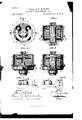
- Figure 1 is a plan view of our device with the upper part of the casing removed and a portion of the disk-ring armature broken out.
- Fig. 2 is a vertical section on line 2 2 of Fig. 1.
- Figs. 3 and 4 are elevations from opposite sides with the casing partially broken away.
- Fig. 5 is a diagrammatic view illustrating the electric connections, and
- Fig. 6 is a similar view illustrating a modification hereinafter referred to.
- A indicates the casing formed of two flanged portions a at, the lower one a having bindingposts a and each part having a screw-threaded neck a whereby the casing, united at the flanges and containing the valve and operating parts presently to be described, may be fitted to the inlet and outlet pipes (not shown) or may be inserted in and connected with any system of piping.
- the lower part a of the casing is provided with an annular shoulder a, which supports one end of the valved tube B, the upper end of which rests against the inner face of the upper part a of the casing, and at each end of the tube a packing may be placed to pre vent the escape of fluid into the casing outside of the tube.
- This tube is held centrally in the casing by its lower end fitting snugly into the enlarged seat above the shoulder a, and, if desired,the upper end might be similarly fitted.
- the valve B is hung on trunnions b in the tube, and an annular seat b is provided for the edges of the valve.
- One of the trunnions extends through and carries a pinion 17 outside of the tube, and this trunnion may, if desired, pass through a stuffingbox.
- E is the armature, in the shape of a diskring, extending over the projectingends of the four cores and pivoted upon a rod or bar 6, which, as shown, is mounted in the tube B.
- bracket F To the bottom of the casing a and in the same vertical plane with that of the pivots of the valve and a'rmature is secured a bracket F, having two contacts f f, insulated from each other, and a wire leads from each of the contacts to its respective compound magnet.
- a contact-brush G To the outer edge of the armature and at its pivotal center is secured a contact-brush G, and a wire leads from this brush to a battery X.
- I-I indicates a thermostat of any ordinary orpreferred kind, adapted to carry and switch an electric current.
- On opposite sides of the movable end of the thermostat are contacts h h, each connected with one of the compound magnets, and the fixed end of the thermostat is wired to the battery, which in the preferred form shown in Figs. 1 to 5, inclusive, is an open-circuit battery.
- an increase or decrease in temperature causes the thermostat to make contact at h or h and so complete the circuit through magnets O or D, respectively, and open or close the valve accordingly.
- Supposing, for instance, an increase of temperature causes a contact at h.
- This energizes magnet O, and the valve is so connected that it will be closed by the tilting of the armature, and this tilting immediately removes the brush G from contact f to contactf', and the circuit is broken atfand G, leaving the battery-circuit open.
- Fig. 6 illustrates a modification in which a closed-circuit battery is employed and the contact-plates and brush are omitted, and the wire from the battery is simply branched to connect with both compound magnets.
- the thermostat making connection at h or 77/, energizes one or the other of the magnets and operates the valve, it being understood that when the circuit of one magnet is closed, as at Q, the' circuit of the other magnet is broken at
- the binding-posts a (shown in Fig 2) are for the wires leading to the thermostat-contacts h and h and the battery.
- An electro-magnetic valve-controller consisting of a casing having a valved fluid-pas- .sage extending through it, two electro-mag nets, one located on each side of the passage, a pivoted armature surrounding the passage and acted upon by both magnets, two arms connected with the armature centered with its pivots, one of said arms carrying a rack and the other serving as an electrical contact, a. pinion connected with the valve-stem and engaging with said rack, a pair of contacts adapted to be engaged by said contact-arm, and electrical connections whereby first one magnet and then the other will be energized as the armature vibrates.
- witness whereof we have hereunto signed our names in the presence of two subscribing witnesses.
Landscapes
- Engineering & Computer Science (AREA)
- General Engineering & Computer Science (AREA)
- Mechanical Engineering (AREA)
- Magnetically Actuated Valves (AREA)
Description
(No Model.)
L. BELL 85 P. H. ROOT. ELEGTRIG VALVE CONTROLLER. No. 437,673. Patented Oct. 7, 1890.
IN VE II 7083 buis BY llllilllllllllLnIIIIIIIlII -fllllllllllll m! ml ll li l inLiiiillui:
eli lllilllilllllllllll n mnlllllhgllllllllll m" jTA/ESSES jgy/A A T TOR/YE Y.
UNITED STATES PATENT OFFICE,
LOUIS BELL AND FRANK II. ROOT, OF CHICAGO, ILLINOIS.
ELECTRlC VALVE-CONTROLLER.
SIPECIFICATION forming part of Letters Patent No. 437,673, dated October '7, 1890. Application filed June 18, 1890. Serial No. 355,819- (No model.)
To all whom it may concern.-
Beit known that we, LOUIS BELL and FRANK H. R001, citizens of the United States, residin g in Chicago, in the county of Cook and State of Illinois, have invented certain new and use ful Improvements in Electric Valve-Controllers, of which the following is a specification.
Our invention relates to devices for electrically controlling fiuid'valves; and our object is to produce a compact, simple, and efficient device of this class, and one that can be readily inserted as a coupling in a pipe.
Our invention consists in the construction and combination of parts, as hereinafter described and claimed.
In the accompanying drawings, Figure 1 is a plan view of our device with the upper part of the casing removed and a portion of the disk-ring armature broken out. Fig. 2 is a vertical section on line 2 2 of Fig. 1. Figs. 3 and 4 are elevations from opposite sides with the casing partially broken away. Fig. 5 is a diagrammatic view illustrating the electric connections, and Fig. 6 is a similar view illustrating a modification hereinafter referred to.
A indicates the casing formed of two flanged portions a at, the lower one a having bindingposts a and each part having a screw-threaded neck a whereby the casing, united at the flanges and containing the valve and operating parts presently to be described, may be fitted to the inlet and outlet pipes (not shown) or may be inserted in and connected with any system of piping.
The lower part a of the casing is provided with an annular shoulder a, which supports one end of the valved tube B, the upper end of which rests against the inner face of the upper part a of the casing, and at each end of the tube a packing may be placed to pre vent the escape of fluid into the casing outside of the tube. This tube is held centrally in the casing by its lower end fitting snugly into the enlarged seat above the shoulder a, and, if desired,the upper end might be similarly fitted. The valve B is hung on trunnions b in the tube, and an annular seat b is provided for the edges of the valve. One of the trunnions extends through and carries a pinion 17 outside of the tube, and this trunnion may, if desired, pass through a stuffingbox.
In the annular chamber, between the tube and easing, are secured the spools'c c and d d of the two compound magnets O and D, respectively, and the cores of the magnets are secured, as by screws Z, directly to the bottom of the metallic casing,whereby the latter forms the back yoke of the said compound magnets.
E is the armature, in the shape of a diskring, extending over the projectingends of the four cores and pivoted upon a rod or bar 6, which, as shown, is mounted in the tube B.
To the inner edge of the ring-armature and at the pivoted center thereof is secured the upper end of an arm e, which carries a segmental rack e engaging the pinion b of the valve. Therefore, since one of the compound magnets is located on one side of the pivotal center of the armature and the other compound magnet on the other side, an electric current directed through one or the other of the magnets will operate to open or close the valve.
To the bottom of the casing a and in the same vertical plane with that of the pivots of the valve and a'rmature is secured a bracket F, having two contacts f f, insulated from each other, and a wire leads from each of the contacts to its respective compound magnet.
To the outer edge of the armature and at its pivotal center is secured a contact-brush G, and a wire leads from this brush to a battery X.
I-I indicates a thermostat of any ordinary orpreferred kind, adapted to carry and switch an electric current. On opposite sides of the movable end of the thermostat are contacts h h, each connected with one of the compound magnets, and the fixed end of the thermostat is wired to the battery, which in the preferred form shown in Figs. 1 to 5, inclusive, is an open-circuit battery.
In operation, with the parts in an intermediate position, as indicated in Fig. 5, an increase or decrease in temperature causes the thermostat to make contact at h or h and so complete the circuit through magnets O or D, respectively, and open or close the valve accordingly. Supposing, for instance, an increase of temperature causes a contact at h. This energizes magnet O, and the valve is so connected that it will be closed by the tilting of the armature, and this tilting immediately removes the brush G from contact f to contactf', and the circuit is broken atfand G, leaving the battery-circuit open. ,Wh en a decrease of temperature causes the thermostat to make contact at h, the brush G, resting on plate f, allows one magnet D to be energized, thus opening the valve, transferring brush G to plate f, and again breaking the battery-circuit.
Fig. 6 illustrates a modification in which a closed-circuit battery is employed and the contact-plates and brush are omitted, and the wire from the battery is simply branched to connect with both compound magnets. In this form the thermostat, making connection at h or 77/, energizes one or the other of the magnets and operates the valve, it being understood that when the circuit of one magnet is closed, as at Q, the' circuit of the other magnet is broken at The binding-posts a (shown in Fig 2) are for the wires leading to the thermostat-contacts h and h and the battery.
Having thus described our invention, We claim- 1. In an electromagnetic valve-controller, the combination, with the valve, of a pair of compound magnets, a pivoted disk-ring armature for said magnets, an arm extending from the armature and having a rackat itsend, and a pinion carried by the valve and engaged by said rack, substantiallv as described.
2. An electro-magnetic valve-controller consisting of a casing having a valved fluid-pas- .sage extending through it, two electro-mag nets, one located on each side of the passage, a pivoted armature surrounding the passage and acted upon by both magnets, two arms connected with the armature centered with its pivots, one of said arms carrying a rack and the other serving as an electrical contact, a. pinion connected with the valve-stem and engaging with said rack, a pair of contacts adapted to be engaged by said contact-arm, and electrical connections whereby first one magnet and then the other will be energized as the armature vibrates. In witness whereof we have hereunto signed our names in the presence of two subscribing witnesses.
LOUIS BELL. FRANK H. ROOT. YVitnesses as to Bell:
WM. A. ROSENBAUM, THOMAS K. TRENCHARD. YVitnesses as to Root:
FRANK QUINN, H. W. CHRISTIAN.
Publications (1)
| Publication Number | Publication Date |
|---|---|
| US437673A true US437673A (en) | 1890-10-07 |
Family
ID=2506574
Family Applications (1)
| Application Number | Title | Priority Date | Filing Date |
|---|---|---|---|
| US437673D Expired - Lifetime US437673A (en) | Electric valve-controller |
Country Status (1)
| Country | Link |
|---|---|
| US (1) | US437673A (en) |
Cited By (1)
| Publication number | Priority date | Publication date | Assignee | Title |
|---|---|---|---|---|
| US3213871A (en) * | 1961-09-14 | 1965-10-26 | Int Harvester Co | Throttle control linkage |
-
0
- US US437673D patent/US437673A/en not_active Expired - Lifetime
Cited By (1)
| Publication number | Priority date | Publication date | Assignee | Title |
|---|---|---|---|---|
| US3213871A (en) * | 1961-09-14 | 1965-10-26 | Int Harvester Co | Throttle control linkage |
Similar Documents
| Publication | Publication Date | Title |
|---|---|---|
| US437673A (en) | Electric valve-controller | |
| US1292334A (en) | Fluid-flow indicator. | |
| US1475313A (en) | Circuit controller | |
| US1015204A (en) | Automatic temperature-regulator. | |
| US983861A (en) | Thermostatic alarm. | |
| US986707A (en) | Electric-circuit controller and alarm. | |
| US365600A (en) | Electric temperature-controlling device | |
| US1160422A (en) | Electric fire-engine system. | |
| US435898A (en) | johnson | |
| US769203A (en) | Electric signal. | |
| US2789784A (en) | Gas valve | |
| US1991807A (en) | Control system for plural valves | |
| US1229294A (en) | Automatic switch. | |
| US436219A (en) | Harry watson deeds | |
| US1193271A (en) | kuntz | |
| US1296976A (en) | Electrically-controlled apparatus. | |
| US996335A (en) | Fire-protection device. | |
| US1817090A (en) | Electrical water heating device | |
| US986355A (en) | Automatic fire-alarm. | |
| US417217A (en) | Electrical apparatus | |
| US352043A (en) | Circuit-closer | |
| US1237341A (en) | Electric car-heating system. | |
| US637232A (en) | Automatic fire-extinguisher. | |
| US560703A (en) | Charles l | |
| US1288968A (en) | Valve. |