US4373566A - Pneumatic radial tire having a reduced rolling resistance - Google Patents
Pneumatic radial tire having a reduced rolling resistance Download PDFInfo
- Publication number
- US4373566A US4373566A US06/270,206 US27020681A US4373566A US 4373566 A US4373566 A US 4373566A US 27020681 A US27020681 A US 27020681A US 4373566 A US4373566 A US 4373566A
- Authority
- US
- United States
- Prior art keywords
- rubber
- carcass
- base
- tire
- groove
- Prior art date
- Legal status (The legal status is an assumption and is not a legal conclusion. Google has not performed a legal analysis and makes no representation as to the accuracy of the status listed.)
- Expired - Fee Related
Links
Images


Classifications
-
- B—PERFORMING OPERATIONS; TRANSPORTING
- B60—VEHICLES IN GENERAL
- B60C—VEHICLE TYRES; TYRE INFLATION; TYRE CHANGING; CONNECTING VALVES TO INFLATABLE ELASTIC BODIES IN GENERAL; DEVICES OR ARRANGEMENTS RELATED TO TYRES
- B60C11/00—Tyre tread bands; Tread patterns; Anti-skid inserts
- B60C11/01—Shape of the shoulders between tread and sidewall, e.g. rounded, stepped or cantilevered
-
- B—PERFORMING OPERATIONS; TRANSPORTING
- B60—VEHICLES IN GENERAL
- B60C—VEHICLE TYRES; TYRE INFLATION; TYRE CHANGING; CONNECTING VALVES TO INFLATABLE ELASTIC BODIES IN GENERAL; DEVICES OR ARRANGEMENTS RELATED TO TYRES
- B60C9/00—Reinforcements or ply arrangement of pneumatic tyres
- B60C9/18—Structure or arrangement of belts or breakers, crown-reinforcing or cushioning layers
- B60C9/1835—Rubber strips or cushions at the belt edges
- B60C2009/1842—Width or thickness of the strips or cushions
-
- Y—GENERAL TAGGING OF NEW TECHNOLOGICAL DEVELOPMENTS; GENERAL TAGGING OF CROSS-SECTIONAL TECHNOLOGIES SPANNING OVER SEVERAL SECTIONS OF THE IPC; TECHNICAL SUBJECTS COVERED BY FORMER USPC CROSS-REFERENCE ART COLLECTIONS [XRACs] AND DIGESTS
- Y02—TECHNOLOGIES OR APPLICATIONS FOR MITIGATION OR ADAPTATION AGAINST CLIMATE CHANGE
- Y02T—CLIMATE CHANGE MITIGATION TECHNOLOGIES RELATED TO TRANSPORTATION
- Y02T10/00—Road transport of goods or passengers
- Y02T10/80—Technologies aiming to reduce greenhouse gasses emissions common to all road transportation technologies
- Y02T10/86—Optimisation of rolling resistance, e.g. weight reduction
-
- Y—GENERAL TAGGING OF NEW TECHNOLOGICAL DEVELOPMENTS; GENERAL TAGGING OF CROSS-SECTIONAL TECHNOLOGIES SPANNING OVER SEVERAL SECTIONS OF THE IPC; TECHNICAL SUBJECTS COVERED BY FORMER USPC CROSS-REFERENCE ART COLLECTIONS [XRACs] AND DIGESTS
- Y10—TECHNICAL SUBJECTS COVERED BY FORMER USPC
- Y10T—TECHNICAL SUBJECTS COVERED BY FORMER US CLASSIFICATION
- Y10T152/00—Resilient tires and wheels
- Y10T152/10—Tires, resilient
- Y10T152/10495—Pneumatic tire or inner tube
- Y10T152/10765—Characterized by belt or breaker structure
- Y10T152/1081—Breaker or belt characterized by the chemical composition or physical properties of elastomer or the like
-
- Y—GENERAL TAGGING OF NEW TECHNOLOGICAL DEVELOPMENTS; GENERAL TAGGING OF CROSS-SECTIONAL TECHNOLOGIES SPANNING OVER SEVERAL SECTIONS OF THE IPC; TECHNICAL SUBJECTS COVERED BY FORMER USPC CROSS-REFERENCE ART COLLECTIONS [XRACs] AND DIGESTS
- Y10—TECHNICAL SUBJECTS COVERED BY FORMER USPC
- Y10T—TECHNICAL SUBJECTS COVERED BY FORMER US CLASSIFICATION
- Y10T152/00—Resilient tires and wheels
- Y10T152/10—Tires, resilient
- Y10T152/10495—Pneumatic tire or inner tube
- Y10T152/10819—Characterized by the structure of the bead portion of the tire
- Y10T152/10837—Bead characterized by the radial extent of apex, flipper or chafer into tire sidewall
-
- Y—GENERAL TAGGING OF NEW TECHNOLOGICAL DEVELOPMENTS; GENERAL TAGGING OF CROSS-SECTIONAL TECHNOLOGIES SPANNING OVER SEVERAL SECTIONS OF THE IPC; TECHNICAL SUBJECTS COVERED BY FORMER USPC CROSS-REFERENCE ART COLLECTIONS [XRACs] AND DIGESTS
- Y10—TECHNICAL SUBJECTS COVERED BY FORMER USPC
- Y10T—TECHNICAL SUBJECTS COVERED BY FORMER US CLASSIFICATION
- Y10T152/00—Resilient tires and wheels
- Y10T152/10—Tires, resilient
- Y10T152/10495—Pneumatic tire or inner tube
- Y10T152/10819—Characterized by the structure of the bead portion of the tire
- Y10T152/10846—Bead characterized by the chemical composition and or physical properties of elastomers or the like
-
- Y—GENERAL TAGGING OF NEW TECHNOLOGICAL DEVELOPMENTS; GENERAL TAGGING OF CROSS-SECTIONAL TECHNOLOGIES SPANNING OVER SEVERAL SECTIONS OF THE IPC; TECHNICAL SUBJECTS COVERED BY FORMER USPC CROSS-REFERENCE ART COLLECTIONS [XRACs] AND DIGESTS
- Y10—TECHNICAL SUBJECTS COVERED BY FORMER USPC
- Y10T—TECHNICAL SUBJECTS COVERED BY FORMER US CLASSIFICATION
- Y10T152/00—Resilient tires and wheels
- Y10T152/10—Tires, resilient
- Y10T152/10495—Pneumatic tire or inner tube
- Y10T152/10855—Characterized by the carcass, carcass material, or physical arrangement of the carcass materials
- Y10T152/10864—Sidewall stiffening or reinforcing means other than main carcass plies or foldups thereof about beads
Definitions
- This invention relates to a pneumatic radial tire having a reduced rolling resistance and particularly suitable for a passenger car.
- a radial tire comprises a carcass body reinforcement which consists of a toroidal carcass composed of plies including radially arranged cords, that is, cords arranged in a radial plane inclusive of a rotary axis of the tire or a plane inclined at a small angle to the radial plane and crossed therewith. Also a plurality of belt layers are superimposed about the crown portion of the carcass and include cords inclined at an angle of a range between 60° and 80° to the radial plane of the tire, the cords of adjacent belt layers being crossed with each other.
- a bead reinforcement consists of the lower portion of the toroidal carcass wound around a bead core to form a turn-up portion. The carcass body reinforcement and bead reinforcement are covered with outer rubber layer of the tread portion and side portion made integral with the bead portion by vulcanization.
- the rolling resistance of the tire produced when a vehicle provided with the above mentioned radial tire runs on a flat paved road without inclination is produced mainly due to the internal loss caused by flexure of the tire formed during rotation of tire and the frictional loss between the tire and the road surface.
- the rate of the internal loss taken in the above two losses is large has been well known in the art.
- the tire must display different abilities in dependence with its different positions such as the tread portion, side portion or the like.
- the rubber having a low loss modulus of elasticity is applied to the tread portion and is maximized in amount, hence tending to give a maximum contribution to the ability of the tire, the frictional coefficient with the road surface considerably decreases to deteriorate the anti skid property and breaking property, thereby restricting the safety of the tire.
- Means for reducing the rolling resistance of the tire comprising an annular groove arranged in the outer rubber layer of the shoulder of the tire and circumferentially extending along the tire has been proposed and described in U.S. Pat. No. 3,253,635.
- the annular groove is operative to interrupt the tread portion and the side portion which are different in operation as an oscillatory system of the tire when it runs from each other.
- Such kind of tire is the same in construction as a tire including nibbling groove which has been well known in the art and hardly displays an effect of reducing the rolling resistance.
- the tire including a nibbling groove is a tire which is provided at its shoulder portion with a deep annular groove circumferentially extending the tire and operative to easily deform transversely the tread portion side edge for the purpose of reducing the resistance that tends to be produced when the tire rides over in the lengthwise direction of projections slightly raised from the road surface such as a rail for street car provided along the road.
- the rolling resistance of the tire exerts a direct influence upon the driving force of automobile, so that there is an urgent requirement in the tire manufacturing field to reduce considerable the rolling resistance of the tire in compliance with the requirements of economizing energy.
- An object of the invention is to provide a pneumatic radial tire having a reduced rolling resistance, which can fully satisfy the above mentioned desire required in the tire manufacturing field.
- a feature of the invention is in a pneumatic radial tire comprising a toroidal carcass including radially arranged cords, a belt layer superimposed about the crown portion of the carcass and including a plurality of cord layers, each cord being inclined at an angle within a range between 60° and 80° with respect to the radial plane of the tire and each cord of adjacent cord layers being crossed with each other.
- a bead core has the lower end of the toroidal carcass is wound around it to form a turn-up portion.
- a side rubber outwardly covers a side portion and bead portion of the toroidal carcass, and a tread rubber outwardly covers the crown portion of the carcass inclusive of the belt layer and forming a joint portion with the side rubber.
- a relatively thin base rubber is disposed directly below the joint portion between the side rubber and the tread rubber and is superimposed about the outer surface of the carcass and belt layer and made integral therewith, and a rubber filler is disposed on the bead core and sandwiched between the carcass and its turn-up portion.
- a stress relieving groove is composed of a depression facing toward the base rubber at a position near the joint portion between the side rubber and the tread rubber.
- the base rubber has a resilience which is higher than those of the tread rubber and side rubber.
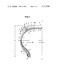
- FIG. 1 is a diagrammatic sectional view of left-half of one embodiment of a pneumatic radial tire having a reduced rolling resistance according to the invention
- FIG. 2 is a diagrammatic sectional view of left-half of a second embodiment of a pneumatic radial tire having a reduced rolling resistance according to the invention.
- FIG. 3 is a diagrammatic sectional view of left-half of a third embodiment of a pneumatic radial tire having a reduced rolling resistance according to the invention.
- the tire shown in FIG. 1 is mainly composed of a tread T located at the center portion of the tire and a side portion S projecting outwardly from two side edges E, E of the tread T.
- FIG. 1 shows left-half of the tire for ease of illustration, but it is a matter of course that the tire is symmetrical with respect to the equatorial line O--O.
- Each portion of the tire is reinforced by a toroidal carcass 1 composed of plies formed of textile cords represented by polyester, nylon and rayon or the like and arranged in a radial plane of the tire, that is, a plane perpendicular or substantially perpendicular to the equatorial line O--O.
- the lower end of the toroidal carcass 1 is wound around a bead core 2 from the inside toward the outside thereof to form a turn-up portion 1'.
- FIG. 1 shows the carcass 1 composed of one ply only. But, the carcass 1 may be composed of two or more than two plies in dependence with the kind of cords and the use of the tire.
- the rubber filler F is formed of a rubber having a considerably high dynamic modulus of elasticity whose value preferably lies within a range between 300 kg/cm 2 and 1,5000 kg/cm 2 .
- composition of the rubber filler having the above mentioned physical property is as follows. 100 parts by weight of a vulcanizable rubber selected from the group consisting of natural rubber, diene rubber, diene copolymer rubber and blend rubber containing the above mentioned rubber with any ratio is compounded with 5 to 30 parts by weight, preferably 8 to 30 parts by weight, more preferably 15 to 25 parts by weight of thermo-setting resin and with 0.5 to 5 parts by weight of a hardening agent for the thermo-setting resin, for example, hexamethylene tetramine.
- a vulcanizable rubber selected from the group consisting of natural rubber, diene rubber, diene copolymer rubber and blend rubber containing the above mentioned rubber with any ratio is compounded with 5 to 30 parts by weight, preferably 8 to 30 parts by weight, more preferably 15 to 25 parts by weight of thermo-setting resin and with 0.5 to 5 parts by weight of a hardening agent for the thermo-setting resin, for example, hexamethylene tetramine.
- reinforcing material, filling agent, anti-ageing agent, vulcanization accelerating agent, activating agent, softening agent, plasticizer, adhesive agent or the like used, as the conventional rubber compounding agent other than the above mentioned compounding agents may suitably be compounded with the above mentioned rubber.
- thermo-setting resin use may be made of phenol resin, cresol resin, or denatured resin denatured from any ratio of the above mentioned resin, for example, cashew denatured phenol resin, cashew denatured cresol resin, cresol denatured phenol resin, oil denatured phenol or cresol resin denatured with an oil such as linolic acid, linolenic acid, oleic acid or the like, or alkyl benzene denatured phenol or cresol resin denatured with alkyl benzene such as xylene, mesitylene or the like, or phenol or cresol resin denatured with rubber such as nitrile rubber or the like.
- an oil such as linolic acid, linolenic acid, oleic acid or the like
- alkyl benzene denatured phenol or cresol resin denatured with alkyl benzene such as xylene, mesitylene or the like
- the crown portion C of the toroidal carcass 1 is reinforced by a belt layer 3 superimposed about and extending over the total width of the tread portion T.
- the belt layer 3 is composed of cord layers 3-1 and 3-2 formed of metal cords or textile cords having a high modulus of elasticity and inclined at an angle within a range between 60° and 80° with respect to the radial plane of the tire. These cord layers 3-1 and 3-2 being superimposed one upon the other such that the cords of the cord layer 3-1 are crossed with the cords of the cord layer 3-2 through the equatorial line O--O of the tire.
- the belt cord layer use may be made of three or more than three cord layers superimposed one upon the other. Alternatively, ply end portions may be folded to reinforce the end portion of the belt layer.
- the total peripheral surface of the carcass 1 is covered at its outside with an outer rubber layer 4 and at its inside with an inner liner 5.
- the outer rubber layer 4 is divided into a side rubber 6 having an excellent fatigue resistant property against extensible strain repeatedly subjected to the side portion S when the tire runs and a tread rubber T having an excellent wear resistant and anti-skid property and located at the tread portion T.
- the side rubber 6 is made integral with the tread rubber 7 at the joint portion 9 located at the shoulder 8 slightly outside the side edge E of the tread portion T.
- the tread portion T is provided with ribs or blocks (not shown) which are divided by means of various kinds of tread grooves, a skid base having a given gauge being remained near the belt layer 3 as in the conventional manner.
- a relatively thin base rubber 10 arranged directly below the joint portion 9 of the side rubber 6 and superimposed about and made integral with the outer surface of the toroidal carcass 1 and belt layer 3.
- the base rubber 10 has a resilience which is higher than those of the side rubber 6 and tread rubber 7.
- the side rubber 6 is provided at a position near the joint portion 9 with the tread rubber 7 with a stress relieving groove 11 depressed toward the base rubber 10.
- the base rubber 10 is made slightly thinner than the side rubber 6 and tread rubber 7 and the side edge facing the bead portion B is made wedge shaped and interposed between the side rubber 6 and the carcass 1.
- the base rubber 10 has a center portion between the tread rubber 7 and the carcass 1 and the side edge facing the crown center is also made wedge shaped and interposed between the tread rubber 7 and belt layer 3.
- the base rubber 10 has a loss modulus of elasticity of 2.0 to 12 kg/cm 2 which is suitable for attaining an object of the present invention.
- the stress relieving groove 11 is made V-shaped in section and its base is rounded and is arranged such that it is depressed toward the base rubber 10 at a position near the joint portion 9 between the side rubber 6 and the tread rubber 7. More particularly, one sidewall of the stress relieving groove 11 is located near the joint portion 9 of the rubber and the base of the stress relieving groove 11 is spaced apart from the base rubber 10 by a thin layer of the side rubber 6.
- a center line of the stress relieving groove 11, that is, a straight line J for bisecting the angle formed between opposed groove sidewalls is inclined at an angle ⁇ with respect to a normal line N--N which intersects the center line J at the groove base and inclined toward the crown portion of the tire. It is preferable to make the inclined angle ⁇ within a range between 30° and 50° in order to attain the object of the present invention.
- the depth g of the stress relieving groove 11 measured along the normal line N--N drawn at the carcass line is made about 25% to 50% of the total rubber thickness h measured along the normal line N--N. If the groove depth is relatively shallow, the gauge of the base rubber 10 opposed to the groove base is made correspondingly thick. Conversely, if the groove depth is deep, the gauge of the base rubber 10 is made thin.
- the width of the stress relieving groove 11 must be made wide so that the groove does not substantially close even when the tire is subjected to deformation under load when it runs.
- the stress relieving groove 11 is shown at one side only of the tire, but a plurality of relatively narrow grooves may be arranged side by side along the circumference of the tire. It is preferable to make the width of the stress relieving groove (the total width of these grooves if the provision is made of a plurality of stress relieving grooves side by side) within a range between 2 mm and 6 mm measured along the opening of the groove dependent on the tire side.
- the width of the stress relieving groove considerably larger than the above mentioned limited range has no effective function.
- the invention is applied to a tire in which a ratio of the tire sectional height H to the tire maximum width W is 0.5 to 0.8 and the portion of the side edge E of the tread portion T is round, that is, a so-called round shoulder tire.
- the independent left and right base rubbers 10, 10 shown in FIG. 1 are connected with each other on the belt layer 3 to make a single annular base rubber 10' interposed between the belt layer 3 and the tread rubber 7.
- that portion of the base rubber 10' which lies at the side edge E of the tread portion T is interposed between the toroidal carcass 1 and the tread rubber 7 and that portion of the base rubber 10' which extends from the joint portion 9 between the tread and the side rubber and passes directly below the stress relieving groove 11 to the bead portion B is made wedge shaped and inserted between the toroidal carcass 1 and the side rubber 6.
- the side edge of the base rubber 10" facing the crown center is made wedge shaped and inserted between the end edge 12 of the belt layer 3 and the toroidal carcass 1. This construction is different from that of the embodiment shown in FIG. 1.
- test tires each having a size 185/70SR13 were manufactured.
- the test tire constructed according to the invention was compared with the test tire having the conventional construction with respect to the rolling resistance.
- the carcass 1 was composed of two polyester cord layers of 1,500 d/2 and radially arranged.
- the belt layer 3 was composed of two steel cord plies inclined at 71° with respect to the radial plane and crossed with each other between adjacent plies.
- the side rubber 6, tread rubber 7, base rubber 10 and stress relieving groove 11 at the shoulder portion of the tire were arranged as shown in FIG. 1.
- the base rubber gauge directly below the stress relieving groove 11 was made 1.5 mm.
- test tire according to the invention A was compared with the test tire B having the conventional construction.
- the construction of the test tire according to the invention A and the conventional test tire B is shown in the following Table 1 and an example of rubber composition of the main portions of these test tires and the physical property thereof are shown in the following Table 2.
- the pneumatic radial tire according to the invention is capable of effectively reducing the rolling resistance of the tire without deteriorating the properties generally required for such tire.
Landscapes
- Engineering & Computer Science (AREA)
- Mechanical Engineering (AREA)
- Tires In General (AREA)
Abstract
Description
              TABLE 1
______________________________________
                     Kind of Tire
Constitutional Element A     B
______________________________________
Stress relieving groove (11)
                       *o    **o
Base rubber (10)       o     x
______________________________________
 Note:
 In the above table, symbol o means that the tire is provided with the
 stress relieving groove 11 or base rubber 10.
 Symbol x means that the tire is not provided with these constitutional
 elements.
 Symbol * means that the groove center line is inclined from the normal
 line at an angle α of 40.5°.
 Symbol ** means that the groove center line coincides with the normal
 line, that is, the inclined angle α is zero.
              TABLE 2
______________________________________
             Tread Side     Base    Rubber
             rubber
                   rubber   rubber  filler
______________________________________
Rubber composition
(parts by weight)
Natural rubber --      60       80    100
Styrene-butadiene
               80      --       --    --
copolymer rubber
Polybutadiene rubber
               20      40       20    --
Carbon black
ISAF           75      --       --    --
HAF            --      --       38    75
FEF            --      48       --    --
Phenol resin   --      --       --    24
Aromatic oil   35      13       4     5
Sulphur        1.8     2        2.5   6
Physical property
(after vulcanization)
Resilience (%) 38      53       70    45
Loss modulus of
               30      8        8     --
elasticity (kg/cm.sup.2)
               30      8        8     --
Dynamic modulus of
               100     50       --    980
elasticity (kg/cm.sup.2)
______________________________________
 Note
 1. Resilience of a rubber sample of 2 mm × 8 mm × 4 ± 0.1
 mm was measured by a Dunlop tripso resilience tester made by Toyo
 Seisakusho Co. in Japan at a normal temperature with the aid of a hammer
 having a weight of 60 g.
 2. The loss modulus of elasticity of a strip shaped sample of a width 5 m
 × depth 2 mm was obtained by calculation by measuring the loss
 coefficient and dynamic modulus of elasticity at a temperature of
 25° C. with a number of oscillations of 50 Hz and dynamic strain o
 1% by means of a viscoelastic spectrometer made by Iwamoto Seisakusho Co.
 in Japan.
              TABLE 3
______________________________________
              Kind of Tire
Speed           A         B
______________________________________
 50 km/h (hour) 3.7 kg (123)
                          4.8 kg (100)
100 km/h (hour) 4.2 kg (119)
                          5.2 kg (100)
150 km/h (hour) 7.5 kg (109)
                          8.2 kg (100)
______________________________________
Claims (8)
Applications Claiming Priority (2)
| Application Number | Priority Date | Filing Date | Title |
|---|---|---|---|
| JP8089280A JPS577703A (en) | 1980-06-17 | 1980-06-17 | Pneumatic radial tire with reduced rolling resistance |
| JP55-80892 | 1980-06-17 |
Publications (1)
| Publication Number | Publication Date |
|---|---|
| US4373566A true US4373566A (en) | 1983-02-15 |
Family
ID=13731003
Family Applications (1)
| Application Number | Title | Priority Date | Filing Date |
|---|---|---|---|
| US06/270,206 Expired - Fee Related US4373566A (en) | 1980-06-17 | 1981-06-03 | Pneumatic radial tire having a reduced rolling resistance |
Country Status (4)
| Country | Link |
|---|---|
| US (1) | US4373566A (en) |
| JP (1) | JPS577703A (en) |
| CA (1) | CA1141276A (en) |
| GB (1) | GB2077671B (en) |
Cited By (9)
| Publication number | Priority date | Publication date | Assignee | Title |
|---|---|---|---|---|
| US5154217A (en) * | 1986-11-21 | 1992-10-13 | The Yokohama Rubber Co., Ltd. | Heavy-duty pneumatic tire preventing belt separation |
| US5248357A (en) * | 1990-07-25 | 1993-09-28 | Sumitomo Rubber Industries Limited | Process for assembling a green tire |
| US5417267A (en) * | 1991-08-20 | 1995-05-23 | Bridgestone Corporation | Pneumatic tires including foamed rubber layer to reduce noise |
| EP1074404A1 (en) * | 1999-07-21 | 2001-02-07 | The Yokohama Rubber Co., Ltd. | Pneumatic tire for passenger cars |
| US6247512B1 (en) | 1996-09-03 | 2001-06-19 | Michelin Recherche Et Technique S.A. | Tire having tread portion with rubber to control wear |
| US20040261926A1 (en) * | 2003-06-24 | 2004-12-30 | Fahri Ozel | Truck tire with cap/base construction tread |
| WO2006066602A1 (en) * | 2004-12-21 | 2006-06-29 | Pirelli Tyre S.P.A. | Heavy load vehicle tire |
| CN101488442B (en) * | 2008-01-18 | 2010-12-01 | 湖州和华照明电器有限公司 | Novel halogen strip lamp |
| US10775272B2 (en) * | 2017-12-05 | 2020-09-15 | Ali Samadi | Rubber footprint and rolling resistance measurement |
Families Citing this family (14)
| Publication number | Priority date | Publication date | Assignee | Title |
|---|---|---|---|---|
| JPS58126204A (en) * | 1982-01-21 | 1983-07-27 | Sumitomo Rubber Ind Ltd | Radial tyre for heavy car |
| JPS58121701U (en) * | 1982-02-13 | 1983-08-19 | 住友ゴム工業株式会社 | Retreaded tires |
| IT1151557B (en) * | 1982-04-30 | 1986-12-24 | Pirelli | IMPROVEMENTS TO THE TIRE BELT STRUCTURES FOR VEHICLES |
| BR8400317A (en) * | 1983-02-09 | 1985-02-12 | Goodyear Tire & Rubber | AVIATION TIRE |
| JPS6038211A (en) * | 1983-08-09 | 1985-02-27 | Sumitomo Rubber Ind Ltd | Radial tire |
| JPS61141867A (en) * | 1984-12-14 | 1986-06-28 | Tsuboya Seizaburo | Preparation of salted salmon roe |
| JPS63130407A (en) * | 1986-11-20 | 1988-06-02 | Sumitomo Rubber Ind Ltd | Heavy load pneumatic tyre with reduced rolling resistance |
| WO1988005018A1 (en) * | 1986-12-25 | 1988-07-14 | Kabushikikaisha Itoki Kosakusho | Automatic storing and retrieving apparatus for articles |
| JP2573264B2 (en) * | 1987-12-09 | 1997-01-22 | 住友ゴム工業 株式会社 | Radial tires for heavy loads |
| FR2775219B1 (en) | 1998-02-20 | 2000-03-31 | Michelin & Cie | JOINING A TREAD BELT WITH THE SIDES OF A TIRE |
| JP2001121919A (en) * | 1999-10-26 | 2001-05-08 | Bridgestone Corp | Pneumatic radial tire |
| JP5018022B2 (en) * | 2006-11-07 | 2012-09-05 | 横浜ゴム株式会社 | Pneumatic tire |
| EP2392479B1 (en) * | 2009-01-29 | 2016-12-07 | Bridgestone Corporation | Pneumatic tire |
| EP4183595A1 (en) * | 2021-11-19 | 2023-05-24 | The Goodyear Tire & Rubber Company | A tire having an improved shoulder design |
Citations (7)
| Publication number | Priority date | Publication date | Assignee | Title |
|---|---|---|---|---|
| US3253635A (en) * | 1963-04-12 | 1966-05-31 | Michelin & Cie | Pneumatic tire casings |
| GB1067856A (en) * | 1963-07-19 | 1967-05-03 | Pneumatiques Caoutchouc Mfg | Tyre for heavy duty vehicles |
| DE2403924A1 (en) * | 1973-01-29 | 1974-08-08 | Pneumatiques Caoutchouc Mfg | PNEUMATIC TIRES FOR MOTOR VEHICLES |
| US4006766A (en) * | 1970-12-29 | 1977-02-08 | Bridgestone Tire Company Limited | Radial tires |
| US4274462A (en) * | 1978-04-06 | 1981-06-23 | Bridgestone Tire Co., Ltd. | Pneumatic tire having an improved resistance against heat build-up employing syndiotactic-1,2-polybutadiene fibers in tread base rubber |
| JPS5679004A (en) * | 1979-11-30 | 1981-06-29 | Yokohama Rubber Co Ltd:The | Pneumatic tire |
| US4285381A (en) * | 1979-06-18 | 1981-08-25 | Sumitomo Rubber Industries, Ltd. | Curable composition for hard rubber and the use thereof |
-
1980
- 1980-06-17 JP JP8089280A patent/JPS577703A/en active Pending
-
1981
- 1981-06-03 US US06/270,206 patent/US4373566A/en not_active Expired - Fee Related
- 1981-06-03 CA CA000378933A patent/CA1141276A/en not_active Expired
- 1981-06-17 GB GB8118689A patent/GB2077671B/en not_active Expired
Patent Citations (7)
| Publication number | Priority date | Publication date | Assignee | Title |
|---|---|---|---|---|
| US3253635A (en) * | 1963-04-12 | 1966-05-31 | Michelin & Cie | Pneumatic tire casings |
| GB1067856A (en) * | 1963-07-19 | 1967-05-03 | Pneumatiques Caoutchouc Mfg | Tyre for heavy duty vehicles |
| US4006766A (en) * | 1970-12-29 | 1977-02-08 | Bridgestone Tire Company Limited | Radial tires |
| DE2403924A1 (en) * | 1973-01-29 | 1974-08-08 | Pneumatiques Caoutchouc Mfg | PNEUMATIC TIRES FOR MOTOR VEHICLES |
| US4274462A (en) * | 1978-04-06 | 1981-06-23 | Bridgestone Tire Co., Ltd. | Pneumatic tire having an improved resistance against heat build-up employing syndiotactic-1,2-polybutadiene fibers in tread base rubber |
| US4285381A (en) * | 1979-06-18 | 1981-08-25 | Sumitomo Rubber Industries, Ltd. | Curable composition for hard rubber and the use thereof |
| JPS5679004A (en) * | 1979-11-30 | 1981-06-29 | Yokohama Rubber Co Ltd:The | Pneumatic tire |
Cited By (12)
| Publication number | Priority date | Publication date | Assignee | Title |
|---|---|---|---|---|
| US5154217A (en) * | 1986-11-21 | 1992-10-13 | The Yokohama Rubber Co., Ltd. | Heavy-duty pneumatic tire preventing belt separation |
| US5248357A (en) * | 1990-07-25 | 1993-09-28 | Sumitomo Rubber Industries Limited | Process for assembling a green tire |
| US5417267A (en) * | 1991-08-20 | 1995-05-23 | Bridgestone Corporation | Pneumatic tires including foamed rubber layer to reduce noise |
| US6247512B1 (en) | 1996-09-03 | 2001-06-19 | Michelin Recherche Et Technique S.A. | Tire having tread portion with rubber to control wear |
| EP1074404A1 (en) * | 1999-07-21 | 2001-02-07 | The Yokohama Rubber Co., Ltd. | Pneumatic tire for passenger cars |
| US20040261926A1 (en) * | 2003-06-24 | 2004-12-30 | Fahri Ozel | Truck tire with cap/base construction tread |
| US7028734B2 (en) | 2003-06-24 | 2006-04-18 | The Goodyear Tire & Rubber Company | Truck tire with cap/base construction tread |
| WO2006066602A1 (en) * | 2004-12-21 | 2006-06-29 | Pirelli Tyre S.P.A. | Heavy load vehicle tire |
| US20080264543A1 (en) * | 2004-12-21 | 2008-10-30 | Fabio Montanaro | Heavy Load Vehicle Tire |
| CN101076458B (en) * | 2004-12-21 | 2010-09-08 | 倍耐力轮胎股份公司 | Heavy load vehicle tyre |
| CN101488442B (en) * | 2008-01-18 | 2010-12-01 | 湖州和华照明电器有限公司 | Novel halogen strip lamp |
| US10775272B2 (en) * | 2017-12-05 | 2020-09-15 | Ali Samadi | Rubber footprint and rolling resistance measurement |
Also Published As
| Publication number | Publication date |
|---|---|
| GB2077671B (en) | 1984-05-02 |
| JPS577703A (en) | 1982-01-14 |
| CA1141276A (en) | 1983-02-15 |
| GB2077671A (en) | 1981-12-23 |
Similar Documents
| Publication | Publication Date | Title |
|---|---|---|
| US4373566A (en) | Pneumatic radial tire having a reduced rolling resistance | |
| US4766940A (en) | Pneumatic radial tire having an excellent steering stability | |
| CA1120843A (en) | Pneumatic radial tires for passenger cars having a low rolling resistance | |
| JP3372311B2 (en) | Radial ply pneumatic tire | |
| EP0206679B1 (en) | Reinforced bead structure for heavy duty tyre | |
| US5295526A (en) | Run-flat pneumatic radial tire | |
| EP0719662B1 (en) | Pneumatic tyre | |
| CA1113357A (en) | Radial-ply tire | |
| US4273177A (en) | Pneumatic radial tire with folded ply breaker having soft cushion surrounding breaker edge | |
| US4265288A (en) | Pneumatic safety tire with excellent long-running ability after puncture employing rubber having specifically defined properties for sidewall inserts and tread | |
| US6510883B2 (en) | Pneumatic vehicle tire including rubber reinforcing plies in side wall regions | |
| JPH10175403A (en) | Pneumatic tire | |
| JP2002500589A (en) | Run-flat tire with improved carcass | |
| US4047552A (en) | Pneumatic radial tire for heavy load vehicles | |
| CA2086638C (en) | Pneumatic tire | |
| US6536494B1 (en) | Pneumatic vehicle tire | |
| US11577554B2 (en) | Tire having reinforced sidewalls | |
| JPH02185802A (en) | Pneumatic radial tire | |
| US6626216B2 (en) | Pneumatic tire having hollow particles in base rubber | |
| US4842033A (en) | Pneumatic tire having gum strips encasing a carcass turnup | |
| EP1577122A1 (en) | Run-flat tire | |
| CA1228282A (en) | Pneumatic radial tire having a good high-speed running performance | |
| US4140166A (en) | Pneumatic radial tire | |
| EP0698513B1 (en) | Pneumatic radial tires | |
| EP0209125A2 (en) | Pneumatic tire having radially varying tread composition |
Legal Events
| Date | Code | Title | Description |
|---|---|---|---|
| AS | Assignment |
Owner name: BRIDGESTONE TIRE COMPANY LIMITED 10-1, KYOBASHI 1- Free format text: ASSIGNMENT OF ASSIGNORS INTEREST.;ASSIGNORS:HIRAKAWA, HIROSHI;SATO, AKIO;TAKUSAGAWA, TAKASHI;AND OTHERS;REEL/FRAME:004046/0800 Effective date: 19810514 Owner name: BRIDGESTONE TIRE COMPANY LIMITED, JAPAN Free format text: ASSIGNMENT OF ASSIGNORS INTEREST;ASSIGNORS:HIRAKAWA, HIROSHI;SATO, AKIO;TAKUSAGAWA, TAKASHI;AND OTHERS;REEL/FRAME:004046/0800 Effective date: 19810514 |
|
| FEPP | Fee payment procedure |
Free format text: PAYOR NUMBER ASSIGNED (ORIGINAL EVENT CODE: ASPN); ENTITY STATUS OF PATENT OWNER: LARGE ENTITY |
|
| MAFP | Maintenance fee payment |
Free format text: PAYMENT OF MAINTENANCE FEE, 4TH YEAR, PL 96-517 (ORIGINAL EVENT CODE: M170); ENTITY STATUS OF PATENT OWNER: LARGE ENTITY Year of fee payment: 4 |
|
| FEPP | Fee payment procedure |
Free format text: MAINTENANCE FEE REMINDER MAILED (ORIGINAL EVENT CODE: REM.); ENTITY STATUS OF PATENT OWNER: LARGE ENTITY |
|
| LAPS | Lapse for failure to pay maintenance fees | ||
| STCH | Information on status: patent discontinuation |
Free format text: PATENT EXPIRED DUE TO NONPAYMENT OF MAINTENANCE FEES UNDER 37 CFR 1.362 |
|
| FP | Lapsed due to failure to pay maintenance fee |
Effective date: 19910217 |