US4373372A - Apparatus for assembling electrical cables to electrical connectors - Google Patents
Apparatus for assembling electrical cables to electrical connectors Download PDFInfo
- Publication number
- US4373372A US4373372A US06/167,945 US16794580A US4373372A US 4373372 A US4373372 A US 4373372A US 16794580 A US16794580 A US 16794580A US 4373372 A US4373372 A US 4373372A
- Authority
- US
- United States
- Prior art keywords
- cable
- roller members
- members
- cable clamp
- connector
- Prior art date
- Legal status (The legal status is an assumption and is not a legal conclusion. Google has not performed a legal analysis and makes no representation as to the accuracy of the status listed.)
- Expired - Lifetime
Links
Images

Classifications
-
- H—ELECTRICITY
- H01—ELECTRIC ELEMENTS
- H01R—ELECTRICALLY-CONDUCTIVE CONNECTIONS; STRUCTURAL ASSOCIATIONS OF A PLURALITY OF MUTUALLY-INSULATED ELECTRICAL CONNECTING ELEMENTS; COUPLING DEVICES; CURRENT COLLECTORS
- H01R43/00—Apparatus or processes specially adapted for manufacturing, assembling, maintaining, or repairing of line connectors or current collectors or for joining electric conductors
Definitions
- This invention is directed to a hand operated tool for assembling electrical cables to an electrical connector. More particularly, the exemplary embodiment of the invention is directed to an apparatus for crimping a cable clamp means, hereinafter sometimes referred to as clamp, onto a cable in position for termination with conductive contact means, sometimes referred to herein as contacts, on the connector, the cable clamp means being associated with the connector itself.
- a cable clamp means hereinafter sometimes referred to as clamp
- contacts conductive contact means
- a continuing problem is to provide tools or apparatus for simply performing various operations on electrical wires or cables, such as connecting, terminating or crimping the wires or cables to electrical connectors or terminals, and for otherwise handling the wires in a simple and efficient manner during volume manufacturing.
- This is particularly true for multi-conductor cables which have numerous individual wires for termination to plural contacts of an electrical connector.
- connectors as the well-known Amphenol Series 57 and 157 electrical connectors
- an elongated connector body is provided with receptacle means including a plurality of linearly oriented slots or notches which are adapted for receiving individual contacts.
- the contacts may be capable of being soldered, or connected by insulation displacement techniques to the individual wires of an electrical cable. Considerable manipulation of the numerous individual wires is required, and means often and provided on the assembly tool itself for clamping or holding the cable while the individual wires are terminated to the connector contacts.
- an object of the present invention is to provide an apparatus in the form of a hand tool for assembling electrical cables to electrical connectors, including means for crimping a cable clamp portion of the connector onto a cable to provide strain relief therefor.
- a base is provided with a pair of opposed jaw members rotatably mounted on the base for movement about generally parallel, spaced axes of rotation toward and away from a connector to engage the cable clamp means thereof for clamping a cable to provide strain relief therefor.
- An actuator member is mounted on one of the jaw members for rotating the jaw member, and direct-drive link means interconnects both jaw members for conjoint rotation thereof in opposite directions toward and away from the cable clamp means in response to movement of the actuator member.
- the jaws are formed by opposed notches in the peripheries of a pair of roller members, and the actuator member comprises a hand lever fixed at one end thereof to one of the roller members so as to extend outwardly therefrom in a plane generally perpendicular to the axes of rotation of the roller members.
- Spring means interconnects the roller members for biasing the members in an opening direction away from the cable clamp means.
- Stop means is provided between the base and one of the roller members for limiting movement of the roller members in a closing direction to preclude excessive crimping forces on the cable clamp means.
- the link means comprises a rigid, slidable plate extending directly between the roller members in driving relationship therewith.
- the rigid plate is disposed within opposed, facing grooves in the peripheries of the roller members.
- Back-up spring means is disposed in one of the grooves for biasing the slidable plate into the other of the grooves.
- the link means comprises a flexible leaf spring extending between the roller members in a direct driving relationship therewith, and slidably received within the opposed, facing grooves in the peripheries of the roller members.
- the invention therefore, provides a versatile, self-contained hand tool for crimping cable clamps, in the form of a separate apparatus for use in the field, as a bench tool, or for like applications.
- FIG. 1 is a perspective view of an apparatus for assembling electrical cables, or the like, to an electrical connector, embodying the concepts of the present invention, with a portion of the housing broken away to facilitate the illustration of certain interior components thereof;
- FIG. 2 is a perspective view, on an enlarged scale, of the operative cable clamp closing components of the present invention
- FIG. 2A is a somewhat schematic perspective view illustrating the link means of FIG. 2 which drivingly interconnects the roller members;
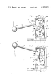
- FIG. 3 is a side elevational view of the apparatus of FIG. 1, in a fully closed position, and with the side of the housing removed to facilitate illustration of the interior components;
- FIG. 4 is a side elevational view similar to FIG. 3, with the apparatus fully opened, and showing an alternate form of link means between the roller members.
- an apparatus for assembling electrical cables, or the like, to an electrical connector which has a cable clamp means for clamping a cable in position with the individual wires thereof terminated with conductive contact means on the connector.
- the connector, cable clamp means and cable will be described in greater detail hereinafter in relation to FIG. 2.
- Apparatus 10 has a base which includes a lower portion 12 and an upstanding housing portion, generally designated 14.
- the upstanding housing includes a pair of side walls 16, a rear wall 18, a top wall 20, and a front wall 22. These walls define a generally hollow structure, and the side, front and rear walls seat over a mounting block 24 which is secured to or integral with lower support portion 12 of the base.
- Side walls 16 are secured to mounting block 24 by a pair of bolts 26. Similar bolts (not shown) extend through rear wall 18 at the lower end thereof to secure the rear wall to mounting block 24.
- Front wall 22 and top wall 20 actually may comprise integral portions of either of the side walls.
- Front and rear bolts 30A and 30B respectively, secure the top of the housing portion and extend through side walls 16.
- front wall 22 extends upwardly only approximately one-half of the height of housing portion 14, so as to define a front opening, generally designated 32, in the front of the housing.
- a pair of upper and lower roller members 34A and 34B, respectively, are mounted within housing portion 14 of the base for rotation about generally parallel, spaced horizontal axes which are defined by shafts 36.
- Shafts 36 are journalled in side walls 16.
- the rollers have opposed notches 38 cut into the peripheries thereof, defining jaws for movement toward and away from a connector to engage cable clamp means on the connector for clamping a cable to provide strain relief therefore.
- the side walls of housing 14 are cut-out, as at 39, to provide access to the mouth area defined between jaws 38 for accepting a connector and cable clamp. It can be seen that with the use of rollers with notches cut in the peripheries thereof, a wide target area is provided for accepting a spread cable clamp prior to crimping.
- An actuator in the form of a lever member 40 is fixed at one end 40A to upper roller 30A so as to extend outwardly therefrom through opening 32 in housing portion 14, in a plane generally perpendicular to the axes of rotation of the rollers defined by shafts 36.
- a knob-like handle 42 is secured to the outer end of lever member 40 to facilitate manual manipulation thereof and effect rotation of roller members 34A, 34B.
- a coil spring 44 is wrapped about a pair of pins 46 secured to the rollers.
- the spring is maintained in tension and, being interconnected between the rollers, biases the rollers in an opening direction away from the cable clamp.
- Direct-drive link means interconnects rollers 34A, 34B for conjoint rotation thereof in opposite directions toward and away from a cable clamp in response to movement of lever member 40.
- link means 48 comprises a slidable plate 50 which extends between the rollers in direct driving relationship therewith.
- Roller 34A has a groove 52 and roller 34B has an opposed, facing groove 54 for slidably receiving plate 50.
- Groove 52 in roller 34A is deeper than groove 34 in roller 34B, and a back-up coil spring 56 is seated within a recess 58 cut into the rear of plate 50 within groove 52.
- Spring 56 biases plate 50 toward and into groove 54 in roller 34. In this manner, plate 50 is free to move longitudinally within groove 52 in roller 34A, while maintaining constant engagement with roller 34B within groove 54 thereof, while the rollers are rotated in unison by lever member 40.
- Stop means is provided in the form of a pair of front and rear pins 60A and 60B, respectively, protruding outwardly from the top periphery of roller 34A.
- the pins are positioned so as to abut against bolt 30A which extends between side walls 16 of housing portion 14, and thereby provide limits of movement of the rollers in either direction of rotation.
- apparatus 10 is designed for assembling electrical cables 62 to an electrical connector, generally designated 64, which has cable clamp means, generally designated 66, for clamping cable 62 in position for termination with conductive contact means (not shown) on the connector.
- the cable normally has an outer covering surrounding a plurality of individual wires or conductors (not shown) which are terminated to the individual contacts which normally are positioned within slots of the connector.
- Cable clamp 66 forms a part of connector 64 and has a pair of outwardly diverging wings 68 which are utilized to clamp onto the outer covering of cable 62 and provide strain relief therefor.
- Rollers 34A, 34B are shown in FIG. 2 in their fully opened positions, with stop pin 60A abutting against the front of bolt 30A. In this open condition, cable clamp 66, with cable 62 disposed between spring wings 68, is easily positionable between jaws 38 of the roller members.
- lever member 40 and rollers 30A, 30B are shown in fully closed positions, with stop pin 60B in abuttment against the rear of bolt 30A.
- jaws 38 are prevented from closing onto the cable clamp beyond a predetermined angle of rotation of the rollers. This angle is determined so as to prevent excessive clamping forces on cable 62 which might damage the individual electrical wires or conductors therein.
- spring 44 is effective to return the lever and rollers to their fully opened condition as shown in FIGS. 1 and 2.
- an alternate form of direct-drive link means is disclosed interconnecting the roller members. More particularly, a flat, flexible leaf spring 70 extends between roller 34A, 34B for drivingly interconnecting the rollers.
- the leaf spring is slidably received within opposed, facing grooves 72 in the roller members. The grooves are of equal depth, and the leaf spring is self contained therewithin.
- the rollers and jaws 38 are shown in open condition for receiving cable clamp 66, and like numerals are applied in FIG. 4 for like components of the apparatus corresponding to FIGS. 1-3.
- a simple direct drive is provided between the rollers and eliminates such driving mechanisms as gears, belts, or the like.
Landscapes
- Engineering & Computer Science (AREA)
- Manufacturing & Machinery (AREA)
- Manufacturing Of Electrical Connectors (AREA)
Abstract
Description
Claims (17)
Priority Applications (1)
| Application Number | Priority Date | Filing Date | Title |
|---|---|---|---|
| US06/167,945 US4373372A (en) | 1980-07-14 | 1980-07-14 | Apparatus for assembling electrical cables to electrical connectors |
Applications Claiming Priority (1)
| Application Number | Priority Date | Filing Date | Title |
|---|---|---|---|
| US06/167,945 US4373372A (en) | 1980-07-14 | 1980-07-14 | Apparatus for assembling electrical cables to electrical connectors |
Publications (1)
| Publication Number | Publication Date |
|---|---|
| US4373372A true US4373372A (en) | 1983-02-15 |
Family
ID=22609471
Family Applications (1)
| Application Number | Title | Priority Date | Filing Date |
|---|---|---|---|
| US06/167,945 Expired - Lifetime US4373372A (en) | 1980-07-14 | 1980-07-14 | Apparatus for assembling electrical cables to electrical connectors |
Country Status (1)
| Country | Link |
|---|---|
| US (1) | US4373372A (en) |
Cited By (1)
| Publication number | Priority date | Publication date | Assignee | Title |
|---|---|---|---|---|
| US10259126B1 (en) * | 2017-10-10 | 2019-04-16 | Verily Life Sciences Llc | Modular cable strain relief device for articulated arm robotic systems |
Citations (4)
| Publication number | Priority date | Publication date | Assignee | Title |
|---|---|---|---|---|
| GB370961A (en) * | 1931-01-13 | 1932-04-13 | Bell Telephone Labor Inc | Tool for joining wires by rolling |
| US2248147A (en) * | 1939-12-21 | 1941-07-08 | American Chain & Cable Co | Dimpling machine |
| US2639754A (en) * | 1945-03-03 | 1953-05-26 | Aircraft Marine Prod Inc | Tool for crimping ferrules |
| US2903929A (en) * | 1958-02-13 | 1959-09-15 | Paul W Mcvey | Ferrule reducer |
-
1980
- 1980-07-14 US US06/167,945 patent/US4373372A/en not_active Expired - Lifetime
Patent Citations (4)
| Publication number | Priority date | Publication date | Assignee | Title |
|---|---|---|---|---|
| GB370961A (en) * | 1931-01-13 | 1932-04-13 | Bell Telephone Labor Inc | Tool for joining wires by rolling |
| US2248147A (en) * | 1939-12-21 | 1941-07-08 | American Chain & Cable Co | Dimpling machine |
| US2639754A (en) * | 1945-03-03 | 1953-05-26 | Aircraft Marine Prod Inc | Tool for crimping ferrules |
| US2903929A (en) * | 1958-02-13 | 1959-09-15 | Paul W Mcvey | Ferrule reducer |
Cited By (1)
| Publication number | Priority date | Publication date | Assignee | Title |
|---|---|---|---|---|
| US10259126B1 (en) * | 2017-10-10 | 2019-04-16 | Verily Life Sciences Llc | Modular cable strain relief device for articulated arm robotic systems |
Similar Documents
| Publication | Publication Date | Title |
|---|---|---|
| US4386461A (en) | Ribbon cable connector tool | |
| US4005518A (en) | Apparatus for connecting conductors in flat cable to terminals in a connector | |
| US4701138A (en) | Solderless electrical connector | |
| US3935637A (en) | Removable wiring device assembly | |
| EP0004283A1 (en) | Tool for applying connectors to flexible cable | |
| EP0048085A1 (en) | Connector latching mechanism | |
| US6872090B2 (en) | Cable terminating apparatus and method | |
| US5402561A (en) | Crimping tool having angularly offset crimping dies | |
| US4227299A (en) | Hand tool for terminal connection of electrical cable to an electrical connector | |
| US3504417A (en) | Locator in a crimping tool for an electrical connector | |
| EP0122286A1 (en) | Communication plug connection tool | |
| US3706121A (en) | Crimping dies for terminating foil conductor in a foil conductor termination and foil locator and holder therefor | |
| US4754636A (en) | Connector locating device for crimping tools | |
| US4373372A (en) | Apparatus for assembling electrical cables to electrical connectors | |
| US4203196A (en) | Wire insertion tool | |
| US4519129A (en) | Mass termination connector tool assembly | |
| US4193187A (en) | Clamp-squeezing apparatus | |
| US5212882A (en) | Tool for connecting conductors to IDC terminals | |
| US4334353A (en) | Apparatus for assembling electrical cables to electrical connectors | |
| US4044451A (en) | Apparatus for inserting wires into terminals in modular type connector | |
| US3845523A (en) | Cable clamp | |
| US4793824A (en) | Wedge slot connector | |
| US4041740A (en) | Hand tool | |
| US4292732A (en) | Applicator for metal strain relief clamp | |
| US3999270A (en) | Wire insertion apparatus |
Legal Events
| Date | Code | Title | Description |
|---|---|---|---|
| STCF | Information on status: patent grant |
Free format text: PATENTED CASE |
|
| AS | Assignment |
Owner name: ALLIED CORPORATION COLUMBIA ROAD AND PARK AVENUE, Free format text: ASSIGNMENT OF ASSIGNORS INTEREST.;ASSIGNOR:BUNKER RAMO CORPORATION A CORP. OF DE;REEL/FRAME:004149/0365 Effective date: 19820922 |
|
| AS | Assignment |
Owner name: CANADIAN IMPERIAL BANK OF COMMERCE, NEW YORK AGENC Free format text: SECURITY INTEREST;ASSIGNOR:AMPHENOL CORPORATION;REEL/FRAME:004879/0030 Effective date: 19870515 |
|
| AS | Assignment |
Owner name: AMPHENOL CORPORATION, LISLE, ILLINOIS A CORP. OF D Free format text: ASSIGNMENT OF ASSIGNORS INTEREST.;ASSIGNOR:ALLIED CORPORATION, A CORP. OF NY;REEL/FRAME:004844/0850 Effective date: 19870602 Owner name: AMPHENOL CORPORATION, A CORP. OF DE, ILLINOIS Free format text: ASSIGNMENT OF ASSIGNORS INTEREST;ASSIGNOR:ALLIED CORPORATION, A CORP. OF NY;REEL/FRAME:004844/0850 Effective date: 19870602 |
|
| AS | Assignment |
Owner name: BANKERS TRUST COMPANY, AS AGENT Free format text: SECURITY INTEREST;ASSIGNOR:AMPHENOL CORPORATION, A CORPORATION OF DE;REEL/FRAME:006035/0283 Effective date: 19911118 |
|
| AS | Assignment |
Owner name: AMPHENOL CORPORATION A CORP. OF DELAWARE Free format text: RELEASED BY SECURED PARTY;ASSIGNOR:CANADIAN IMPERIAL BANK OF COMMERCE;REEL/FRAME:006147/0887 Effective date: 19911114 |
|
| AS | Assignment |
Owner name: AMPHENOL CORPORATION, CONNECTICUT Free format text: RELEASE BY SECURED PARTY;ASSIGNOR:BANKERS TRUST COMPANY;REEL/FRAME:007317/0148 Effective date: 19950104 |