US4372575A - Vehicle strut type suspension with alignment adjustment - Google Patents
Vehicle strut type suspension with alignment adjustment Download PDFInfo
- Publication number
- US4372575A US4372575A US06/232,833 US23283381A US4372575A US 4372575 A US4372575 A US 4372575A US 23283381 A US23283381 A US 23283381A US 4372575 A US4372575 A US 4372575A
- Authority
- US
- United States
- Prior art keywords
- strut
- plate assembly
- slots
- tower portion
- vehicle
- Prior art date
- Legal status (The legal status is an assumption and is not a legal conclusion. Google has not performed a legal analysis and makes no representation as to the accuracy of the status listed.)
- Expired - Fee Related
Links
- 239000000725 suspension Substances 0.000 title claims abstract description 15
- 239000002184 metal Substances 0.000 claims abstract description 11
- 230000003014 reinforcing effect Effects 0.000 claims description 7
- 238000002955 isolation Methods 0.000 claims description 2
- 230000035939 shock Effects 0.000 description 4
- 239000006096 absorbing agent Substances 0.000 description 2
- 230000000712 assembly Effects 0.000 description 2
- 238000000429 assembly Methods 0.000 description 2
- 238000006243 chemical reaction Methods 0.000 description 1
- 230000000295 complement effect Effects 0.000 description 1
- 238000010276 construction Methods 0.000 description 1
- 230000008030 elimination Effects 0.000 description 1
- 238000003379 elimination reaction Methods 0.000 description 1
- 230000014759 maintenance of location Effects 0.000 description 1
- 238000004519 manufacturing process Methods 0.000 description 1
- 239000000463 material Substances 0.000 description 1
- 230000013011 mating Effects 0.000 description 1
- 230000002787 reinforcement Effects 0.000 description 1
- 238000003466 welding Methods 0.000 description 1
Images

Classifications
-
- B—PERFORMING OPERATIONS; TRANSPORTING
- B62—LAND VEHICLES FOR TRAVELLING OTHERWISE THAN ON RAILS
- B62D—MOTOR VEHICLES; TRAILERS
- B62D17/00—Means on vehicles for adjusting camber, castor, or toe-in
-
- B—PERFORMING OPERATIONS; TRANSPORTING
- B60—VEHICLES IN GENERAL
- B60G—VEHICLE SUSPENSION ARRANGEMENTS
- B60G13/00—Resilient suspensions characterised by arrangement, location or type of vibration dampers
- B60G13/001—Arrangements for attachment of dampers
- B60G13/003—Arrangements for attachment of dampers characterised by the mounting on the vehicle body or chassis of the damper unit
-
- B—PERFORMING OPERATIONS; TRANSPORTING
- B60—VEHICLES IN GENERAL
- B60G—VEHICLE SUSPENSION ARRANGEMENTS
- B60G15/00—Resilient suspensions characterised by arrangement, location or type of combined spring and vibration damper, e.g. telescopic type
- B60G15/02—Resilient suspensions characterised by arrangement, location or type of combined spring and vibration damper, e.g. telescopic type having mechanical spring
- B60G15/06—Resilient suspensions characterised by arrangement, location or type of combined spring and vibration damper, e.g. telescopic type having mechanical spring and fluid damper
- B60G15/067—Resilient suspensions characterised by arrangement, location or type of combined spring and vibration damper, e.g. telescopic type having mechanical spring and fluid damper characterised by the mounting on the vehicle body or chassis of the spring and damper unit
- B60G15/068—Resilient suspensions characterised by arrangement, location or type of combined spring and vibration damper, e.g. telescopic type having mechanical spring and fluid damper characterised by the mounting on the vehicle body or chassis of the spring and damper unit specially adapted for MacPherson strut-type suspension
-
- B—PERFORMING OPERATIONS; TRANSPORTING
- B60—VEHICLES IN GENERAL
- B60G—VEHICLE SUSPENSION ARRANGEMENTS
- B60G2200/00—Indexing codes relating to suspension types
- B60G2200/40—Indexing codes relating to the wheels in the suspensions
- B60G2200/46—Indexing codes relating to the wheels in the suspensions camber angle
-
- B—PERFORMING OPERATIONS; TRANSPORTING
- B60—VEHICLES IN GENERAL
- B60G—VEHICLE SUSPENSION ARRANGEMENTS
- B60G2202/00—Indexing codes relating to the type of spring, damper or actuator
- B60G2202/30—Spring/Damper and/or actuator Units
- B60G2202/31—Spring/Damper and/or actuator Units with the spring arranged around the damper, e.g. MacPherson strut
- B60G2202/312—The spring being a wound spring
-
- B—PERFORMING OPERATIONS; TRANSPORTING
- B60—VEHICLES IN GENERAL
- B60G—VEHICLE SUSPENSION ARRANGEMENTS
- B60G2204/00—Indexing codes related to suspensions per se or to auxiliary parts
- B60G2204/10—Mounting of suspension elements
- B60G2204/12—Mounting of springs or dampers
- B60G2204/124—Mounting of coil springs
-
- B—PERFORMING OPERATIONS; TRANSPORTING
- B60—VEHICLES IN GENERAL
- B60G—VEHICLE SUSPENSION ARRANGEMENTS
- B60G2204/00—Indexing codes related to suspensions per se or to auxiliary parts
- B60G2204/10—Mounting of suspension elements
- B60G2204/12—Mounting of springs or dampers
- B60G2204/128—Damper mount on vehicle body or chassis
-
- B—PERFORMING OPERATIONS; TRANSPORTING
- B60—VEHICLES IN GENERAL
- B60G—VEHICLE SUSPENSION ARRANGEMENTS
- B60G2204/00—Indexing codes related to suspensions per se or to auxiliary parts
- B60G2204/40—Auxiliary suspension parts; Adjustment of suspensions
- B60G2204/41—Elastic mounts, e.g. bushings
-
- B—PERFORMING OPERATIONS; TRANSPORTING
- B60—VEHICLES IN GENERAL
- B60G—VEHICLE SUSPENSION ARRANGEMENTS
- B60G2204/00—Indexing codes related to suspensions per se or to auxiliary parts
- B60G2204/40—Auxiliary suspension parts; Adjustment of suspensions
- B60G2204/43—Fittings, brackets or knuckles
-
- B—PERFORMING OPERATIONS; TRANSPORTING
- B60—VEHICLES IN GENERAL
- B60G—VEHICLE SUSPENSION ARRANGEMENTS
- B60G2204/00—Indexing codes related to suspensions per se or to auxiliary parts
- B60G2204/40—Auxiliary suspension parts; Adjustment of suspensions
- B60G2204/44—Centering or positioning means
-
- B—PERFORMING OPERATIONS; TRANSPORTING
- B60—VEHICLES IN GENERAL
- B60G—VEHICLE SUSPENSION ARRANGEMENTS
- B60G2204/00—Indexing codes related to suspensions per se or to auxiliary parts
- B60G2204/61—Adjustable during maintenance
Definitions
- This invention relates to vehicle wheel suspensions of the so-called MacPherson strut type and to provisions in such type suspensions for accomplishing caster and/or camber adjustment of the wheel carried by such suspensions.
- a vertical strut member carries at its lower end the usual wheel knuckle and is there connected with a lateral control arm, the upper end of the strut member being mounted to a high portion of the vehicle superstructure. It is often desirable to provide caster and camber adjustment in this and other types of vehicle suspensions, but complications arise when attempting to incorporate such provisions in the strut type suspension without adding undue structural complexity to the strut structure, particularly where both caster and camber adjustment is desired.
- a desirable expedient to provide for such adjustment is by altering the attitude of the strut axis through relative movement between the upper end of the strut and its attachment location in the vehicle superstructure, as by use of slotted fastener locations.
- the present invention has accomplished a solution to providing the desired adjustment capability in sheet metal superstructure and without sacrifice of strength of the latter. It includes upper strut mounting apparatus wherein caster and/or camber adjustment may be performed through the use of slotted members adjustably affixed to a thin stamped sheet metal tower of the vehicle superstructure by conventional threaded or like fasteners. Such members further serve to stiffen or reinforce the superstructure notwithstanding the slotting. Further, the strut mounting members are adapted to avoid adding any appreciable amount of weight, or of total overall strut height thereby to maintain a low vehicle profile.
- the invention also features a fastener retainer and reinforcing structure which improves vehicle assembly and service operations.
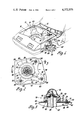
- FIG. 1 is a partially broken away perspective view of a vehicle body including a strut type suspension and adjustable upper mounting apparatus therefor according to the invention.
- FIG. 2 is a fragmentary partially broken away plan view of the upper end mounting apparatus of the invention taken generally along the plane indicated by lines 2--2 of FIG. 1.
- FIG. 3 is a sectional view taken generally along the planes indicated by lines 3--3 of FIG. 2;
- FIG. 4 is an exploded perspective view.
- a vehicle body designated generally as 10 is of so-called integral frame/body construction and features the use of a plurality of stamped and welded relatively lightweight sheet metal super-structure assemblies.
- such superstructure includes a stamped dash panel assembly 12 joined by welding or the like with a motor compartment side panel assembly 14.
- Each such panel assembly comprises a number of individual panels formed of stamped sheet metal, each reinforced by suitable turned flanges, depressions and upsets.
- a rail assembly 16 similarly formed of stamped sheet panels welded together in box-like configuration, extends forwardly on either side of the motor compartment and is welded to the dash panel and motor compartment assemblies 12 and 14.
- this illustrative embodiment incorporates within the side panel assembly 14 a box-like strut mounting tower 18 at a high location. It is again formed of relatively lightweight sheet metal and either integrally formed with the large panel of the panel assembly 14 or separately formed and welded thereto. Such tower includes a flat generally horizontal mounting surface for purposes to be described.
- the front suspension assembly at each side of vehicle body 10 is designated generally as 20 and is of well-known type including a strut member 22 comprised of upper and lower telescopic portions, not shown, incorporating a hydraulic shock absorber.
- a saddle-type knuckle mounting bracket 24 is welded to the lower telescopic portion of the strut member 22, and a forged or like-formed wheel knuckle and spindle member 26 is received between flanges of the bracket 24 and fixed thereto as by bolts.
- Suspension 20 further includes a lower control arm 28 extending laterally from conventional rubber bushed inward pivots, at longitudinally spaced locations on frame rail assembly 16, to a ball joint or like outer connection, not shown, with the knuckle and spindle member 26.
- a disk-type brake and wheel hub assembly designated generally as 30, is mounted in known manner on the knuckle and spindle member 26.
- a coil suspension spring 32 is interposed between an upper surface of the control arm 28 and a reaction mount panel portion of the motor compartment side panel assembly 14.
- the upper telescopic portion of the strut member 22 comprises a shock absorber rod element 34 terminating in a threaded end with nut attached.
- the inner race of a bearing 36 is captured therebetween, such bearing accommodating steering rotation of the strut 22 in known manner.
- a strut mounting upper plate assembly designated generally as 38, is located atop tower 18. It is structured as an inverted dish with a large internal cavity receiving the shock rod 34. A rubber or like sheath 40 covers the latter. Another cover 41 of rubber or the like closes a service access port of the mounting plate assembly 38.
- the mounting plate assembly 38 comprises a centrally apertured lower plate 42 stamped with an annular rib 44 around the central aperture.
- An upper plate 46 shaped complementary in plan view to the lower plate, is likewise stamped with the deep inverted dish or annular crown 48 having an annular flange 50.
- Interposed within crown 48 between such flange 50 and the lower plate 42 is an isolation bushing subassembly 52.
- Such subassembly comprises a rubber or like-material bushing element 54 provided with a bonded central disc-shaped sheet metal retention element 56 to which is affixed as by welds or rivets the outer race of bearing 36.
- the mounting plate assembly 38 features further the provision of fastener locations within the complementarily shaped flanges of the upper and lower plates 42 and 46, specifically by slots 60 with parallel axes and centered on points widely spaced about the axis of shock rod 34.
- Such mounting plate assembly 38 is fabricated in sandwich style as a permanent unit by use of rivets at several locations, indicated at 58, through the mating flanges of the upper and lower plates.
- the horizontal surface of tower 18 is similarly slotted at 62 at locations juxtaposed generally to the slot locations 60 of the mounting plate assembly, and along parallel axes arranged perpendicularly to parallel axes of the slots 60.
- the upper mounting plate assembly 38 is adapted for securement to such surface of the tower 18 through slots 60 and 62, by means of threaded studs or like fasteners.
- a reinforcing member 64 of dimension sufficient to encompass all of the mated slots 60 and 62 thereabove. It is stamped and includes a turned rigidifying flange 66. With such breadth and self-rigidity, it can act as a clampable reinforcement of tower 18. While preferably of "L" shape as shown, it is of course practical to configure this member as a rectangular or like plate which surrounds the strut member 22, but with some sacrifice in ease of assembly as compared to the L-shape.
- Member 64 in addition to its reinforcing function, may serve as a convenient retainer for a series of threaded studs 68 staked thereto. These may be inserted upwardly in a single motion through the juxtaposed slots 60 and 62 of the mounting plate assembly 38 and tower 18. Thus, the upper end of the strut member 22 is readily secured to tower 18 of the vehicle body by tightening over studs 68 and washers 70 of threaded nuts 72 to firmly clamp the tower between the rigid members 38 and 64.
- Slots 60 and 62 accommodate a defined range of adjustment of both caster and camber for the strut member 22 and wheel hub 30 via relative movement between the mounting plate assembly 38, member 64 and tower 18. Such adjustment may proceed individually either in movement of assembly 38 and member 64 within slots 62 in direction forwardly and rearwardly of the vehicle for caster, or movement of assembly 38 inboard and outboard within slots 62 for camber, or simultaneously in both directions. This is accomplished merely by loosening of nuts 72 to permit inclining the axis of the entire strut member 22 to the desired attitude both longitudinally and inboard-outboard of the vehicle superstructure.
- a number of alternative arrangements to that illustrated herein is of course available within the spirit of the invention and could include, for example, locating the mounting plate assembly 38 underneath the tower 18 and applying the reinforcing member 64 to the top surface thereof. Ease of assembly may dictate that in certain situtations it is preferable to reverse the threaded studs and nuts between the assembly 38 and the member 64. It is practical to merely utilize apertures in member 64 and not employ it as a fastener retainer. But generally, the use of such member as a retainer for fastener elements, whether studs or nuts, is of definite advantage in conveniently assembling the strut suspension both during manufacture and field service operations.
Landscapes
- Engineering & Computer Science (AREA)
- Mechanical Engineering (AREA)
- Chemical & Material Sciences (AREA)
- Combustion & Propulsion (AREA)
- Transportation (AREA)
- Body Structure For Vehicles (AREA)
- Vehicle Body Suspensions (AREA)
Abstract
Description
Claims (1)
Priority Applications (1)
| Application Number | Priority Date | Filing Date | Title |
|---|---|---|---|
| US06/232,833 US4372575A (en) | 1981-02-09 | 1981-02-09 | Vehicle strut type suspension with alignment adjustment |
Applications Claiming Priority (1)
| Application Number | Priority Date | Filing Date | Title |
|---|---|---|---|
| US06/232,833 US4372575A (en) | 1981-02-09 | 1981-02-09 | Vehicle strut type suspension with alignment adjustment |
Publications (1)
| Publication Number | Publication Date |
|---|---|
| US4372575A true US4372575A (en) | 1983-02-08 |
Family
ID=22874799
Family Applications (1)
| Application Number | Title | Priority Date | Filing Date |
|---|---|---|---|
| US06/232,833 Expired - Fee Related US4372575A (en) | 1981-02-09 | 1981-02-09 | Vehicle strut type suspension with alignment adjustment |
Country Status (1)
| Country | Link |
|---|---|
| US (1) | US4372575A (en) |
Cited By (35)
| Publication number | Priority date | Publication date | Assignee | Title |
|---|---|---|---|---|
| EP0092066A1 (en) * | 1982-04-21 | 1983-10-26 | FIAT AUTO S.p.A. | Vehicle wheel suspension |
| US4493493A (en) * | 1982-10-18 | 1985-01-15 | General Motors Corporation | Alignment adjustment apparatus for vehicle wheel suspension |
| US4615537A (en) * | 1984-12-21 | 1986-10-07 | Ford Motor Company | Reduced friction automotive suspension strut mounting |
| US4721325A (en) * | 1986-11-19 | 1988-01-26 | General Motors Corporation | Suspension strut with quick take-apart upper mount |
| US4817984A (en) * | 1986-09-10 | 1989-04-04 | Arindol Pty. Limited | Vehicle suspension system |
| US4867473A (en) * | 1988-07-29 | 1989-09-19 | Jordan Robert O | Method for adjusting camber of MacPherson strut |
| US4909642A (en) * | 1988-02-04 | 1990-03-20 | Dr. Ing. H.C.F. Porsche Ag | Shiftable elastic support bearing for vibration dampers for vehicles |
| US4944524A (en) * | 1987-11-18 | 1990-07-31 | Ford Motor Company | Telescoping strut suspension with friction reducing torsional unloading device |
| US4948160A (en) * | 1989-01-17 | 1990-08-14 | Barry David L | Method and apparatus for modifying wheel alignment in strut type suspension |
| US4971348A (en) * | 1986-05-16 | 1990-11-20 | Honda Giken Kogyo Kabushiki Kaisha | Camber control system for motor vehicle |
| US5011201A (en) * | 1987-07-10 | 1991-04-30 | Mazda Motor Corporation | Front structure of vehicle body |
| WO1993000244A1 (en) * | 1991-06-21 | 1993-01-07 | Kevin Joseph Mcintyre | Adjustable mounting for suspension strut |
| AU656009B2 (en) * | 1991-06-21 | 1995-01-19 | Kevin Joseph Mcintyre | Adjustable mounting for suspension strut |
| DE19543798A1 (en) * | 1995-11-24 | 1997-05-28 | Porsche Ag | Device for adjusting a vehicle wheel |
| US6007056A (en) * | 1991-06-11 | 1999-12-28 | Cannondale Corporation | Suspension assembly for a vehicle |
| US6082749A (en) * | 1998-09-23 | 2000-07-04 | Chrysler Corporation | Alignment pin and slot structure for a spring and strut module of an automotive vehicle |
| US6257601B1 (en) * | 1999-08-18 | 2001-07-10 | Northstar Manufacturing Co., Inc. | Mounting plate for adjustably positioning vehicle suspension struts |
| US6328321B1 (en) | 1999-05-24 | 2001-12-11 | Noltec Distribution | Adjustable mounting for suspension strut |
| US6382645B1 (en) | 2000-12-04 | 2002-05-07 | Northstar Manufacturing Co., Inc. | Offset upper strut mount |
| US6485223B1 (en) * | 2001-07-13 | 2002-11-26 | Maximum Motorsports | Caster-camber plate assembly |
| WO2004012979A1 (en) * | 2002-07-25 | 2004-02-12 | Daimlerchrysler Ag | Fixing arrangement for a spring and/or damping element to a hollow support on a motor vehicle chassis |
| US20050073120A1 (en) * | 2001-08-20 | 2005-04-07 | William Mathis | Front suspension tuning apparatus |
| US20050115785A1 (en) * | 2003-10-30 | 2005-06-02 | Sean Thomas | Upper strut mount |
| US20050218618A1 (en) * | 2004-04-02 | 2005-10-06 | Carlson Andrew D | Front suspension tuning apparatus for vehicle with struts |
| US20060125164A1 (en) * | 2002-10-23 | 2006-06-15 | Meritor Suspension Systems Company, Inc. | Resilient bushing mount for a vehicle suspension |
| US20060125198A1 (en) * | 2004-12-15 | 2006-06-15 | Choi Sang-Jun | Wheel alignment and vehicle height adjusting apparatus |
| US20070164527A1 (en) * | 2004-11-26 | 2007-07-19 | Steeda Autosports, Inc. | Front suspension tuning apparatus |
| US20080224369A1 (en) * | 2005-10-13 | 2008-09-18 | Renault S.A.S. | Sheathing for a Suspension Spring |
| US20080303233A1 (en) * | 2007-06-08 | 2008-12-11 | Luka Dugandzic | Caster-camber plate assemblies |
| US7513514B1 (en) | 2004-10-29 | 2009-04-07 | Niwot Corporation | Adjustable ball joint connection assembly |
| US20110203889A1 (en) * | 2010-02-22 | 2011-08-25 | Tae Woong Eom | Assembly and disassembly-type damping force adjustable shock absorber |
| WO2011120682A1 (en) * | 2010-04-03 | 2011-10-06 | Volkswagen Aktiengesellschaft | Modular body structure of a motor vehicle |
| US8820759B1 (en) * | 2013-10-01 | 2014-09-02 | Brian Croutcher | Plates allowing adjustment of caster and camber |
| US20150091268A1 (en) * | 2013-10-01 | 2015-04-02 | Brian Croutcher | Plates Allowing Adjustment of Caster and Camber |
| US20160031485A1 (en) * | 2014-08-01 | 2016-02-04 | Mazda Motor Corporation | Front vehicle-body structure of vehicle |
Citations (5)
| Publication number | Priority date | Publication date | Assignee | Title |
|---|---|---|---|---|
| US2065071A (en) * | 1934-07-12 | 1936-12-22 | Chrysler Corp | Vehicle wheel suspension |
| US2299926A (en) * | 1940-06-13 | 1942-10-27 | Nash Kelvinator Corp | Automotive suspension |
| US4175771A (en) * | 1978-07-27 | 1979-11-27 | General Motors Corporation | Resilient mounting means for MacPherson strut |
| US4200307A (en) * | 1977-10-08 | 1980-04-29 | Volkswagenwerk Aktiengesellschaft | Mount for supporting a suspension strut assembly on a vehicle body |
| US4213631A (en) * | 1978-06-22 | 1980-07-22 | Wilkerson Edward D | Vehicle wheel alignment adjustment device |
-
1981
- 1981-02-09 US US06/232,833 patent/US4372575A/en not_active Expired - Fee Related
Patent Citations (5)
| Publication number | Priority date | Publication date | Assignee | Title |
|---|---|---|---|---|
| US2065071A (en) * | 1934-07-12 | 1936-12-22 | Chrysler Corp | Vehicle wheel suspension |
| US2299926A (en) * | 1940-06-13 | 1942-10-27 | Nash Kelvinator Corp | Automotive suspension |
| US4200307A (en) * | 1977-10-08 | 1980-04-29 | Volkswagenwerk Aktiengesellschaft | Mount for supporting a suspension strut assembly on a vehicle body |
| US4213631A (en) * | 1978-06-22 | 1980-07-22 | Wilkerson Edward D | Vehicle wheel alignment adjustment device |
| US4175771A (en) * | 1978-07-27 | 1979-11-27 | General Motors Corporation | Resilient mounting means for MacPherson strut |
Cited By (49)
| Publication number | Priority date | Publication date | Assignee | Title |
|---|---|---|---|---|
| EP0092066A1 (en) * | 1982-04-21 | 1983-10-26 | FIAT AUTO S.p.A. | Vehicle wheel suspension |
| US4493493A (en) * | 1982-10-18 | 1985-01-15 | General Motors Corporation | Alignment adjustment apparatus for vehicle wheel suspension |
| US4615537A (en) * | 1984-12-21 | 1986-10-07 | Ford Motor Company | Reduced friction automotive suspension strut mounting |
| US4971348A (en) * | 1986-05-16 | 1990-11-20 | Honda Giken Kogyo Kabushiki Kaisha | Camber control system for motor vehicle |
| US5094472A (en) * | 1986-05-16 | 1992-03-10 | Honda Giken Kogyo Kabushiki Kaisha | Camber control system for motor vehicle |
| US4817984A (en) * | 1986-09-10 | 1989-04-04 | Arindol Pty. Limited | Vehicle suspension system |
| US4721325A (en) * | 1986-11-19 | 1988-01-26 | General Motors Corporation | Suspension strut with quick take-apart upper mount |
| US5011201A (en) * | 1987-07-10 | 1991-04-30 | Mazda Motor Corporation | Front structure of vehicle body |
| US4944524A (en) * | 1987-11-18 | 1990-07-31 | Ford Motor Company | Telescoping strut suspension with friction reducing torsional unloading device |
| US4909642A (en) * | 1988-02-04 | 1990-03-20 | Dr. Ing. H.C.F. Porsche Ag | Shiftable elastic support bearing for vibration dampers for vehicles |
| US4867473A (en) * | 1988-07-29 | 1989-09-19 | Jordan Robert O | Method for adjusting camber of MacPherson strut |
| US4948160A (en) * | 1989-01-17 | 1990-08-14 | Barry David L | Method and apparatus for modifying wheel alignment in strut type suspension |
| US6007056A (en) * | 1991-06-11 | 1999-12-28 | Cannondale Corporation | Suspension assembly for a vehicle |
| US6155541A (en) * | 1991-06-11 | 2000-12-05 | Cannondale Corporation | Suspension assembly for a vehicle |
| WO1993000244A1 (en) * | 1991-06-21 | 1993-01-07 | Kevin Joseph Mcintyre | Adjustable mounting for suspension strut |
| US5484161A (en) * | 1991-06-21 | 1996-01-16 | Mcintyre; Kevin J. | Adjustable mounting for suspension strut |
| AU656009B2 (en) * | 1991-06-21 | 1995-01-19 | Kevin Joseph Mcintyre | Adjustable mounting for suspension strut |
| DE19543798A1 (en) * | 1995-11-24 | 1997-05-28 | Porsche Ag | Device for adjusting a vehicle wheel |
| EP0775602A1 (en) * | 1995-11-24 | 1997-05-28 | Dr.Ing.h.c. F. Porsche Aktiengesellschaft | Device to adjust the wheeel of a vehicle |
| US6082749A (en) * | 1998-09-23 | 2000-07-04 | Chrysler Corporation | Alignment pin and slot structure for a spring and strut module of an automotive vehicle |
| US6328321B1 (en) | 1999-05-24 | 2001-12-11 | Noltec Distribution | Adjustable mounting for suspension strut |
| US6257601B1 (en) * | 1999-08-18 | 2001-07-10 | Northstar Manufacturing Co., Inc. | Mounting plate for adjustably positioning vehicle suspension struts |
| US6382645B1 (en) | 2000-12-04 | 2002-05-07 | Northstar Manufacturing Co., Inc. | Offset upper strut mount |
| US6485223B1 (en) * | 2001-07-13 | 2002-11-26 | Maximum Motorsports | Caster-camber plate assembly |
| US7163215B2 (en) | 2001-08-20 | 2007-01-16 | Steeda Autosports, Inc. | Front suspension tuning apparatus |
| US20050073120A1 (en) * | 2001-08-20 | 2005-04-07 | William Mathis | Front suspension tuning apparatus |
| WO2004012979A1 (en) * | 2002-07-25 | 2004-02-12 | Daimlerchrysler Ag | Fixing arrangement for a spring and/or damping element to a hollow support on a motor vehicle chassis |
| US20060118373A1 (en) * | 2002-07-25 | 2006-06-08 | Olivier Birkwald | Fixing arrangemenrt for a spring and/or damping element to a hollow support on a motor vehicle chassis |
| US20060125164A1 (en) * | 2002-10-23 | 2006-06-15 | Meritor Suspension Systems Company, Inc. | Resilient bushing mount for a vehicle suspension |
| US7448478B2 (en) | 2003-10-30 | 2008-11-11 | Sean Thomas | Upper strut mount |
| US20050115785A1 (en) * | 2003-10-30 | 2005-06-02 | Sean Thomas | Upper strut mount |
| US20050218618A1 (en) * | 2004-04-02 | 2005-10-06 | Carlson Andrew D | Front suspension tuning apparatus for vehicle with struts |
| US7144021B2 (en) | 2004-04-02 | 2006-12-05 | Steeda Autosports, Inc. | Front suspension tuning apparatus for vehicle with struts |
| US7513514B1 (en) | 2004-10-29 | 2009-04-07 | Niwot Corporation | Adjustable ball joint connection assembly |
| US20070164527A1 (en) * | 2004-11-26 | 2007-07-19 | Steeda Autosports, Inc. | Front suspension tuning apparatus |
| US20060125198A1 (en) * | 2004-12-15 | 2006-06-15 | Choi Sang-Jun | Wheel alignment and vehicle height adjusting apparatus |
| US7527275B2 (en) * | 2004-12-15 | 2009-05-05 | Hyundai Motor Company | Wheel alignment and vehicle height adjusting apparatus |
| US20080224369A1 (en) * | 2005-10-13 | 2008-09-18 | Renault S.A.S. | Sheathing for a Suspension Spring |
| US20080303233A1 (en) * | 2007-06-08 | 2008-12-11 | Luka Dugandzic | Caster-camber plate assemblies |
| US7607668B2 (en) | 2007-06-08 | 2009-10-27 | Maximum Motorsports | Caster-camber plate assemblies |
| US20110203889A1 (en) * | 2010-02-22 | 2011-08-25 | Tae Woong Eom | Assembly and disassembly-type damping force adjustable shock absorber |
| WO2011120682A1 (en) * | 2010-04-03 | 2011-10-06 | Volkswagen Aktiengesellschaft | Modular body structure of a motor vehicle |
| CN102917943A (en) * | 2010-04-03 | 2013-02-06 | 大众汽车有限公司 | Modular body structure of a motor vehicle |
| CN102917943B (en) * | 2010-04-03 | 2016-08-17 | 大众汽车有限公司 | The modular cart body structure of automobile |
| US8820759B1 (en) * | 2013-10-01 | 2014-09-02 | Brian Croutcher | Plates allowing adjustment of caster and camber |
| US20150091268A1 (en) * | 2013-10-01 | 2015-04-02 | Brian Croutcher | Plates Allowing Adjustment of Caster and Camber |
| US9073577B2 (en) * | 2013-10-01 | 2015-07-07 | Brian Croutcher | Plates allowing adjustment of caster and camber |
| US20160031485A1 (en) * | 2014-08-01 | 2016-02-04 | Mazda Motor Corporation | Front vehicle-body structure of vehicle |
| US9446797B2 (en) * | 2014-08-01 | 2016-09-20 | Mazda Motor Corporation | Front vehicle-body structure of vehicle |
Similar Documents
| Publication | Publication Date | Title |
|---|---|---|
| US4372575A (en) | Vehicle strut type suspension with alignment adjustment | |
| US4159125A (en) | Uncoupled strut suspension system | |
| JP2600978B2 (en) | Suspension upper link support structure | |
| US4046415A (en) | Body mount system for a motor vehicle | |
| US4418938A (en) | Vehicle strut suspension with camber adjustment | |
| JP2618353B2 (en) | Rack type steering device support device | |
| US5641180A (en) | Vehicle subframe assembly | |
| US6966568B2 (en) | Multi-function bracket for an air suspension | |
| US5344187A (en) | Spring strut mounting assembly of a vehicle body | |
| JP2712815B2 (en) | Subframe mounting structure | |
| US4097057A (en) | Independent suspension system | |
| US2997122A (en) | Vehicle body | |
| GB2111922A (en) | Vehicle suspension system | |
| US4087103A (en) | Independent suspension system | |
| US2696388A (en) | Vehicle body brace | |
| EP1288029B1 (en) | Integrated axle clamp and spring seat device for vehicle suspensions | |
| CA1329229C (en) | Unified frame/body assembly for vehicle | |
| US3223433A (en) | Vehicle suspension construction | |
| US4453738A (en) | Mounting structure for upper control arms in a four link suspension system | |
| JP2565162Y2 (en) | Suspension support tower reinforcement structure | |
| JP2005067432A (en) | Spare tire mounting structure for vehicle | |
| JPH07276949A (en) | Shock absorber fitting structure | |
| JPS6144885Y2 (en) | ||
| US8480105B2 (en) | Vehicle axle with receiver for towing | |
| JPH0529983Y2 (en) |
Legal Events
| Date | Code | Title | Description |
|---|---|---|---|
| AS | Assignment |
Owner name: GENERAL MOTORS CORPORATION, DETROIT, MICH. A CORP. Free format text: ASSIGNMENT OF ASSIGNORS INTEREST.;ASSIGNOR:HYMA MARVIN J.;REEL/FRAME:003866/0639 Effective date: 19810126 |
|
| MAFP | Maintenance fee payment |
Free format text: PAYMENT OF MAINTENANCE FEE, 4TH YEAR, PL 96-517 (ORIGINAL EVENT CODE: M170); ENTITY STATUS OF PATENT OWNER: LARGE ENTITY Year of fee payment: 4 |
|
| MAFP | Maintenance fee payment |
Free format text: PAYMENT OF MAINTENANCE FEE, 8TH YEAR, PL 96-517 (ORIGINAL EVENT CODE: M171); ENTITY STATUS OF PATENT OWNER: LARGE ENTITY Year of fee payment: 8 |
|
| FEPP | Fee payment procedure |
Free format text: PAYOR NUMBER ASSIGNED (ORIGINAL EVENT CODE: ASPN); ENTITY STATUS OF PATENT OWNER: LARGE ENTITY |
|
| FEPP | Fee payment procedure |
Free format text: MAINTENANCE FEE REMINDER MAILED (ORIGINAL EVENT CODE: REM.); ENTITY STATUS OF PATENT OWNER: LARGE ENTITY |
|
| LAPS | Lapse for failure to pay maintenance fees | ||
| FP | Lapsed due to failure to pay maintenance fee |
Effective date: 19950208 |
|
| STCH | Information on status: patent discontinuation |
Free format text: PATENT EXPIRED DUE TO NONPAYMENT OF MAINTENANCE FEES UNDER 37 CFR 1.362 |