US4372222A - Screw and floating drive nut assembly - Google Patents
Screw and floating drive nut assembly Download PDFInfo
- Publication number
- US4372222A US4372222A US06/194,459 US19445980A US4372222A US 4372222 A US4372222 A US 4372222A US 19445980 A US19445980 A US 19445980A US 4372222 A US4372222 A US 4372222A
- Authority
- US
- United States
- Prior art keywords
- bracket
- screw
- nut
- ball nut
- arm
- Prior art date
- Legal status (The legal status is an assumption and is not a legal conclusion. Google has not performed a legal analysis and makes no representation as to the accuracy of the status listed.)
- Expired - Lifetime
Links
Images

Classifications
-
- F—MECHANICAL ENGINEERING; LIGHTING; HEATING; WEAPONS; BLASTING
- F16—ENGINEERING ELEMENTS AND UNITS; GENERAL MEASURES FOR PRODUCING AND MAINTAINING EFFECTIVE FUNCTIONING OF MACHINES OR INSTALLATIONS; THERMAL INSULATION IN GENERAL
- F16H—GEARING
- F16H25/00—Gearings comprising primarily only cams, cam-followers and screw-and-nut mechanisms
- F16H25/18—Gearings comprising primarily only cams, cam-followers and screw-and-nut mechanisms for conveying or interconverting oscillating or reciprocating motions
- F16H25/20—Screw mechanisms
- F16H25/24—Elements essential to such mechanisms, e.g. screws, nuts
-
- B—PERFORMING OPERATIONS; TRANSPORTING
- B23—MACHINE TOOLS; METAL-WORKING NOT OTHERWISE PROVIDED FOR
- B23Q—DETAILS, COMPONENTS, OR ACCESSORIES FOR MACHINE TOOLS, e.g. ARRANGEMENTS FOR COPYING OR CONTROLLING; MACHINE TOOLS IN GENERAL CHARACTERISED BY THE CONSTRUCTION OF PARTICULAR DETAILS OR COMPONENTS; COMBINATIONS OR ASSOCIATIONS OF METAL-WORKING MACHINES, NOT DIRECTED TO A PARTICULAR RESULT
- B23Q5/00—Driving or feeding mechanisms; Control arrangements therefor
- B23Q5/22—Feeding members carrying tools or work
- B23Q5/34—Feeding other members supporting tools or work, e.g. saddles, tool-slides, through mechanical transmission
- B23Q5/38—Feeding other members supporting tools or work, e.g. saddles, tool-slides, through mechanical transmission feeding continuously
- B23Q5/40—Feeding other members supporting tools or work, e.g. saddles, tool-slides, through mechanical transmission feeding continuously by feed shaft, e.g. lead screw
- B23Q5/408—Nut bearings therefor
-
- F—MECHANICAL ENGINEERING; LIGHTING; HEATING; WEAPONS; BLASTING
- F16—ENGINEERING ELEMENTS AND UNITS; GENERAL MEASURES FOR PRODUCING AND MAINTAINING EFFECTIVE FUNCTIONING OF MACHINES OR INSTALLATIONS; THERMAL INSULATION IN GENERAL
- F16H—GEARING
- F16H25/00—Gearings comprising primarily only cams, cam-followers and screw-and-nut mechanisms
- F16H25/18—Gearings comprising primarily only cams, cam-followers and screw-and-nut mechanisms for conveying or interconverting oscillating or reciprocating motions
- F16H25/20—Screw mechanisms
- F16H25/24—Elements essential to such mechanisms, e.g. screws, nuts
- F16H2025/2445—Supports or other means for compensating misalignment or offset between screw and nut
-
- Y—GENERAL TAGGING OF NEW TECHNOLOGICAL DEVELOPMENTS; GENERAL TAGGING OF CROSS-SECTIONAL TECHNOLOGIES SPANNING OVER SEVERAL SECTIONS OF THE IPC; TECHNICAL SUBJECTS COVERED BY FORMER USPC CROSS-REFERENCE ART COLLECTIONS [XRACs] AND DIGESTS
- Y10—TECHNICAL SUBJECTS COVERED BY FORMER USPC
- Y10T—TECHNICAL SUBJECTS COVERED BY FORMER US CLASSIFICATION
- Y10T74/00—Machine element or mechanism
- Y10T74/18—Mechanical movements
- Y10T74/18568—Reciprocating or oscillating to or from alternating rotary
- Y10T74/18576—Reciprocating or oscillating to or from alternating rotary including screw and nut
- Y10T74/1868—Deflection related
Definitions
- This invention relates to precision screw assemblies which are employed to position work tables or the like.
- the invention provides a precision screw assembly incorporating a floating nut adapted to accommodate minor inconformities in the screw and deviations in axial table motion.
- the nut is connected to at least one rod which extends from a bracket attached to the table whereby the nut can move vertically or sidewise. Any twisting or rotation of the nut about its axis is prevented by an arm attached to a side of the nut having its opposite end attached to another bracket on the table.
- the manner of attachment to the second mentioned bracket is such that sidewise and vertical nut movements are untrammelled.
- a precision screw assembly according to the invention is advantageous because it does not mandate precise dimensions, perpendicularities and parallelisms. Any floating of the nut in an assembly of the invention will affect the linear position thereof in a minimal and insignificant way.
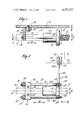
- FIG. 1 is a side elevational view of a precision screw assembly of the invention.
- FIG. 2 is a top plan view of the precision screw assembly of FIG. 1, taken substantially along the line 2--2 of FIG. 1.
- FIG. 3 is a rear elevational view of the precision screw assembly, taken substantially along the line 3--3 of FIG. 2.
- FIG. 1 a precision screw assembly according to the invention.
- the depicted screw assembly is adapted to drive a table 10 (FIGS. 1 and 3) forwardly and rearwardly in the Z directions indicated by the double-headed arrow.
- the table which may be guided by suitable ways (not shown), could be one of the tables of a machine tool, such as a machining center, a chucker or an electrical discharge machine.
- the precision screw assembly includes the usual screw 12 which is in threaded engagement with a conventional ball nut 14 which includes a flange 16. Movements of the ball nut 14, produced by screw rotation, are preferably transmitted to the table 10 by means of a pair of rods 18 and 20.
- the rods 18 and 20 project through bores 16a and 16b in opposite sides of the flange 16 and extend forwardly therefrom parallel to the ball nut 14 and screw 12.
- the forward ends of the rods 18 and 20 are threaded and are respectively secured to the depending legs 22 and 24 of an L-shaped first bracket 26 by nuts 28 and 30.
- the upper or horizontal leg 32 of the bracket 26 is attached to the underside of the table 10 by bolts 34 and 36. As best seen in FIGS. 2 and 3, the legs 22 and 24 straddle the screw as do the rods 18 and 20.
- a Torque arm 38 is provided to prevent the nut 14 from rotating about its axis in either a clockwise or counterclockwise sense.
- the torque arm 38 is preferably constituted by an arm 40 with an annular disc shaped based 42 and a rounded extremity 44.
- the screw is received within the centrally disposed opening 42a in the base 42; and the right threaded ends of the rods 18 and 20 are received in holes 42b and 42c in the base which are respectively aligned with the bores 16a and 16b in the flange 16.
- Nuts 46 and 48 on the respective rear threaded ends of the rods 18 and 20 serve to connect the base 42 to flange 16 such that the forward face of the base 42 abuts the rear face of the flange 16.
- the nuts 46 and 48 also function to secure the ball nut 14 to the rods 18 and 20.
- the ball nut 14, rods 18 and 20 and torque arm 38 move forwardly and rearwardly in unison and define an integral structure.
- the rounded extremity 44 of the horizontally extending torque arm 38 is anchored within a second slot 50 of a bracket 52, the bracket 52 being mounted upon the underside of the table 10 by a bolt 54 and constituting a part thereof.
- the slot 50 is vertically dimensioned whereby a sliding fit is occasioned between the rounded extremity and the upper and lower walls 50a and 50b of the slot.
- the vertical wall 50c of the slot is laterally spaced from the rounded extremity a distance sufficient to insure that no contact will be engendered therebetween. It will be noted that the depicted mounting of the rounded extremity 44 in the slot 50 permits sidewise or axial movement in the X directions of the torque arm 38 and also allows for pivoting of the torque arm about an axis B (FIGS.
- the rods are 6 inches long, have a modulus of elasticity of 30 ⁇ 10 6 and a diameter of 0.375 inches, the change in the linear distance between the bracket 26 and the ball nut is only 0.000075 inches. Furthermore, the force engendered is only about 25 lbs. Forces may easily be computed utilizing a convential cantilever beam analysis. If desired, universal connections may be provided at the forward, rear or both ends of the rods to eliminate any forces caused by floating of the nut.
Landscapes
- Engineering & Computer Science (AREA)
- Mechanical Engineering (AREA)
- General Engineering & Computer Science (AREA)
- Transmission Devices (AREA)
Abstract
A precision drive assembly for the table (b 10) of a machine tool incorporates a screw (12) and floating ball nut (14). The nut is supported by a pair of rods (18,20) which, in turn, are connected to a bracket (26) mounted on the table. The nut is prevented from rotating about its axis by a torque arm (38) extending from the side of the nut and anchored to a bracket (52) attached to the table. Because of this arrangement the nut may move sideways or vertically without substantially altering its linear position.
Description
This invention relates to precision screw assemblies which are employed to position work tables or the like.
Conventional precision screw assemblies mandate accurate alignment of the nut and screw axes throughout the range of movement. The tables or other objects driven by the screw assembly must also be mounted so as to be accurately guided in their axial or linear motions. Also, deviations in the axis of the screw must be minute.
The invention provides a precision screw assembly incorporating a floating nut adapted to accommodate minor inconformities in the screw and deviations in axial table motion.
Succinctly stated, the nut is connected to at least one rod which extends from a bracket attached to the table whereby the nut can move vertically or sidewise. Any twisting or rotation of the nut about its axis is prevented by an arm attached to a side of the nut having its opposite end attached to another bracket on the table. The manner of attachment to the second mentioned bracket is such that sidewise and vertical nut movements are untrammelled.
A precision screw assembly according to the invention is advantageous because it does not mandate precise dimensions, perpendicularities and parallelisms. Any floating of the nut in an assembly of the invention will affect the linear position thereof in a minimal and insignificant way.
Accordingly, it is a primary object of the invention to provide a precision screw assembly having a floating nut which permits wider tolerances.
This and other objects and advantages of the invention will become more readily apparent from the following detailed description, when taken in conjunction with the accompanying drawings, in which:
FIG. 1 is a side elevational view of a precision screw assembly of the invention.
FIG. 2 is a top plan view of the precision screw assembly of FIG. 1, taken substantially along the line 2--2 of FIG. 1.
FIG. 3 is a rear elevational view of the precision screw assembly, taken substantially along the line 3--3 of FIG. 2.
Referring to the drawings, there is shown a precision screw assembly according to the invention. The depicted screw assembly is adapted to drive a table 10 (FIGS. 1 and 3) forwardly and rearwardly in the Z directions indicated by the double-headed arrow. The table, which may be guided by suitable ways (not shown), could be one of the tables of a machine tool, such as a machining center, a chucker or an electrical discharge machine.
The precision screw assembly includes the usual screw 12 which is in threaded engagement with a conventional ball nut 14 which includes a flange 16. Movements of the ball nut 14, produced by screw rotation, are preferably transmitted to the table 10 by means of a pair of rods 18 and 20. The rods 18 and 20 project through bores 16a and 16b in opposite sides of the flange 16 and extend forwardly therefrom parallel to the ball nut 14 and screw 12. The forward ends of the rods 18 and 20 are threaded and are respectively secured to the depending legs 22 and 24 of an L-shaped first bracket 26 by nuts 28 and 30. The upper or horizontal leg 32 of the bracket 26 is attached to the underside of the table 10 by bolts 34 and 36. As best seen in FIGS. 2 and 3, the legs 22 and 24 straddle the screw as do the rods 18 and 20.
A Torque arm 38 is provided to prevent the nut 14 from rotating about its axis in either a clockwise or counterclockwise sense. Essentially the torque arm 38 is preferably constituted by an arm 40 with an annular disc shaped based 42 and a rounded extremity 44. The screw is received within the centrally disposed opening 42a in the base 42; and the right threaded ends of the rods 18 and 20 are received in holes 42b and 42c in the base which are respectively aligned with the bores 16a and 16b in the flange 16. Nuts 46 and 48 on the respective rear threaded ends of the rods 18 and 20 serve to connect the base 42 to flange 16 such that the forward face of the base 42 abuts the rear face of the flange 16. The nuts 46 and 48, of course, also function to secure the ball nut 14 to the rods 18 and 20. Hence, it will be appreciated that the ball nut 14, rods 18 and 20 and torque arm 38 move forwardly and rearwardly in unison and define an integral structure.
The rounded extremity 44 of the horizontally extending torque arm 38 is anchored within a second slot 50 of a bracket 52, the bracket 52 being mounted upon the underside of the table 10 by a bolt 54 and constituting a part thereof. The slot 50 is vertically dimensioned whereby a sliding fit is occasioned between the rounded extremity and the upper and lower walls 50a and 50b of the slot. The vertical wall 50c of the slot is laterally spaced from the rounded extremity a distance sufficient to insure that no contact will be engendered therebetween. It will be noted that the depicted mounting of the rounded extremity 44 in the slot 50 permits sidewise or axial movement in the X directions of the torque arm 38 and also allows for pivoting of the torque arm about an axis B (FIGS. 2 and 3) passing through the rounded extremity 44. Pivoting of the Torque arm about the axis B will, of course, permit vertical movement of the ball nut 14 in the Y directions. It should, however, be evident that the torque arm 44 will positively prevent any rotation of the ball nut 14 about its axis A because of the engagement between the walls 50a and 50b and the rounded extremity 44. Hence, the illustrated mounting permits the ball nut 14 to float sidewise and vertically in a generally vertical plane with consequential flexing of the rods 18 and 20.
Floating of the nut 14 in the directions indicated by the arrows X and Y, (as could be beget, for example, by major deviations in the screw axis) will cause flexure of the rods 18 and 20. However, the axial or linear position of the ball nut 14 with respect to the mounting bracket 26 will remain substantially unaffected. Moreover proper design of the rods 18 and 20 will result in only minimal forces being exerted upon the screw 12 by the ball nut 14. For example, assume that the nut is deflected such that its axis A is 0.03 inches from where it would normally be if the rods were unflexed. If the rods are 6 inches long, have a modulus of elasticity of 30×106 and a diameter of 0.375 inches, the change in the linear distance between the bracket 26 and the ball nut is only 0.000075 inches. Furthermore, the force engendered is only about 25 lbs. Forces may easily be computed utilizing a convential cantilever beam analysis. If desired, universal connections may be provided at the forward, rear or both ends of the rods to eliminate any forces caused by floating of the nut.
Obviously, many modifications and variations are possible in light of the above teachings without departing from the scope or spirit of the invention as defined in the appended claims:
Claims (4)
1. In a precision screw assembly adapted to position table of the type having a screw and a ball nut in threaded engagement with the screw, the improvement comprising:
a rod connected to and extending from the ball nut in parallel relationship to the screw;
a first bracket mounted on the table and fixedly connected to the rod such that motion of the ball nut is transmitted to the table;
an arm connected to and radially extending from the nut;
a second bracket mounted on the table; and
the arm being anchored to the second bracket for pivoting movement with respect to the bracket about an axis generally parallel to the axis of the screw and for axial movement with respect to the second mentioned bracket such that the nut is prevented from rotating about its axis but is free to move sidewise and vertically.
2. The improvement of claim 1, wherein the second bracket has a slot therein and wherein the arm has a rounded extremity received within the slot to thereby anchor the arm to the second bracket such that the arm may move axially and pivot about the rounded extremity.
3. The improvement of claim 2, further including:
another rod connected to and extending from the ball nut in parallel relationship to the screw, and fixedly connected to the first bracket.
4. The improvement of claim 3, wherein the ball nut comprises a flange and wherein the rods are respectively connected to opposite sides of the flange.
Priority Applications (1)
| Application Number | Priority Date | Filing Date | Title |
|---|---|---|---|
| US06/194,459 US4372222A (en) | 1980-10-06 | 1980-10-06 | Screw and floating drive nut assembly |
Applications Claiming Priority (1)
| Application Number | Priority Date | Filing Date | Title |
|---|---|---|---|
| US06/194,459 US4372222A (en) | 1980-10-06 | 1980-10-06 | Screw and floating drive nut assembly |
Publications (1)
| Publication Number | Publication Date |
|---|---|
| US4372222A true US4372222A (en) | 1983-02-08 |
Family
ID=22717677
Family Applications (1)
| Application Number | Title | Priority Date | Filing Date |
|---|---|---|---|
| US06/194,459 Expired - Lifetime US4372222A (en) | 1980-10-06 | 1980-10-06 | Screw and floating drive nut assembly |
Country Status (1)
| Country | Link |
|---|---|
| US (1) | US4372222A (en) |
Cited By (8)
| Publication number | Priority date | Publication date | Assignee | Title |
|---|---|---|---|---|
| US4597303A (en) * | 1983-12-05 | 1986-07-01 | Mitutoyo Mfg. Co., Ltd. | Drivably connecting construction in measuring instrument |
| US4779473A (en) * | 1987-06-01 | 1988-10-25 | Ncr Corporation | Gimbal apparatus for translating rotational motion to accurate linear motion |
| US5292211A (en) * | 1992-03-27 | 1994-03-08 | Nippon Thompson Co., Ltd. | Drive apparatus and XY drive apparatus on which it is equipped |
| US5329825A (en) * | 1992-11-25 | 1994-07-19 | Eastman Kodak Company | Precision moving stage |
| US5392662A (en) * | 1993-09-20 | 1995-02-28 | Eastman Kodak Company | Leadscrew coupler |
| US20060156838A1 (en) * | 2005-01-05 | 2006-07-20 | Las Navas Garcia Jose M | Precision table |
| EP1804483A1 (en) * | 2005-12-29 | 2007-07-04 | Agfa-Gevaert HealthCare GmbH | Driving device for optical scanner |
| US20140298933A1 (en) * | 2013-04-05 | 2014-10-09 | Parker-Hannifin Corporation | Anti-rotate cylinder apparatus |
Citations (6)
| Publication number | Priority date | Publication date | Assignee | Title |
|---|---|---|---|---|
| US2571552A (en) * | 1946-08-24 | 1951-10-16 | Joseph J Mascuch | Electrode feeding mechanism |
| US3347116A (en) * | 1965-02-23 | 1967-10-17 | Pratt & Whitney Inc | Automatic measuring lead screw compensator |
| US3495519A (en) * | 1967-02-01 | 1970-02-17 | Microform Data Systems | Xy table |
| US4193317A (en) * | 1977-02-09 | 1980-03-18 | Fuji Photo Film Co., Ltd. | Fine position control device |
| US4274294A (en) * | 1979-07-02 | 1981-06-23 | Rca Corporation | Apparatus for converting rotary motion to linear motion |
| US4302981A (en) * | 1979-03-20 | 1981-12-01 | Crosfield Electronics Limited | Longitudinal drive mechanisms |
-
1980
- 1980-10-06 US US06/194,459 patent/US4372222A/en not_active Expired - Lifetime
Patent Citations (6)
| Publication number | Priority date | Publication date | Assignee | Title |
|---|---|---|---|---|
| US2571552A (en) * | 1946-08-24 | 1951-10-16 | Joseph J Mascuch | Electrode feeding mechanism |
| US3347116A (en) * | 1965-02-23 | 1967-10-17 | Pratt & Whitney Inc | Automatic measuring lead screw compensator |
| US3495519A (en) * | 1967-02-01 | 1970-02-17 | Microform Data Systems | Xy table |
| US4193317A (en) * | 1977-02-09 | 1980-03-18 | Fuji Photo Film Co., Ltd. | Fine position control device |
| US4302981A (en) * | 1979-03-20 | 1981-12-01 | Crosfield Electronics Limited | Longitudinal drive mechanisms |
| US4274294A (en) * | 1979-07-02 | 1981-06-23 | Rca Corporation | Apparatus for converting rotary motion to linear motion |
Cited By (12)
| Publication number | Priority date | Publication date | Assignee | Title |
|---|---|---|---|---|
| US4597303A (en) * | 1983-12-05 | 1986-07-01 | Mitutoyo Mfg. Co., Ltd. | Drivably connecting construction in measuring instrument |
| US4779473A (en) * | 1987-06-01 | 1988-10-25 | Ncr Corporation | Gimbal apparatus for translating rotational motion to accurate linear motion |
| US5292211A (en) * | 1992-03-27 | 1994-03-08 | Nippon Thompson Co., Ltd. | Drive apparatus and XY drive apparatus on which it is equipped |
| US5329825A (en) * | 1992-11-25 | 1994-07-19 | Eastman Kodak Company | Precision moving stage |
| US5392662A (en) * | 1993-09-20 | 1995-02-28 | Eastman Kodak Company | Leadscrew coupler |
| US20060156838A1 (en) * | 2005-01-05 | 2006-07-20 | Las Navas Garcia Jose M | Precision table |
| US7481126B2 (en) | 2005-01-05 | 2009-01-27 | Jose Maria Las Navas Garcia | Precision table |
| EP1804483A1 (en) * | 2005-12-29 | 2007-07-04 | Agfa-Gevaert HealthCare GmbH | Driving device for optical scanner |
| US20070153968A1 (en) * | 2005-12-29 | 2007-07-05 | Agfa-Gevaert Healthcare Gmbh | Driving Apparatus for Optical Scanning Device |
| US7619236B2 (en) | 2005-12-29 | 2009-11-17 | Agfa-Gevaert Healthcare Gmbh | Driving apparatus for optical scanning device |
| US20140298933A1 (en) * | 2013-04-05 | 2014-10-09 | Parker-Hannifin Corporation | Anti-rotate cylinder apparatus |
| US9611922B2 (en) * | 2013-04-05 | 2017-04-04 | Parker-Hannifin Corporation | Anti-rotate cylinder apparatus |
Similar Documents
| Publication | Publication Date | Title |
|---|---|---|
| US4372222A (en) | Screw and floating drive nut assembly | |
| US4838533A (en) | Device for reproducible, high-precision determination of the relative position of a first object in relation to second objects | |
| CN115365841A (en) | Inclination adjustable workstation | |
| CN108465949B (en) | Robot special for laser and robot arm thereof | |
| CN112454329A (en) | Base of desktop mechanical arm, desktop mechanical arm and robot | |
| JPH0510532Y2 (en) | ||
| EP0602724B1 (en) | Device for the axial support of a rotatable body, and positioning device provided with such a device | |
| US3398598A (en) | Motion translation device | |
| US3618434A (en) | Machine alignment bar | |
| CN220838907U (en) | Main slide plate mechanism and five-axis machining center | |
| CN220446303U (en) | Gear box spare part processing frock | |
| CN214443808U (en) | Frame and ultrasonic welding machine | |
| EP0311132B1 (en) | Straight guide driving device | |
| SU1447643A2 (en) | Device for machining flat surfaces | |
| CN117879239B (en) | Linear module for preventing screw rod from swinging | |
| KR890003678Y1 (en) | Pickup adjustment device of compact disc player | |
| CN215037461U (en) | Truss manipulator | |
| CN215432233U (en) | Multi freedom welding set | |
| CN221145844U (en) | Electric displacement table | |
| CN220600371U (en) | Screw drive mechanism and automated production equipment | |
| CN219443803U (en) | Plasma cutting robot | |
| CN110757180A (en) | Working table | |
| CN218504318U (en) | Adjusting support for mounting marine intermediate shaft | |
| CN116494295A (en) | Main shaft platform with adjustable deflection amplitude and floating force | |
| SU1199460A1 (en) | Spindle of precision machine tool |
Legal Events
| Date | Code | Title | Description |
|---|---|---|---|
| STCF | Information on status: patent grant |
Free format text: PATENTED CASE |
|
| AS | Assignment |
Owner name: COLT INDUSTRIES INC., A CORP. OF PA. Free format text: MERGER;ASSIGNORS:COLT INDUSTRIES OPERATING CORP., A DE CORP;CENTRAL MOLONEY INC., A DE CORP. (INTO);REEL/FRAME:004754/0088 Effective date: 19861028 |