US437204A - Method of adjusting watches - Google Patents
Method of adjusting watches Download PDFInfo
- Publication number
- US437204A US437204A US437204DA US437204A US 437204 A US437204 A US 437204A US 437204D A US437204D A US 437204DA US 437204 A US437204 A US 437204A
- Authority
- US
- United States
- Prior art keywords
- reed
- balance
- watches
- vibrations
- adjusting
- Prior art date
- Legal status (The legal status is an assumption and is not a legal conclusion. Google has not performed a legal analysis and makes no representation as to the accuracy of the status listed.)
- Expired - Lifetime
Links
- 238000000034 method Methods 0.000 title description 8
- 230000007246 mechanism Effects 0.000 description 21
- 235000014676 Phragmites communis Nutrition 0.000 description 18
- XEEYBQQBJWHFJM-UHFFFAOYSA-N Iron Chemical compound [Fe] XEEYBQQBJWHFJM-UHFFFAOYSA-N 0.000 description 2
- 238000010276 construction Methods 0.000 description 1
- 230000001419 dependent effect Effects 0.000 description 1
- 238000001514 detection method Methods 0.000 description 1
- 229910052742 iron Inorganic materials 0.000 description 1
- 230000001105 regulatory effect Effects 0.000 description 1
Images


Classifications
-
- G—PHYSICS
- G04—HOROLOGY
- G04D—APPARATUS OR TOOLS SPECIALLY DESIGNED FOR MAKING OR MAINTAINING CLOCKS OR WATCHES
- G04D7/00—Measuring, counting, calibrating, testing or regulating apparatus
- G04D7/12—Timing devices for clocks or watches for comparing the rate of the oscillating member with a standard
- G04D7/1207—Timing devices for clocks or watches for comparing the rate of the oscillating member with a standard only for measuring
- G04D7/1235—Timing devices for clocks or watches for comparing the rate of the oscillating member with a standard only for measuring for the control mechanism only (found from outside the clockwork)
Definitions
- Fig. 2 and 3 are respectively enlarged side and end elevations of the same.
- Fig. 4 is an enlarged plan View of the upper end of the vibratile reed and the wheel engaged by-the same.
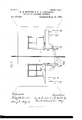
- Fig. 5 is a like view of the mechanism employed for connecting and disconnecting the vibratile reed with the registering mechanism.
- Fig. 6 is a perspective view of the mechanism preferably employed for vibrating a balance or hair-spring; and
- Fig. 7 is a perspective view, partly in section, of our apparatus' as arranged for use.
- Our invention relates to the adjustment of watches, and is designed to facilitate and render more perfect the adjustment of the balance and hair-spring under extremes of temperature, to which end said invention con-.
- Our invention contemplates the vibration of a balance a predetermined number of times in connection with a standard hair-spring within a compartment which has its temperature kept uniformly at one of the extremes and the registration of the time required for such vibrations by mechanism that is outside of such compartment, but is connected with the vibrating mechanism, so that when the latter is started or stopped the former will be automatically and simultaneously set in motion and stopped and will show accurately and in minute divisions the time required for making such vibrations.
- a balance A we preferably employ an ordinary time-train, which is inclosed within a suitable casing B and actuated by a spring or weight.
- the balance-arbor C projects above the said casing, and is provided with a hair-spring D of standard strength, and is adapted to'receive and carry a balance and to permit of the easy placing in or removing of the same from position.
- the time-train is provided with ordinary stop mechanism, which may be released by a push-button E, and when so released will permit the train to run until a certain number of vibrations have been made by the balance, when further motion will be automatically arrested.
- the construction of said vibrating mechanism will be readily understood and requires no special description.
- a vibratilereed F which is constructed from soft iron and has one of its ends secured within a suitable base G, from whence said reed projects upward, as shown.
- a fulcrum-block: H which closely embraces and is adjustable lengthwise of the same, and is supported by or upon a standard G, that extends upward from the base G.
- electro-magnets I and'I Upon opposite sides of the reed F are placed electro-magnets I and'I, which are suitably connected with each other and with a source of electric energy, and operate by alternate attraction to give to said reed avibratory motion in substantially the same manner as in case of the hammer of an electric bell.
- the length of time required for each vibration is determined by the operative length of said reed, and is in no manner dependent upon the strength of the electric current, so that an absolutely uniform rate of motion is obtainedby the action of a current having sufficient strength to set the reed in motion.
- each is secured upon a head or block t, which is adapted to be moved horizontally upon or within the standard G, and is preferably so moved bya screw i, and when in position locked in place by means of another screw t that passes through an elongated opening in said head and has its threaded end contained within said standard.
- a spiral spring I placed between said heads, operates to press the same outward against their regulating-screws 2'.
- Changes of temperature may vary the operative length of the reed F and so change the rate of its movements; but such changes may be compensated for by adjusting the fulerum-block 11 until the sound produced by said reed has the required pitch, as determined by comparison with a tuning-fork, pitch-pipe, or other standard.
- the vibrating motion of the reed F is utilized to give motion to or to permit the movement of a train of gearing in the following manner, viz: Secured to or formed upon the upper end of said reed are two pallets f and f, which are oppositely arranged. and at such relative distance as to permit of the placing between of an escape-wheel K, which wheel is journaled upon a relativelystationary supporting plate or frame L, and is connected with a train of wheels that actuate registerhands M and M.
- the vibrations of the reed F through the pallets f and f cause the wheel K to have a step-by-step rotation and the registering mechanism to be actuated so as to show upon the dials thereof the number of such vibrations during a given time; but if desired said registering mechanism may be driven by a spring or weight and its motion permitted and governed by the reed-actuated escapemeut.
- vibrations of the reed F and the rotation of the escapewheel K shall be constant and that connection between the latter and the registering-train shall be made or broken at the instant when the balance-vibrating mechanism is started or steps.
- This is preferably effected by means of a wheel h, which is journaled upon one end of a pivoted bar 0 and supported in such position that while always meshing with one of the wheels P of the register-train it is capable of being moved into or out of engagement with a wheel is upon the arbor of said escape-wheel by a movement of said bar.
- an eleetro-magnet Q which is connected with a source of electric energy, and such connection opened or closed by means of or through the stop device that releases or arrests the operative mechanism for vibrating a balance, so that upon pressing the button E of the latterthe current is cutoff from said magnet and said bar is free to be moved by a spring 0 so as to cause the wheels h and 7a to mesh and the registering-train to act, while when said step device acts to arrest the motion of said balance-vibrating mechanism it also opens the electric circuit and causes said magnet to move said pivoted bar in an opposite direction and thereby breaks the connection between the vibrating reed and reg istering-train, when the latter will instantly stop.
- the hands of said registering mechanism are set at zero by means of the wellknown devices employed for such purpose, which devices are operated by a push-button R.
- the balancevibrating mechanism is placed within a compartment S, which has its temperature regulated to and kept at the desired point-either the upper or lower eXtre1ne-wl1ilc the registering mechanism is placed within a separate compartment T and connected electrically with the former.
- a balance is now placed in position and vibrated and the time required for such vibrations registered for comparison with an established standard and with the time required for a like number of vibrations of the same balance within the other extreme of temperature, and in consequence of the very fine divisions of time shown by the register, the detection of exceedingly small differences in the lengths of time covered by single vibrations becomes practicable.
- the method employed for testing balances or hair-springs in extremes of temperature which consists in vibrating a balance or hair-spring a predetermined number of times within a compartment having the desired temperature and registering the time of such vibrations within another compartment by connected mechanisms which are simultaneously started and stopped, substantially as and for the purpose specified.
Landscapes
- Physics & Mathematics (AREA)
- General Physics & Mathematics (AREA)
- Percussion Or Vibration Massage (AREA)
Description
(No Model.) 5 Sheets-Sheet 1.
G. E. HUNTER & F. H. GORTHELL. METHOD OF ADJUSTING WATCHES.
No. 437,204. Patented Sept. 30, 1890.
1% W I 5 Z V I Q z i :I' O I I MW/ ,wzmwdaajwz49 fi m 6.4 mm Wax @Auzaflfl r 5 Sheets-Sheet 4. .G. E. HUNTER & F. H. GORTHELL.
(No Model.)
METHOD OF ADJUSTING WATCHES.
Patented Sept. 30, 1890.
l co' Mw 26AM 5 Sheets-Sheet 5.
(No M 0de1.)
G. E. HUNTER & F. H. GORTHBLL. METHOD OF ADJUSTING WATCHES.
-- No. 437,204. Patented Sept. 30. 1890.
"III/III,
5R5 co., mqxmumm, WASHINGTON n c UNITED. STATES PATENT OFFICE.
GEORGE E. HUNTER AND FREDERICK H. CORTHELL, OF ELGIN, ASSIGNORS TO THE ELGIN NATIONAL WATCH COMPANY, OF CHICAGO, ILLINOIS.
METHOD OF ADJUSTING WATCHES.
srEcIrIoArroN forming part of Letters fatent No. 437,204, dated September so, 1890. 7 Application filed September 23,1889- fierial No. 324,821. (No model.)
Watches; and we do hereby declare that the following is a full, clear, and exact description thereof, reference being had to the accompanying drawings, in which Figure 1 is a perspective view of the record- 4 ing mechanism preferably employed. Figs.
2 and 3 are respectively enlarged side and end elevations of the same. Fig. 4 is an enlarged plan View of the upper end of the vibratile reed and the wheel engaged by-the same. Fig. 5 is a like view of the mechanism employed for connecting and disconnecting the vibratile reed with the registering mechanism. Fig. 6 is a perspective view of the mechanism preferably employed for vibrating a balance or hair-spring; and Fig. 7 is a perspective view, partly in section, of our apparatus' as arranged for use.
Letters of like name and kind refer to like parts in each of the figures. I
Our invention relates to the adjustment of watches, and is designed to facilitate and render more perfect the adjustment of the balance and hair-spring under extremes of temperature, to which end said invention con-.
sists in the method employed, substantially as and for the purpose hereinafter specified.
Our invention contemplates the vibration of a balance a predetermined number of times in connection with a standard hair-spring within a compartment which has its temperature kept uniformly at one of the extremes and the registration of the time required for such vibrations by mechanism that is outside of such compartment, but is connected with the vibrating mechanism, so that when the latter is started or stopped the former will be automatically and simultaneously set in motion and stopped and will show accurately and in minute divisions the time required for making such vibrations. 1
In the carrying of our invention into practice many forms ofmechanism may be employed; but it will be sufficient to show the. form which is preferably used.
For the purpose of vibrating a balance A we preferably employ an ordinary time-train, which is inclosed within a suitable casing B and actuated by a spring or weight. The balance-arbor C projects above the said casing, and is provided with a hair-spring D of standard strength, and is adapted to'receive and carry a balance and to permit of the easy placing in or removing of the same from position. The time-train is provided with ordinary stop mechanism, which may be released by a push-button E, and when so released will permit the train to run until a certain number of vibrations have been made by the balance, when further motion will be automatically arrested. The construction of said vibrating mechanism will be readily understood and requires no special description.
For measuring the length of time required for the vibrations of the balance A we employ a vibratilereed F, which is constructed from soft iron and has one of its ends secured within a suitable base G, from whence said reed projects upward, as shown. For the purpose of determining and varying the operative length of said reed its lower portion passes through a fulcrum-block: H, which closely embraces and is adjustable lengthwise of the same, and is supported by or upon a standard G, that extends upward from the base G. Upon opposite sides of the reed F are placed electro-magnets I and'I, which are suitably connected with each other and with a source of electric energy, and operate by alternate attraction to give to said reed avibratory motion in substantially the same manner as in case of the hammer of an electric bell. The length of time required for each vibration is determined by the operative length of said reed, and is in no manner dependent upon the strength of the electric current, so that an absolutely uniform rate of motion is obtainedby the action of a current having sufficient strength to set the reed in motion. In order that said magnets may be easily adjusted with relation to said reed, each is secured upon a head or block t, which is adapted to be moved horizontally upon or within the standard G, and is preferably so moved bya screw i, and when in position locked in place by means of another screw t that passes through an elongated opening in said head and has its threaded end contained within said standard. A spiral spring I, placed between said heads, operates to press the same outward against their regulating-screws 2'.
Changes of temperature may vary the operative length of the reed F and so change the rate of its movements; but such changes may be compensated for by adjusting the fulerum-block 11 until the sound produced by said reed has the required pitch, as determined by comparison with a tuning-fork, pitch-pipe, or other standard.
The vibrating motion of the reed F is utilized to give motion to or to permit the movement of a train of gearing in the following manner, viz: Secured to or formed upon the upper end of said reed are two pallets f and f, which are oppositely arranged. and at such relative distance as to permit of the placing between of an escape-wheel K, which wheel is journaled upon a relativelystationary supporting plate or frame L, and is connected with a train of wheels that actuate registerhands M and M.
As preferably arranged, the vibrations of the reed F through the pallets f and f cause the wheel K to have a step-by-step rotation and the registering mechanism to be actuated so as to show upon the dials thereof the number of such vibrations during a given time; but if desired said registering mechanism may be driven by a spring or weight and its motion permitted and governed by the reed-actuated escapemeut.
It is intended that the vibrations of the reed F and the rotation of the escapewheel K shall be constant and that connection between the latter and the registering-train shall be made or broken at the instant when the balance-vibrating mechanism is started or steps. This is preferably effected by means of a wheel h, which is journaled upon one end of a pivoted bar 0 and supported in such position that while always meshing with one of the wheels P of the register-train it is capable of being moved into or out of engagement with a wheel is upon the arbor of said escape-wheel by a movement of said bar. Opposite to the rear end of the bar 0 is placed an eleetro-magnet Q, which is connected with a source of electric energy, and such connection opened or closed by means of or through the stop device that releases or arrests the operative mechanism for vibrating a balance, so that upon pressing the button E of the latterthe current is cutoff from said magnet and said bar is free to be moved by a spring 0 so as to cause the wheels h and 7a to mesh and the registering-train to act, while when said step device acts to arrest the motion of said balance-vibrating mechanism it also opens the electric circuit and causes said magnet to move said pivoted bar in an opposite direction and thereby breaks the connection between the vibrating reed and reg istering-train, when the latter will instantly stop. The hands of said registering mechanism are set at zero by means of the wellknown devices employed for such purpose, which devices are operated by a push-button R.
In the use of our invention the balancevibrating mechanism is placed within a compartment S, which has its temperature regulated to and kept at the desired point-either the upper or lower eXtre1ne-wl1ilc the registering mechanism is placed within a separate compartment T and connected electrically with the former. A balance is now placed in position and vibrated and the time required for such vibrations registered for comparison with an established standard and with the time required for a like number of vibrations of the same balance within the other extreme of temperature, and in consequence of the very fine divisions of time shown by the register, the detection of exceedingly small differences in the lengths of time covered by single vibrations becomes practicable.
It will be seen that the higher the rate of vibration of the reed, the finer will be the divisions of time shown by the registering mechanism and the smaller the error in the balance which can be detected. It is practicable to secure twenty thousand vibrations of said reed per minute, which will enable an error in the balance of one second in twentyfour hours to be shown.
For testing hair-springs precisely the same mechanism is employed as that described, except that a standard balance instead of a standard hair-spring is secured upon the balance-arbor and provision made for the ready attachment and removal of the hair-springs to be tried.
The mechanism shown and described is not claimed herein, but forms the subject of a separate application for patent, filed February 13, 1890, Serial No. 340,321. Said mechanism is also in part shown and described in. our application filed simultaneously herewith, Serial N 0. 824,820, and one filed February 13, 1890, Serial No. 340,320.
Having thus described our invention, what we claim is- 1. As an improvement in the adjustment of watches, the method employed for testing balances or hair-springs in extremes of temperature, which consists in vibrating a balance or hair-spring a predetermined number of times within a compartment having the desired temperature and registering the time of such vibrations within another compartment by connected mechanisms which are simultaneously started and stopped, substantially as and for the purpose specified.
2. As an improvement in the adjustment of watches, the method employed for testing balances or hair springs in extremes of temperature, which consists in vibrating a balance or hair-spring a predetermined number of times within one compartment and registering the time of such vibrations within an- In testimony that we claim the foregoing we have hereunto set our hands this 16th day of September, 1889.
GEORGE E. HUNTER. FRED H. OORTHELL.
Witnesses W. H. CLOUDMAN, W. P. HEMMENS.
Qerreotions in etiers Patent No. 437,204.
sfff/ It is hereby certified that in Letters Patent No. 437,204, granted September 80, 1890, upon the application of George E. Hunter and Frederick H. Oorthell, of Elgin, Illinois, for an improvement in Method of Adjusting Watches, errors appear in the printed specification requiring correction as follows: In lines 43 and 59, page 2, the reference letters h should read N and that the said Letters Patent should be read with these corrections therein to conform to the papers pertaining to the case in the Patent Office.
sealed this 7th day of October, A. D. 1890.
CYRUS BUSSEY, Assistant Secretary of the II'LMMOT.
Signed, conntersigned, and
[SEAL] Countersigned:
O. E. MITCHELL,
Cormnissimwr 0 7" Patents.
Publications (1)
| Publication Number | Publication Date |
|---|---|
| US437204A true US437204A (en) | 1890-09-30 |
Family
ID=2506106
Family Applications (1)
| Application Number | Title | Priority Date | Filing Date |
|---|---|---|---|
| US437204D Expired - Lifetime US437204A (en) | Method of adjusting watches |
Country Status (1)
| Country | Link |
|---|---|
| US (1) | US437204A (en) |
-
0
- US US437204D patent/US437204A/en not_active Expired - Lifetime
Similar Documents
| Publication | Publication Date | Title |
|---|---|---|
| US1995305A (en) | Method and apparatus for determining the force of gravity | |
| US437204A (en) | Method of adjusting watches | |
| US437206A (en) | Apparatus for adjusting watches | |
| US437203A (en) | Method of adjusting watches | |
| US437205A (en) | Apparatus for adjusting watches | |
| US496728A (en) | Electbic meter | |
| US1951226A (en) | Measurement of gravitational forces | |
| US366202A (en) | Electricity | |
| US650994A (en) | Weighing-scale. | |
| US633471A (en) | Weight and pressure indicator. | |
| US512687A (en) | And thomas r | |
| US572699A (en) | Beverly w | |
| US1131062A (en) | Pedometer attachment for watchmen's portable time-registers. | |
| US402823A (en) | Electric clock | |
| US680888A (en) | Weighing-scale. | |
| US373138A (en) | Clock-synchronizing apparatus | |
| US360234A (en) | Testing and grading watch-balances and hair-springs | |
| US360903A (en) | Albert l | |
| US473341A (en) | phillips | |
| US618670A (en) | Electric clock | |
| US2454983A (en) | Stroboscopic apparatus for calibrating time indicating devices | |
| US490202A (en) | Mechanism for testing watch-balances and hair-springs | |
| US2222032A (en) | Metronome | |
| US636685A (en) | Weight and pressure recording apparatus. | |
| US1509899A (en) | Stop-watch mechanism |