US4369632A - Refrigerated merchandiser display case - Google Patents
Refrigerated merchandiser display case Download PDFInfo
- Publication number
- US4369632A US4369632A US06/141,360 US14136080A US4369632A US 4369632 A US4369632 A US 4369632A US 14136080 A US14136080 A US 14136080A US 4369632 A US4369632 A US 4369632A
- Authority
- US
- United States
- Prior art keywords
- air
- cabinet
- defrost
- band
- during
- Prior art date
- Legal status (The legal status is an assumption and is not a legal conclusion. Google has not performed a legal analysis and makes no representation as to the accuracy of the status listed.)
- Expired - Lifetime
Links
Images


Classifications
-
- F—MECHANICAL ENGINEERING; LIGHTING; HEATING; WEAPONS; BLASTING
- F25—REFRIGERATION OR COOLING; COMBINED HEATING AND REFRIGERATION SYSTEMS; HEAT PUMP SYSTEMS; MANUFACTURE OR STORAGE OF ICE; LIQUEFACTION SOLIDIFICATION OF GASES
- F25D—REFRIGERATORS; COLD ROOMS; ICE-BOXES; COOLING OR FREEZING APPARATUS NOT OTHERWISE PROVIDED FOR
- F25D21/00—Defrosting; Preventing frosting; Removing condensed or defrost water
- F25D21/06—Removing frost
- F25D21/12—Removing frost by hot-fluid circulating system separate from the refrigerant system
- F25D21/125—Removing frost by hot-fluid circulating system separate from the refrigerant system the hot fluid being ambient air
-
- A—HUMAN NECESSITIES
- A47—FURNITURE; DOMESTIC ARTICLES OR APPLIANCES; COFFEE MILLS; SPICE MILLS; SUCTION CLEANERS IN GENERAL
- A47F—SPECIAL FURNITURE, FITTINGS, OR ACCESSORIES FOR SHOPS, STOREHOUSES, BARS, RESTAURANTS OR THE LIKE; PAYING COUNTERS
- A47F3/00—Show cases or show cabinets
- A47F3/04—Show cases or show cabinets air-conditioned, refrigerated
- A47F3/0404—Cases or cabinets of the closed type
- A47F3/0408—Cases or cabinets of the closed type with forced air circulation
-
- F—MECHANICAL ENGINEERING; LIGHTING; HEATING; WEAPONS; BLASTING
- F25—REFRIGERATION OR COOLING; COMBINED HEATING AND REFRIGERATION SYSTEMS; HEAT PUMP SYSTEMS; MANUFACTURE OR STORAGE OF ICE; LIQUEFACTION SOLIDIFICATION OF GASES
- F25D—REFRIGERATORS; COLD ROOMS; ICE-BOXES; COOLING OR FREEZING APPARATUS NOT OTHERWISE PROVIDED FOR
- F25D2317/00—Details or arrangements for circulating cooling fluids; Details or arrangements for circulating gas, e.g. air, within refrigerated spaces, not provided for in other groups of this subclass
- F25D2317/06—Details or arrangements for circulating cooling fluids; Details or arrangements for circulating gas, e.g. air, within refrigerated spaces, not provided for in other groups of this subclass with forced air circulation
- F25D2317/068—Details or arrangements for circulating cooling fluids; Details or arrangements for circulating gas, e.g. air, within refrigerated spaces, not provided for in other groups of this subclass with forced air circulation characterised by the fans
- F25D2317/0684—Details or arrangements for circulating cooling fluids; Details or arrangements for circulating gas, e.g. air, within refrigerated spaces, not provided for in other groups of this subclass with forced air circulation characterised by the fans the fans allowing rotation in reverse direction
Definitions
- the present invention relates to a "reach-in" merchandiser type of refrigerated display case or cabinet used primarily in retail food and supermarket outlets.
- the term "refrigerated”, in accordance with the present invention is intended to incorporate those cases maintained at a temperature at or in excess of 32° F., such as display cases utilized for display for milk and fresh foods, and those cases maintained below 32° F., such as frozen food cases.
- references are made herein to the use of transparent doors, since those are the types of doors most frequently utilized in such retail outlets. Other types of doors could also be employed within the scope of the present invention.
- a system for automatically defrosting the refrigeration coils In the operation of all types of refrigerated display cabinets, it is desirable to include a system for automatically defrosting the refrigeration coils.
- the defrost cycle can be actuated either at set periodic time intervals or when the frost buildup within the system has reached a certain predetermined level.
- Such systems are typically thermostatically controlled so as to switch from a refrigeration cycle to a defrost cycle of operation. In this manner of operation it is possible to avoid any significant frost buildup within the display cabinet such that inoperability and spoilage of food products would occur.
- This invention relates to a "reach-in" transparent door merchandiser type of refrigerated display cabinet having an air defrost system incorporated therein.
- the background of the invention described and claimed in the present application also includes a recognition of the energy conservation trend among managers of retail food outlets to reduce operating costs wherever possible.
- One such area of energy conservation is to provide heat transfer constraining barrier doors across the refrigerated merchandiser display cabinets.
- barrier doors are often constructed of double or triple layer glass or other transparent materials in order to reduce the contact between the ambient air which has high heat and moisture content and the refrigerated air within the display cabinet.
- the refrigerated air band which may be at a temperature as low as -15° F. is contacted by ambient air having a temperature as high as 75° F. This contact can raise the refrigeration load even above that required by multi-air band open front cases having no barrier doors.
- one or two guard air bands which can protect the inner refrigerated band against direct contact with the ambient air when the merchandiser doors are opened.
- Beckwith et al U.S. Pat. No. 3,403,525 also discloses a night curtain which is to be placed over the normally open access area of a refrigerated case in order to reduce energy consumption during the "non-sales" hours, but with this arrangement no air defrost or customer entry is possible.
- U.S. Pat. No. 4,117,698 discloses a retractable night curtain for use during closed store hours during which no provision is made for customer entry.
- An improvement in refrigerated cases is provided in which provision is made for one or more circulated air bands and an air defrost means which functions to selectively create a gap between a barrier door and the associated access opening to effect defrosting in a simple and low energy consumption manner.
- the air defrost means also includes an air moving means for passing ambient air through the cabinet and through the gap between the door and the access opening to bring the ambient air into contact with refrigeration elements in the cabinet to remove accumulated frost therefrom and to thereafter eject the defrost ambient air from the cabinet.
- the gap created between the barrier door and the access opening is thus part of the flow path of the ambient air being passed through the refrigerated cabinet to effect the defrosting function.
- the invention encompasses the use of such an air defrost means to selectively create a gap between the barrier door and the access opening of refrigerated display cabinets having only a single circulated, refrigerated air band propelled within an air conduit or having a plurality of circulated air bands therein of the type which are often used in food outlets without heat transfer barrier doors.
- air bands When a plurality of air bands are included in the cabinet one of these will function as a guard band and can be operated only when needed due to expected or actual use conditions in the store.
- an object of the present invention to provide an improved ambient air defrost means for a refrigerated display cabinet having a customer access opening therein covered by a movable door which provides for low energy consumption operation.
- Still another object of the present invention is to provide a reach-in refrigerated merchandiser display cabinet or case utilizing an improved ambient air defrost system.
- a still more specific object of the present invention is to provide a glass door merchandiser refrigerated display cabinet utilizing an improved ambient air defrost system wherein during the defrost operation ambient air is drawn into the cabinet and circulated through at least a substantial portion of the primary refrigerated air conduit and is thereafter expelled from the cabinet by utilizing an air flow path which passes through a gap created between the glass door and an access opening which is covered by the door.
- FIG. 1 is a perspective view of a reach-in merchandiser type of refrigerated display case in accordance with the present invention
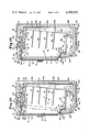
- FIG. 2 is a side cross-sectional schematic view of the refrigerated display case illustrated in FIG. 1 taken on line 2--2 when such display case is operated during a refrigeration cycle;
- FIG. 3 is a schematic view of the refrigerated display case illustrated in FIG. 2 when such display case is operated during a defrost cycle of operation;
- FIG. 4 is a perspective schematic view of a portion of the display case shown in FIGS. 1-3, showing a detail view of the door opening mechanism which is part of the air defrost system;
- FIG. 5 is a top plan schematic view of the top right front corner portion of the display case shown in FIG. 1 which shows the door opening mechanism of the air defrost means;
- FIG. 6 is a fuller detail side cross-sectional view of the display case illustrated in FIGS. 1-3 taken on line 6--6 of FIG. 1 when such case is operated in a defrost cycle;
- FIG. 7 is side cross-sectional schematic view of an embodiment of the present invention, shown in the refrigeration cycle, in which an air flow guidance means deflects air from the secondary conduit into the primary conduit during the defrost cycle;
- FIG. 8 shows a schematic view of the case illustrated in FIG. 7 operating in a defrost cycle with a gap created between the door and the access opening;
- FIG. 9 is an enlarged side cross-sectional view showing the air flow guidance means in Block IX in FIG. 7 in fuller detail;
- FIG. 10 is a cutaway schematic view of the inside front of a refrigerated case illustrating the air flow guidance means shown in FIG. 9;
- FIG. 11 is a cutaway perspective schematic view of the air flow guidance means shown in FIGS. 9 and 10;
- FIG. 12 is a side sectional schematic view of a second embodiment of an air flow guidance means when positioned in a refrigeration mode of operation;
- FIG. 13 is a side schematic sectional view of the air flow guidance means shown in FIG. 12 in a defrost mode of operation;
- FIG. 14 is a cutaway perspective view of the air flow guidance means of the second embodiment of the air guidance means shown in FIGS. 12 and 13;
- FIG. 15 is a enlarged side sectional view of block XV of FIG. 7 showing details of the operation of the two directional secondary air conduit fan;
- FIG. 16 is a side cross-sectional schematic view of another embodiment of the present invention having a common inlet chamber for both primary and secondary conduits, shown in a refrigeration cycle;
- FIG. 17 is a side cross-sectional view of the cabinet illustrated in FIG. 16 shown in a defrost cycle with the door opened;
- FIG. 18 is a side sectional schematic view of another embodiment of the refrigerated display cabinet in accordance with the present invention shown in a refrigeration cycle of operation wherein an auxiliary ambient air fan is provided;
- FIG. 19 is a side sectional schematic view of the embodiment of the display cabinet of FIG. 18 shown in a defrost cycle of operation;
- FIG. 20 is a side sectional schematic view of another embodiment of the refrigerated display cabinet wherein a single air conduit is provided and an additional air passage port is located in the top wall of the cabinet as seen in a refrigeration mode of operation;
- FIG. 21 is a side sectional schematic view of the embodiment shown in FIG. 20 wherein the air passage port is shown in an open position during a defrost mode of operation;
- FIG. 22 is a schematic diagram of the control hierarchy involved in the operation of the refrigerated display case.
- an upright refrigerated display cabinet or case assembly has a front wall 12, side walls 14, top wall 16 and an insulated rear wall 18, which are best shown in FIG. 2.
- Display case 10 has an opening 20 in its front wall 12 which is covered by one or more barrier doors illustrated by five doors 22, 24, 26, 28 and 30.
- Each door is attached to the display cabinet by vertical hinge pins shown as 31 in FIG. 4 and each door has a handle shown as 32, 34, 36, 38 and 40, respectively.
- Upper and lower bumper guard rail 39 and 41 are also provided on front wall 12.
- Such a refrigerated display cabinet is typically referred to as a glass-door merchandiser even though transparent material other than glass such as plastic can be used in the doors.
- Merchandiser refrigerated display cabinets can be used for storing either fresh foods, such as dairy products, or frozen foods requiring lower temperatures.
- the interior of the display cabinet shown in FIG. 2 has a display space 42 in which there are arranged a plurality of display shelves 44, 46, 48 and 50, although more than four such shelves can be employed as illustrated by shelf 52 in FIG. 1.
- Each shelf can be supported by a plurality of vertically adjustable support brackets 45, 47, and 49 are shown for shelf 44 in FIG. 1.
- the space at the bottom of the shelves can be used as a storage space 53 and can have a shelf 54 at the bottom thereof as shown in FIGS. 2 and 3.
- Access to the refrigerated products on the display shelves is provided to customers and employees by opening one or more of the doors and reaching into the case through access opening 20.
- a primary air conduit 56 Disposed about display space 42 is a primary air conduit 56 which is formed on the interior side by top panel 58 rear panel 60 and bottom display panel 62 which also form the interior surfaces of display space 42.
- the primary air conduit 56 is formed on the exterior side by an upper divider panel 64 which is connected along the rear edge thereof to a vertical divider panel 66 which extends downwardly and parallel to rear panel 60. Both panel 64 and 66 are shown, constructed of sheet metal although laminates of metal, plastic, and insulation can be used.
- Vertical divider panel 66 is connected along the lower edge thereof to bottom separator panel 68 which extends above and spaced away from bottom insulated panel 70.
- Bottom separator panel 68 is connected at the front edge thereof as shown in FIGS.
- an inclined front separator panel 72 which is, in turn, joined to a substantially vertical front divider panel 74.
- An inclined bottom member 76 is connected to the front edge of bottom panel 70 and is connected at its front most edge with the bottom of front wall 12 which extends upwardly and provides front support for an air grille 78 which then extends from the front wall 12 in an arcuate fashion into bottom storage space 53.
- bottom panel 70 is connected to rear wall 18.
- the top portion of rear wall 18 and part of top wall 16 incorporate a secondary air conduit fan housing 80 which is constructed of a top panel 82 connected along the top edge of rear panel 18 and along the front edge thereof to vertical exterior member 84 which is connected by the lower edge thereof to top panel 16.
- the outermost conduit formed between top wall 16 and upper divider panel 64 at the top of the cabinet and extending vertically downward between divider panel 66 and rear panel 18 forms a secondary air conduit 86 which extends between bottom separator panel 68 and bottom panel 70 in the lower portion of the cabinet.
- Support feet 88 and 90 are also provided for bottom wall 70.
- This refrigeration means consists of a sheet metal box in which a plurality of refrigeration evaporation coils are arranged.
- the sheet metal sides have openings to allow for passage of one or more air band as illustrated in the various figures by the air flow arrows and perforations.
- the primary air band propelled through conduit 56 by fan 98 is maintained in a refrigerated, low temperature condition during the refrigeration cycle of operation of cabinet 10.
- the upper front portion of secondary air conduit 86 formed between upper separator panel 64 and top wall 16 terminates in a secondary air conduit outlet opening 104 in which are positioned downwardly oriented directional louvers 106 which function to direct the air flow downwardly across the inside of door 24 as shown by the secondary air guard band indicated by arrows B in FIG. 2.
- the secondary air band enters air grille 78 at the bottom portion of door 24 and then into a secondary conduit air inlet opening 108 which is associated with air grille 78.
- the inlet and outlet openings of the secondary air conduit are also positioned in aerodynamic alignment. This secondary air inlet opening is separated from the primary conduit inlet opening 96 by the top front portion of front divider panel 74.
- the secondary air band B is propelled downward through the outlet opening 106 and into inlet opening 108 and then between front separator panel 72 and inclined bottom member 76 and thereafter between separator panel 68 and bottom panel 70 then upwardly in conduit 86 between vertical divider panel 66 and rear wall 18 by means of a motor-driven secondary conduit fan 110 mounted in baffle 112 positioned within fan housing 80 at the top of the case 10.
- FIG. 1 shows door opening mechanisms 114, 116, 118, 120 and 122 connected on top wall 16.
- mechanism 116 is an electric motor and gear box which operates a linkage-rotating rod-lever system to open door 24.
- Door opening mechanism 116 is best shown in FIG. 4 wherein a electric motor and gear box 124 is mounted on top wall 16 and has a swing arm 126 attached to its output shaft. Arm 126 is pivotally linked at its opposite end to member 128 which is in turn pivotally linked to rod 130 which has a vertical portion 132 which passes through and is rotatably supported within top wall 16. The bottom of vertical portion 132 is integrally connected to an operator lever 134 which contacts stud 136 secured to the top portion of door 24 as shown in FIG. 4. When door opening mechanism 116 is activated it moves from the closed position shown in dotted lines to the open position shown in solid lines so that door 24 is opened by reason of movement of operator lever 134 against stud 136.
- Operation of the enclosed motor in an opposite direction causes the door opening mechanism shown to return to closed position.
- Springs (not shown) can be included in connection with the door hinge pins or links 126-134 to assure prompt closure of door 24 which can preferably have a substantial area of transparent material such as glass or plastic shown as 138.
- operator lever 134 can be bifurcated so that it straddles stud 136 and moves door 24 positively in both the opening and the closing directions.
- Another configuration for the door operating mechanism is that a plurality of solenoids can operate directly against the doors to open the same or a single solenoid operating a multiple cam arrangement can open all doors or only selected doors.
- Door opening mechanism 116 and the associated arms, rods and linkages provide an air defrost means for selectively creating a gap between the barrier door 24 and the access opening 20.
- ambient air is drawn into and/or expelled out of the cabinet 10 through the gap G. This ambient air inflow is shown by dashed arrows C in FIG. 4.
- FIG. 5 shows three such door opening mechanisms 118, 120 and 122 and associated links 140, 142 and 144 for opening doors 26, 28 and 30, respectively.
- FIG. 3 A preferred mode of defrost operation of cabinet 10 is shown in FIG. 3 wherein door 24 has been opened by door operating mechanism 116 and ambient air (illustrated by dashed arrows C) is drawn through the upper portion of the gap G into the primary air conduit outlet opening 92 and into the primary air conduit 56 by means of the primary conduit fan 98 being operated in reverse direction from that shown in FIG. 2 for the refrigeration cycle of operation.
- the ambient air thus drawn into cabinet 10 is propelled through the primary conduit 56 as shown by the dashed arrows around the periphery of display space 42 downwardly in the rear portion of the primary conduit 56 and between bottom panel 62 and bottom separator panel 68 and then up to the front of the primary conduit 56.
- the primary air band with the entrained ambient air C is then caused to continue flowing upward and outward of cabinet 10 through the lower portion of gap G, created between door 24 and access opening 20.
- the warmer ambient air raises the temperature of the air flowing in the primary conduit and melts the frost and ice which has accumulated on refrigeration element 102.
- the secondary conduit fan 110 is not operated during this preferred defrost cycle and hence secondary air flow is dormant.
- the reversed flow air system arrows have been labeled D in conduit 56 after contact with element 102 since the primary conduit air band is then a defrost ambient air band.
- the speed of the primary conduit fan 98 can be increased during this reverse flow and/or the pitch of the blades can be set to move a greater volume of air in the reverse, defrost direction than in the refrigeration cycle shown in FIG. 2 to provide quicker defrost. A 25% to 50% greater air flow during defrost can be achieved in this manner.
- the water created by this defrost action is then drained from the bottom of cabinet 10 by drain 146 which is arranged at the convergence of the downward sloping bottom panel 70 and inclined bottom member 76.
- control means operates door operating mechanism 116 to allow door 24 to close and for fan 98 to then reverse its direction to re-establish the primary, refrigerated air band A shown in FIG. 2.
- secondary fan 110 can be engaged for operation under one of the operating alternatives as described below.
- a plurality of conduit fans illustrated by primary conduit fan 98 and the secondary conduit fan 110 shown in FIGS. 2 and 3 are spaced along the length of cabinet 10 shown in FIG. 1.
- two each of these fans are normally provided for an eight foot long case or three each of the primary and secondary fans are provided for a twelve foot case.
- the overall height of cabinet 10 is approximately 82 inches and the width is approximately 45 inches.
- Such cabinets are manufactured in lengths up to 72 feet.
- the control means can be fabricated from conventional components, although arrangement of these components can result in several degrees of freedom in the operation of the cabinet.
- the control means can function during the refrigeration cycle as shown in FIG. 2 wherein air fans 98 and 110 are continuously operated and refrigerant is evaporated in low temperature element 102 as needed in order to maintain the low temperature required by products stored in display space 42. During the refrigeration cycle the door is closed as shown in FIG. 2.
- Door switches can be provided for operation by any of the doors so that the secondary conduit fan 110 closest to the access opening covered by that door will be activated upon the opening of the door.
- a switch can be installed within cabinet 10 to be operated when the door it open.
- the opening and closing of the doors by customers and employees can be used as numerical input to an electronic counting circuit so that the secondary fan 110 is operated whenever a particular frequency of openings per time period is exceeded.
- cabinet 10 can be provided with a control means which is responsive to the shopping demand placed on the unit.
- This type of sensing means to provide signals for the control means can be provided for all barrier doors or only spaced and selected doors. The sensing switches can be set so that they do not sense the defrost cycle opening of the doors by the door operating mechanisms.
- Yet another variation can be the operation of secondary fan 110 depending upon the temperature and humidity conditions in the ambient store air or in the cabinet display space.
- the defrost cycle of operation for cabinet 10 can be initiated by sensing the temperature at locations spaced slightly away from the coils in low temperature element 102 so that the buildup of a predetermined thickness of frost and ice on the coils will activate the sensing element which can then initiate a defrost cycle.
- Another means is a timer which controls the defrost cycles initiations at set intervals. Other variations are to record store ambient conditions, particularly relative humidity, and to vary the time cycle of defrost depending on such conditions.
- the number of openings of the cabinet doors can also be included as a control feature as above described and referenced to the operation of the secondary conduit fan 110.
- the refrigerant evaporation in low temperature element 102 is terminated; door operating mechanism 116 is operated to open the doors as illustrated in FIG. 5; secondary conduit fan 110 is preferably stopped; and primary conduit fan 98 is reversed so that the air flow pattern is as shown in FIG. 3, whereby ambient air enters the top portion of the gap created between the barrier door 24 and the access opening 20 and then ambient air flows through primary conduit 56 in a reverse direction in order to contact the frost and ice coated coils in low temperature element 102 and thereafter the resultant defrost ambient air is expelled from the bottom portion of the gap as shown.
- the defrost cycle can continue until a preset time is exceeded or a temperature measurement can be taken in the close proximity of the coils in low temperature element 102 so that the defrost cycle is terminated when that sensed point in element 102 reaches a predetermined temperature, for example 50° F., for which purpose a sensor known as a Klixon can be employed.
- a predetermined temperature for example 50° F., for which purpose a sensor known as a Klixon can be employed.
- FIGS. 1-22 The operation of the air defrost refrigerated cabinet 10 described by FIGS. 1-22 can be carried out according to the various modes of operation disclosed above for the secondary air band flow, reversing of the primary air band flow direction, and opening of the barrier doors if these modes are not contrary to the sequence of operations disclosed herein for the various embodiments.
- FIG. 6 Additional details of the refrigerated cabinet illustrated in FIGS. 1-3 are shown in FIG. 6.
- Line 6--6 shown on FIG. 1 has been taken during a defrost cycle when door 28 is open.
- the door 28 consisting of an inside glass pane 150 and an outside pane (which is not viewable) supported by an upper frame member 152 and a lower frame member 154.
- the upper and lower frame members are connected by a front frame piece 155 and a rear frame piece 156.
- a bottom hinge pin 157 is shown for lower frame member 154 and a similar hinge pin 31 is provided for the upper frame member 152.
- the bottom hinge pin 157 is shown supported by the top portion of the lower light fixture bracket 158 mounted on front wall 12 and top hinge pin 31 is shown supported in top cowl 159, although intermediate door frame members can be used to provide this support.
- a stud 160 is secured to the top edge of door frame member 152 and this corresponds to stud 136 shown in FIG. 4. Stud 160 is secured to the frame of door 28 which is opened by door operating mechanism 120 and its associated rod and linkage mechanism 162 which is identical to mechanism 116 and associated links 128-134 described in reference to FIG. 4.
- Rotatable vertical rod 164 is integrally connected at its lower end to operator lever 166.
- the operation of mechanism 120 causes operator rod 164 to rotate lever 166 and force door 26 open by reason of contact against stud 160.
- Cabinet 10 is shown in FIG. 6 is equipped with an upper light fixture 168 which, typically, is arranged to accommodate a longitudinal series of fluorescent bulbs 170.
- a door frame mullion 172 is supported at its upper end by top cowl 159 and at its lower end by lower light fixture bracket 158 which is arranged to accommodate a fluorescent bulb 174 and a light guard 176 formed of a translucent material.
- the mullion 172 can be connected at upper and lower ends to intermediate door frame members (not shown which can also provide the hinge support for the cabinet doors).
- the door frame mullion 172 is one of a plurality of such mullions spaced longitudinally in access opening 20. Thus this access opening is divided into a plurality of access openings by this construction which are then covered by a plurality of doors such as shown in FIG. 1.
- Shelf support bracket 47 is shown attached to the underside of shelf 44. Brackets 178, 180, and 182 can be provided for shelves 46, 48 and 50 respectively.
- additional vertical fluorescent lights can be attached to vertical mullions 172 to provide additional light for display space 42.
- Separator panels 68, 72 and divider panel 74 are provided in the bottom space in cabinet 10 for separating the bottom portion of primary conduit 56 from secondary conduit 86.
- Vertical divider panel 66 is shown separating these two conduits 56 and 86 at the back portion of cabinet 10.
- Suitable longitudinally spaced support members (such as spacer members 242 in FIG. 14) are provided in the construction of cabinet 10 for securing these and other described panels in the various embodiments in affixed relationship to one another.
- Bottom drain 146 can be of inverted T-type configuration as shown in FIG. 6 and attached to a closable front pipe 186 and a rear pipe 188 for connection to drainage lines.
- An end panel trim member 190 is shown attached to the outer edges of end panel 14 at the front side thereof.
- a top trim member 192 is shown at the top of wall 16.
- Another trim member 194 is provided for the back edge of end panel 14.
- Bottom trim members 196 and 198 are also provided as are support feet 200 and 202.
- Other members such as fan 98 and support bracket 100 are shown in slightly greater detail than in FIGS. 2 and 3 above.
- the bumper guard rails 39 and 41 are shown at the lower portion of the front part of cabinet 10.
- FIG. 6 shows the cabinet in defrost operation after door operating mechanism 120 has caused vertical rod portion 164 to rotate and cause operator lever 166 to engage stud 160.
- Ambient air indicated by dashed arrows C is drawn into cabinet 10 and into primary air conduit 56 and then along the rear portion of conduit 56 by primary conduit fan 98 operating in a reverse direction.
- the defrost air is then forced through the evaporator coils 102 and exhausted from the display space 42 through the lower portion of gap G created between door 28 and access opening 20.
- the air flow directions and the refrigeration and defrost positions of the various elements of the cabinet illustrated in FIG. 6 are shown by schematic FIGS. 2 and 3, above.
- FIG. 6 Also shown in FIG. 6 is an additional set of evaporator coils 210 located adjacent to and slightly above the coil box 102.
- FIGS. 7-15 illustrate an embodiment of the present invention wherein the secondary conduit fan can be used to assist in providing for ambient air intake into the refrigerated cabinet.
- a continuous refrigerated, primary band of air is provided in order to better protect the refrigerated state of the contents stored in display space 42.
- FIGS. 7 and 8 show this embodiment of the refrigerated cabinet in schematic views while FIGS. 9-15 show details of the construction. Since the cabinet structure is largely the same between the first and second embodiments consistent descriptive numerals have been employed except where different or modified elements are shown.
- FIGS. 7 and 8 show a cabinet similar to that shown in FIGS. 1-3 with the exception that an air guidance means is provided by deflector plate 220 located in the front divider panel 74 which separates primary air conduit 56 from secondary conduit 86.
- An air opening 222 is provided to allow the passage of air from conduit 86 into conduit 56 as shown by the dashed arrow labeled C in FIG. 8.
- the secondary conduit fan 110 is powered by a reversible motor 224 so that during the defrost cycle of operation shown in FIG. 8 when door 24 is opened by door operating mechanism 116 ambient air can be drawn in through the gap created between door 24 and access opening 20 as shown by dashed arrows labeled C at the top portion of FIG. 8.
- the secondary air band in the secondary conduit 86 then flows in a reverse direction to the direction shown during the refrigeration cycle in FIG. 7 and continues in conduit 86 under the bottom separator panel 68 and then encounters deflector plate 220 which diverts a portion of the secondary defrost air band as shown by dashed arrow C into the primary conduit 56 and the resulting mixed primary and secondary ambient air is then forced by fan 98 through low temperature element 102 and then upwardly through primary conduit 56 at which point the ambient air has been somewhat reduced in temperature by contact with the ice and frost coating the coils in element 102. This defrost ambient air is then propelled out of primary outlet 92 at the top of cabinet 10.
- This defrost air band then moves vertically downward as shown by arrows D and a portion of the air band is expelled from the bottom portion of gap G created between door 24 and access opening 20.
- the expelled defrost air volume is equivalent to the intake ambient air volume.
- the blade pitch and motor speed for fan 110 can be controlled to deliver a greater air flow during defrost to reduce the time required for de-icing. A 25% to 50% greater flow can be used for the defrost cycle. In this manner both fans function to draw in ambient air and defrost low temperature element 102 without the need for additional energy input by way of heating rods or compressed refrigerant gas loops which have been employed in the prior art.
- Deflector plate 220 does not extend across the entire length of front divider panel 74.
- An interior front bottom panel 226 can be provided for channeling the primary air band flow and does extend across the entire length of the cabinet.
- the deflector plate 220 is preferably provided in the form of a plurality of cover plates 228 which have arcuate cross-sections and extend traversely on either side of front divider panel 74 substantially across each of the air conduits 56 and 86 and thus partially underlie the upper part of associated air grille 78.
- the cover plates 228 are secured on the front edge thereof to outer cabinet front wall 12 and on their inner edges to bottom front interior panel 226 which is a downward extension of bottom display panel 62.
- FIGS. 9-11 The construction of an air guidance means as shown in FIGS. 9-11 for deflecting at least a portion of the reversed flow secondary air band into the primary air conduit is substantially similar to that shown in U.S. Pat. No. 4,144,720 to Subera, and assigned to the same assignee as is the present application.
- FIGS. 12-14 a second embodiment of the air flow guidance means illustrated in FIGS. 9-11 is shown.
- the arcuate cross-section cover plates 228 are replaced by a baffle plate 236 which is provided with a pivot pin 238 at its center.
- front divider panel 74 is terminated at a lower position as shown in FIGS. 9-11 in order to contact the lower edge portion of baffle plate 236 as it is pivoted into open position by a motor and articulated arm mechanism 240 as shown in FIG. 12 in the refrigeration cycle or mode of operation.
- Both arcuate-shaped cover plates 228 and pivotable baffle plates 236 and the associated structural members function as air band diverters in order to provide an air flow guidance means to communicate the secondary air conduit 86 with the primary air conduit 56 in order to guide the secondary air band having co-mingled ambient air therein across the evaporator coils of the refrigeration means in order to defrost the same in the defrost mode or cycle of operation.
- air grille 78 can be constructed in part by tubes 248 which contain circulate hot refrigerant drawn from the compressor prior to the evaporator stage.
- FIG. 15 shows the refrigeration cycle direction of operation of the secondary conduit fan 110 by the solid arrow F.
- the defrost cycle of operation of fan 110 in the reverse direction is indicated by the dashed arrow labeled R.
- the secondary air band flow in refrigeration cycle is labeled B and shown by solid arrows and the air flow during defrost cycle is labeled C and shown by dashed arrows.
- Fan 110 is shown attached to and propelled by reversible motor 224 which is supported on L-shaped bracket 112 by supports 250 and 252.
- This primary air band A is then propelled out of outlet 92 and through downwardly directed louvers 94 and then along the front portions of the shelves as described above.
- the secondary air band B flows in a parallel path out of outlet 104 and through downwardly directed louvers 106 and then at the bottom of cabinet 10 into air grille 78 and thereafter into common conduit chamber 256.
- Fan 258 and motor 260 then force part of the commingled air streams into secondary air conduit 86 located immediately below low temperature element 102.
- This secondary air stream is then propelled upwardly in the secondary air conduit 86 formed by rear wall 18 and the rear divider panel 66.
- heated liquid lines 266 can be provided in association with air grille 78 in the manner described with respect to FIGS. 9, 12 and 13.
- a bottom drain 146 is provided and an insulated bottom panel 62 as in FIGS. 1-6.
- FIGS. 18 and 19 show another modification of the refrigerated cabinet 10 wherein an auxiliary air fan 270 is mounted in a hood 272 arranged on top of wall 16.
- an auxiliary air outlet opening 274 is positioned between the secondary conduit outlet opening 104 and light support housing 276.
- Auxiliary air outlet 274 is also equipped with downwardly directed louvers 278 in order to channel the auxiliary air flow in an initial downward direction.
- Such as tertiary air band propelling means is operated only during the defrost cycle in order to increase the intake of ambient air into cabinet 10.
- Auxiliary fan 270 is not operated in the refrigeration cycle since the cabinet is operated in the refrigeration cycle without significant inflow or outflow of ambient air.
- auxiliary fan 270 is activated after door 24 has been partly opened by door operating mechanism 116 in order to provide an additional tertiary air band which is propelled downward from louvers 278.
- This auxiliary air band is then drawn into the primary conduit louvers 94 covering the primary conduit outlet 92 to thus entrain and commingle additional ambient air C which is drawn into cabinet 10 through gap G.
- This modification functions to increase the air temperature and through-flow in the reverse flow primary air band so that the evaporator coils of the refrigeration means are more quickly defrosted.
- the door opening mechanism 116 can be mounted directly on the light support housing 276 and the rotating operator rod 132 can be supported by a support cowl 280 which is attached to light housing 276. Operation of door opening mechanism 116 is the same as described with respect to FIGS. 1-6 above.
- FIGS. 18 and 19 The modification of cabinet 10 shown in FIGS. 18 and 19 has three low temperature elements 282, 284 and 286 arranged in primary air conduit 56 and numbered in the direction of the primary air band flow during the refrigeration cycle as shown in FIG. 18. Air flow is in the direction of the solid arrows and passes through those portions of these low temperature elements as shown by the perforations 288 and 290.
- a bottom drain 146 with connected tubes 186 and 188 are provided similar to the detailed view of cabinet 10 shown in FIG. 6.
- Other elements such as bottom light housing 172 and the insulated outer wall structure are similar to those shown in FIG. 6.
- a control housing 292 is fit between secondary fan housing 80 and auxiliary fan hood 272 at the top cabinet 10.
- This housing can be used to store automatic control circuitry and equipment for sensing the ambient conditions of the store in which cabinet 10 is positioned and for a conductor wire-way.
- a double row of lights 294 and 296 are shown in light housing 276, and correspond to light bulb 168 shown in FIG. 6.
- a bumper rail 298 and the end panel trimming 300 which extends beyond end panel 14.
- Support legs 302 and 304 are also provided for this cabinet structure.
- a storage space 306 is provided in the bottom part of display space 42 for the storage of products which require refrigeration.
- the primary and secondary conduits 56 and 86 are closely similar to those described with respect to FIGS.
- a bottom divider panel 68 is provided and is connected to a front inclined divider panel 72 which is in turn connected to a vertical divider panel 74 which extends up to the underside of air grille 78 thereby forming the inlets for the primary and secondary conduits 96 and 108, respectively.
- the secondary air band B enters inlet 108 and proceeds through conduit 86 under propulsion of the secondary fan 110 located in secondary fan housing 80 at the top of the cabinet. Secondary air conduit 86 then continues at the top of the cabinet between top wall 16 and upper divider panel 64 which is shown as an insulated panel.
- the secondary conduit outlet 104 is positioned at the terminal end of the secondary conduit 86 which has downwardly directed louvers 106 as shown in FIGS. 1-3.
- refrigerant flow in the coils of low temperature elements 282, 284 and 286 is terminated, door operating mechanism 116 rotates rod 132 in order to open door 24 and to create the gap G shown in FIG. 19, secondary fan 110 operation is terminated, and primary fan 308 reverses its rotational direction in order to move air band A in the opposite direction, and auxiliary fan 270 operation is initiated.
- Ambient air, C is then propelled by auxiliary fan 270 through downward directed louvers 278 and additional ambient air is drawn in by aspiration action through the top portion of gap G and into the primary conduit downward directed louvers 94 and the associated primary conduit outlet 92 in order to pass ambient air with its higher temperature and specific heat through the coils of, first, low temperature element 286 and thereafter elements 284 and 282 as shown in FIG. 19.
- the defrost air shown by dashed arrows is then expelled from cabinet 10 through the lower portion of gap G.
- door 24 is closed by operation of door operating mechanism 116, the operation of auxiliary fan 270 is terminated, refrigerant is again pumped through the coils in elements 282, 284 and 286, and secondary fan 110 is initiated along with primary conduit fan 308 now operated in the refrigeration air flow direction as shown in FIG. 18.
- FIGS. 20 and 21 illustrate another embodiment of the cabinet 10 wherein only a single air conduit 310 is arranged between the outer walls 12, 14, 16, 18 and 70 and the panels forming display space 42.
- an air passage port 312 is arranged in the rear portion of top wall 16 and is covered during the refrigeration cycle of operation by closure of lid 314 against a ring seal 316.
- Closure lid 314 is hinged at the front edge thereof by hinge 18 and is operated by a motor and linkage mechanism 320 which is composed of motor 322 and linkages 324 and 326 which are hinged by pin 328.
- closure lid 314 is opened by operation of motor 322 and ambient air C is drawn into air conduit 310 as shown in FIG.
- the air conduit fan 330 which, in this modification, is a reversible fan.
- the door operating mechanism 116 causes door 24 to open so that the defrost air, D, can be ejected at the bottom portion of gap, G.
- a barrier baffle 332 can be attached to the under surface of closure lid 314 in order to close off the top portion of air conduit 310 so that ambient air enters substantially through air passage port 312 rather than being drawn through the gap G created between the top of door 24 and the access opening 20.
- the access opening 20 and air passage port 312 thus provide aperture means for cabinet 10 which was provided solely by the gap between the door or doors and the access opening or openings in the previously described embodiments.
- a single evaporator coil set 334 has been shown positioned in the bottom portion of air conduit 310 in FIGS. 20 and 21.
- the other elements of the modification of the refrigerated cabinets shown in FIGS. 20 and 21 are substantially similar to the corresponding elements in the embodiment of cabinet 10 illustrated in FIGS. 16 and 17 and hence consistent character numerals have been employed.
- liquid lines 338 can be provided as part of the grille structure at inlet opening 336. Refrigeration system liquid flowing between the condensor and the evaporator coils is pumped through liquid lines 338 in order to raise the temperature of the grille work sufficiently to eliminate frost buildup thereon. Support legs 340 and 342 can also be provided.
- door operating mechanism 116 opens door 24 and creates a gap, G, between the door and its associated access opening 20; motor 322 operates through linkages 334 and 326 to open closure lid 314 to thereby communicate ambient air C with the rear portion of air conduit 310; air conduit fan 330, now operated in a reverse direction, propels the ambient air, C, through low temperature element 344 which is located within conduit 310 so that all air being propelled by conduit fan 330 is drawn through the coil of the low temperature element.
- defrost air band is then expelled from cabinet 10 through the lower portion of gap, G, in a manner similar to that described for operation of the cabinet in FIGS. 16 and 17.
- door 24 and closure lid 314 are returned to the position shown in FIG. 20 and air conduit fan 330 is operated in the refrigeration air flow direction as shown by the solid arrows in FIG. 20.
- An air passage port of the type described can also be provided for interconnection with the primary air conduit in FIGS. 1-6 and 16-19 to allow improved air flow patterns when the defrost ambient air is propelled upward in the primary air conduit during the defrost cycle. In this manner the defrost air can be ejected from the top of the cabinet 10.
- the defrost cycle encompasses the steps of causing ambient air to be drawn into the cabinet and to pass across the refrigeration means and through some portion of the primary air conduit and to be expelled from the cabinet, and of creating a gap between the barrier door and the access opening to enable ambient air through-flow.
- the ambient air can be made to flow in either the primary and/or secondary air conduits. Ambient air contact with the refrigeration means is common to these embodiments.
- FIGS. 7-21 can be intercombined so that various features of the modifications can be employed to optimize operation of cabinet 10 and the energy requirements therefor.
- the provision of the air defrost means of the present invention embodied in the door opening mechanisms of the type illustrated by numeral 116 and the air defrost means which operates this mechanism and the reversible fans in the primary and/or secondary conduits, in the several embodiments, overcomes the above described problems by allowing the barrier doors to be partially opened and the defrost ambient air to be drawn in and ejected through the gap created between the open barrier doors and the access opening. In this manner low energy operational advantages of both barrier doors and circulating air bands can be provided for refrigerated glass door merchandiser type cabinets.
- Open front refrigerated display cabinets conventionally have control means 346 for operating refrigeration means 348 and air moving means 350, connected by dashed control line 352, in order to permit operation in a refrigeration and a defrost cycle.
- Devices such as cabinet condition sensors 354, ambient condition sensors 356 and timers 358 are also provided as set forth in the above MODES OF OPERATION section.
- the display cabinet 10 shown in FIG. 1 is provided with an air defrost means 360 which controls the door operating mechanisms 114, 116, 118, 120 and 122 represented by the block 362.
- the air moving means 350 which controls the power to the first, second and auxiliary air fan sets is then connected through the air defrost means for control thereof during the defrost cycle.
- Various air fans of the air moving means 350 can also be selectively controlled during portions of the refrigeration cycle by signals such as those generated by a demand counter circuit 364 activated by a door operated switch. The signal input is fed into the control means and used to selectively control power to the air moving means fans or sets of fans.
- a counting circuit can be provided within block 364 to initiate a defrost cycle when a predetermined number of door openings occur in relation to time or other conditions.
- the internal circuitry used within blocks 346, 360 and 364 need only be consistent with these and the other disclosed modes of operation in order to control power to the various operating devices.
- the control means can selectively operate the air moving means independently of the door opening mechanism 362 via line 352, for example, when the demand counter is used. This type of control during the refrigeration cycle permits the secondary fans illustrated by fan 110 to be switched on only when the barrier door is opened so that the low temperature primary band is better protected from direct contact with the ambient air.
- the auxiliary air fan can be operated in the same way to provide an ambient air guard band during a refrigeration cycle when the barrier door is opened.
- the refrigeration means 348 includes a conventional functioning compressor, condensor, receiver, expansion valve and evaporator coil sets arranged in a refrigeration circuit.
- heater elements of either electrical resistance or liquid line types can be positioned on the defrost upstream side of refrigeration elements 102, 282-286, and 334 in order to increase the ambient air stream temperature.
- Applicant's U.S. Pat. No. 4,265,092 shows such heater elements.
- the barrier doors in the various embodiments, and particularly, the one illustrated in FIGS. 1-5 can be of the construction described in U.S. Pat. No. 3,331,159 to Cook et al wherein a surrounding door frame is provided and which is assigned to the assignee of the present application.
Abstract
Description
Claims (92)
Priority Applications (3)
| Application Number | Priority Date | Filing Date | Title |
|---|---|---|---|
| US06/141,360 US4369632A (en) | 1979-12-07 | 1980-04-18 | Refrigerated merchandiser display case |
| DE19813115267 DE3115267A1 (en) | 1980-04-18 | 1981-04-15 | Refrigerated merchandise sales cabinet with display container |
| JP5726381A JPS56165878A (en) | 1980-04-18 | 1981-04-17 | Display cabinet |
Applications Claiming Priority (2)
| Application Number | Priority Date | Filing Date | Title |
|---|---|---|---|
| US06/101,069 US4265090A (en) | 1979-03-30 | 1979-12-07 | Glass door merchandiser with ambient air defrost |
| US06/141,360 US4369632A (en) | 1979-12-07 | 1980-04-18 | Refrigerated merchandiser display case |
Related Parent Applications (1)
| Application Number | Title | Priority Date | Filing Date |
|---|---|---|---|
| US06/101,069 Continuation-In-Part US4265090A (en) | 1979-03-30 | 1979-12-07 | Glass door merchandiser with ambient air defrost |
Related Child Applications (2)
| Application Number | Title | Priority Date | Filing Date |
|---|---|---|---|
| US06/145,750 Continuation-In-Part US4347710A (en) | 1979-12-07 | 1980-05-01 | Glass door merchandizer with tertiary air band |
| US06/145,712 Continuation-In-Part US4325227A (en) | 1979-03-30 | 1980-05-01 | Energy efficient glass door merchandizer |
Publications (1)
| Publication Number | Publication Date |
|---|---|
| US4369632A true US4369632A (en) | 1983-01-25 |
Family
ID=22495363
Family Applications (1)
| Application Number | Title | Priority Date | Filing Date |
|---|---|---|---|
| US06/141,360 Expired - Lifetime US4369632A (en) | 1979-12-07 | 1980-04-18 | Refrigerated merchandiser display case |
Country Status (3)
| Country | Link |
|---|---|
| US (1) | US4369632A (en) |
| JP (1) | JPS56165878A (en) |
| DE (1) | DE3115267A1 (en) |
Cited By (30)
| Publication number | Priority date | Publication date | Assignee | Title |
|---|---|---|---|---|
| US5475987A (en) * | 1994-11-17 | 1995-12-19 | Delaware Medical Formation, Inc. | Refrigerated display case apparatus with enhanced airflow and improved insulation construction |
| US5517826A (en) * | 1995-03-14 | 1996-05-21 | Hussmann Corporation | Refrigerated merchandiser with modular external frame structure |
| US5524443A (en) * | 1992-01-29 | 1996-06-11 | Witteborg A/S | Method of cooling a vending machine and a vending machine for carrying out the method |
| US6128911A (en) * | 1998-01-09 | 2000-10-10 | Delaware Captial Formation, Inc. | Modular refrigerated structures for displaying, storing and preparing refrigerated products |
| US6272876B1 (en) * | 2000-03-22 | 2001-08-14 | Zero Zone, Inc. | Display freezer having evaporator unit |
| US6564566B2 (en) * | 2001-08-31 | 2003-05-20 | Lg Electronics Inc. | Cooling air circulating device in refrigerator |
| US20030205053A1 (en) * | 2001-08-22 | 2003-11-06 | Mark Lane | Service case |
| US20030221630A1 (en) * | 2001-08-06 | 2003-12-04 | Index Corporation | Apparatus for determining dog's emotions by vocal analysis of barking sounds and method for the same |
| US6745588B2 (en) | 2002-06-18 | 2004-06-08 | Delaware Capital Formation, Inc. | Display device |
| US6755042B2 (en) * | 2002-10-04 | 2004-06-29 | Carrier Commercial Refrigeration, Inc. | Display case air duct partitioned for individual fans |
| US20060231565A1 (en) * | 2005-04-13 | 2006-10-19 | Bhatti Mohinder S | High efficiency beverage vending machine |
| US20070125120A1 (en) * | 2003-11-28 | 2007-06-07 | Multibras S.A. Electrodomesticos | Refrigeration system for cabinets |
| US20070171647A1 (en) * | 2006-01-25 | 2007-07-26 | Anthony, Inc. | Control system for illuminated display case |
| WO2009109909A2 (en) * | 2008-03-03 | 2009-09-11 | Donald, Heather, June | Refrigeration system |
| US20100221993A1 (en) * | 2007-10-25 | 2010-09-02 | Hanel & Co. | Storage confirmation with predeterminable storage atmosphere |
| US20110100053A1 (en) * | 2008-10-01 | 2011-05-05 | Aht Cooling Systems Gmbh | Refrigerating appliance |
| US20140096545A1 (en) * | 2012-10-08 | 2014-04-10 | Hussmann Corporation | Dual temperature refrigerated merchandiser |
| US9027470B1 (en) * | 2011-03-18 | 2015-05-12 | Meister Cook Llc | Food condition maintaining device |
| ES2535685A1 (en) * | 2014-12-23 | 2015-05-13 | Sergio GONZÁLEZ MORLANS | Refrigerated display case (Machine-translation by Google Translate, not legally binding) |
| US20150164243A1 (en) * | 2013-12-13 | 2015-06-18 | Hussmann Corporation | Merchandiser with power generation using air diffuser |
| RU2560981C2 (en) * | 2010-08-27 | 2015-08-20 | АНТ Кулинг Системс ГмбХ, Австрия | Refrigerating equipment, mainly refrigerating display case |
| WO2015123638A1 (en) * | 2014-02-14 | 2015-08-20 | Hussmann Corporation | Leveler mechanism for a merchandiser |
| CN106482424A (en) * | 2015-08-26 | 2017-03-08 | Lg电子株式会社 | Refrigerator |
| CN106766600A (en) * | 2017-01-18 | 2017-05-31 | 江苏北洋冷链设备科技有限公司 | A kind of open air picks up by oneself the anti-Nausea drying cabinet door of freezing and refrigeration cabinet |
| US9782019B2 (en) | 2013-03-12 | 2017-10-10 | Hussmann Corporation | Refrigerated merchandiser with pivotal shelf |
| US9962037B2 (en) | 2011-03-18 | 2018-05-08 | Meister Cook, LLC | Food condition maintaining device |
| US10178917B2 (en) * | 2016-09-13 | 2019-01-15 | Heatcraft Refrigeration Products Llc | Refrigerated display cases with thermal-block doorframes |
| US11085455B1 (en) * | 2014-08-11 | 2021-08-10 | Delta T, Llc | System for regulating airflow associated with product for sale |
| US11193709B2 (en) * | 2018-06-14 | 2021-12-07 | Cse, Inc. | Appliance door handles with integrated graphical displays |
| EP3851775B1 (en) * | 2020-01-17 | 2023-09-27 | Carrier Corporation | Method of defrosting a freezer cabinet |
Families Citing this family (3)
| Publication number | Priority date | Publication date | Assignee | Title |
|---|---|---|---|---|
| JPS57153183A (en) * | 1981-03-18 | 1982-09-21 | Fuji Electric Co Ltd | Pneumatic defrosting operation for open showcase |
| AT503045B1 (en) * | 2004-06-18 | 2008-01-15 | Blum Gmbh Julius | DEVICE FOR MOVING A MOVABLE FURNITURE PART |
| WO2023117043A1 (en) * | 2021-12-20 | 2023-06-29 | Electrolux Appliances Aktiebolag | Cooler unit |
Citations (5)
| Publication number | Priority date | Publication date | Assignee | Title |
|---|---|---|---|---|
| US3324676A (en) * | 1965-10-04 | 1967-06-13 | Mccray Refrigerator Company In | Refrigerated display case |
| US3403525A (en) * | 1967-02-03 | 1968-10-01 | Dual Jet Refrigeration Co | Defrost system for air curtain type refrigerated display case |
| US3850003A (en) * | 1974-04-05 | 1974-11-26 | Kysor Industrial Corp | Air defrost air curtain display case |
| US3937033A (en) * | 1975-02-07 | 1976-02-10 | Kysor Industrial Corporation | Air defrost display case |
| US4265090A (en) * | 1979-03-30 | 1981-05-05 | Tyler Refrigeration Corporation | Glass door merchandiser with ambient air defrost |
-
1980
- 1980-04-18 US US06/141,360 patent/US4369632A/en not_active Expired - Lifetime
-
1981
- 1981-04-15 DE DE19813115267 patent/DE3115267A1/en not_active Withdrawn
- 1981-04-17 JP JP5726381A patent/JPS56165878A/en active Pending
Patent Citations (5)
| Publication number | Priority date | Publication date | Assignee | Title |
|---|---|---|---|---|
| US3324676A (en) * | 1965-10-04 | 1967-06-13 | Mccray Refrigerator Company In | Refrigerated display case |
| US3403525A (en) * | 1967-02-03 | 1968-10-01 | Dual Jet Refrigeration Co | Defrost system for air curtain type refrigerated display case |
| US3850003A (en) * | 1974-04-05 | 1974-11-26 | Kysor Industrial Corp | Air defrost air curtain display case |
| US3937033A (en) * | 1975-02-07 | 1976-02-10 | Kysor Industrial Corporation | Air defrost display case |
| US4265090A (en) * | 1979-03-30 | 1981-05-05 | Tyler Refrigeration Corporation | Glass door merchandiser with ambient air defrost |
Cited By (48)
| Publication number | Priority date | Publication date | Assignee | Title |
|---|---|---|---|---|
| US5524443A (en) * | 1992-01-29 | 1996-06-11 | Witteborg A/S | Method of cooling a vending machine and a vending machine for carrying out the method |
| US5475987A (en) * | 1994-11-17 | 1995-12-19 | Delaware Medical Formation, Inc. | Refrigerated display case apparatus with enhanced airflow and improved insulation construction |
| US5517826A (en) * | 1995-03-14 | 1996-05-21 | Hussmann Corporation | Refrigerated merchandiser with modular external frame structure |
| WO1996028074A1 (en) * | 1995-03-14 | 1996-09-19 | Hussmann Corporation | Refrigerated merchandiser with modular external frame structure |
| US6128911A (en) * | 1998-01-09 | 2000-10-10 | Delaware Captial Formation, Inc. | Modular refrigerated structures for displaying, storing and preparing refrigerated products |
| US6272876B1 (en) * | 2000-03-22 | 2001-08-14 | Zero Zone, Inc. | Display freezer having evaporator unit |
| US20030221630A1 (en) * | 2001-08-06 | 2003-12-04 | Index Corporation | Apparatus for determining dog's emotions by vocal analysis of barking sounds and method for the same |
| US20030205053A1 (en) * | 2001-08-22 | 2003-11-06 | Mark Lane | Service case |
| US20030213260A1 (en) * | 2001-08-22 | 2003-11-20 | Mark Lane | Service case |
| US6883343B2 (en) | 2001-08-22 | 2005-04-26 | Delaware Capital Formation, Inc. | Service case |
| US6889514B2 (en) | 2001-08-22 | 2005-05-10 | Delaware Capital Formation, Inc. | Service case |
| US6564566B2 (en) * | 2001-08-31 | 2003-05-20 | Lg Electronics Inc. | Cooling air circulating device in refrigerator |
| US6745588B2 (en) | 2002-06-18 | 2004-06-08 | Delaware Capital Formation, Inc. | Display device |
| US20040172961A1 (en) * | 2002-10-04 | 2004-09-09 | Chuang Sue-Li Kingsley | Display case air duct partitioned for individual fans |
| US6755042B2 (en) * | 2002-10-04 | 2004-06-29 | Carrier Commercial Refrigeration, Inc. | Display case air duct partitioned for individual fans |
| US6973800B2 (en) | 2002-10-04 | 2005-12-13 | Carrier Commercial Refrigeration, Inc. | Display case air duct partitioned for individual fans |
| US20070125120A1 (en) * | 2003-11-28 | 2007-06-07 | Multibras S.A. Electrodomesticos | Refrigeration system for cabinets |
| US20060231565A1 (en) * | 2005-04-13 | 2006-10-19 | Bhatti Mohinder S | High efficiency beverage vending machine |
| US7228989B2 (en) | 2005-04-13 | 2007-06-12 | Delphi Technologies, Inc. | High efficiency beverage vending machine |
| US20070171647A1 (en) * | 2006-01-25 | 2007-07-26 | Anthony, Inc. | Control system for illuminated display case |
| US20100221993A1 (en) * | 2007-10-25 | 2010-09-02 | Hanel & Co. | Storage confirmation with predeterminable storage atmosphere |
| US9206992B2 (en) * | 2007-10-25 | 2015-12-08 | Hänel & Co. | Storage configuration with predeterminable storage atmosphere |
| WO2009109909A2 (en) * | 2008-03-03 | 2009-09-11 | Donald, Heather, June | Refrigeration system |
| WO2009109909A3 (en) * | 2008-03-03 | 2009-11-26 | Donald, Heather, June | Refrigeration system |
| AT507400B1 (en) * | 2008-10-01 | 2011-12-15 | Aht Cooling Systems Gmbh | COOLING UNIT |
| US20110100053A1 (en) * | 2008-10-01 | 2011-05-05 | Aht Cooling Systems Gmbh | Refrigerating appliance |
| RU2560981C2 (en) * | 2010-08-27 | 2015-08-20 | АНТ Кулинг Системс ГмбХ, Австрия | Refrigerating equipment, mainly refrigerating display case |
| US9027470B1 (en) * | 2011-03-18 | 2015-05-12 | Meister Cook Llc | Food condition maintaining device |
| US9962037B2 (en) | 2011-03-18 | 2018-05-08 | Meister Cook, LLC | Food condition maintaining device |
| US9456705B2 (en) * | 2012-10-08 | 2016-10-04 | Hussmann Corporation | Dual temperature refrigerated merchandiser |
| US20140096545A1 (en) * | 2012-10-08 | 2014-04-10 | Hussmann Corporation | Dual temperature refrigerated merchandiser |
| US9782019B2 (en) | 2013-03-12 | 2017-10-10 | Hussmann Corporation | Refrigerated merchandiser with pivotal shelf |
| US20150164243A1 (en) * | 2013-12-13 | 2015-06-18 | Hussmann Corporation | Merchandiser with power generation using air diffuser |
| US9456707B2 (en) * | 2013-12-13 | 2016-10-04 | Hussmann Corporation | Merchandiser with power generation using air diffuser |
| WO2015123638A1 (en) * | 2014-02-14 | 2015-08-20 | Hussmann Corporation | Leveler mechanism for a merchandiser |
| US11085455B1 (en) * | 2014-08-11 | 2021-08-10 | Delta T, Llc | System for regulating airflow associated with product for sale |
| ES2535685A1 (en) * | 2014-12-23 | 2015-05-13 | Sergio GONZÁLEZ MORLANS | Refrigerated display case (Machine-translation by Google Translate, not legally binding) |
| EP3144612A3 (en) * | 2015-08-26 | 2017-06-14 | Lg Electronics Inc. | Refrigerator |
| CN106482424A (en) * | 2015-08-26 | 2017-03-08 | Lg电子株式会社 | Refrigerator |
| US11346592B2 (en) * | 2015-08-26 | 2022-05-31 | Lg Electronics Inc. | Refrigerator having outer case and inner case for distributing cool air |
| CN106482424B (en) * | 2015-08-26 | 2019-06-07 | Lg电子株式会社 | Refrigerator |
| US10386108B2 (en) | 2015-08-26 | 2019-08-20 | Lg Electronics Inc. | Refrigerator having outer case and inner case for distributing cool air |
| US10178917B2 (en) * | 2016-09-13 | 2019-01-15 | Heatcraft Refrigeration Products Llc | Refrigerated display cases with thermal-block doorframes |
| CN106766600A (en) * | 2017-01-18 | 2017-05-31 | 江苏北洋冷链设备科技有限公司 | A kind of open air picks up by oneself the anti-Nausea drying cabinet door of freezing and refrigeration cabinet |
| CN106766600B (en) * | 2017-01-18 | 2019-02-22 | 江苏北洋冷链设备科技有限公司 | A kind of anti-Nausea drying cabinet door of open air self-carry freezing and refrigeration cabinet |
| US11193709B2 (en) * | 2018-06-14 | 2021-12-07 | Cse, Inc. | Appliance door handles with integrated graphical displays |
| US11892227B2 (en) | 2018-06-14 | 2024-02-06 | Cse, Inc. | Appliance door handles with integrated graphical displays |
| EP3851775B1 (en) * | 2020-01-17 | 2023-09-27 | Carrier Corporation | Method of defrosting a freezer cabinet |
Also Published As
| Publication number | Publication date |
|---|---|
| JPS56165878A (en) | 1981-12-19 |
| DE3115267A1 (en) | 1982-04-15 |
Similar Documents
| Publication | Publication Date | Title |
|---|---|---|
| US4369632A (en) | Refrigerated merchandiser display case | |
| US4299092A (en) | Energy conserving refrigerated merchandiser display case | |
| US4369631A (en) | Refrigerated merchandizer display case adapted for energy conservation | |
| US4478047A (en) | Energy efficient glass door merchandiser | |
| US4145893A (en) | Diversion defrost display cabinet | |
| US3937033A (en) | Air defrost display case | |
| US4326385A (en) | Refrigerated merchandiser cabinet with air defrost ports | |
| US4144720A (en) | Air defrost system using secondary air band components | |
| US3403525A (en) | Defrost system for air curtain type refrigerated display case | |
| US4361012A (en) | Energy efficient refrigerated merchandiser display case | |
| US4265090A (en) | Glass door merchandiser with ambient air defrost | |
| US3850003A (en) | Air defrost air curtain display case | |
| US4267706A (en) | Shop around refrigerated merchandiser | |
| GB2223089A (en) | Island type refrigeration display cabinet | |
| US4341083A (en) | Door operating mechanism for refrigerated merchandiser display cabinet | |
| US3082612A (en) | Refrigerated cabinet and defrosting means | |
| US4285210A (en) | Self-contained heating and cooling apparatus | |
| US4302946A (en) | Refrigeration system using air defrost | |
| US4325227A (en) | Energy efficient glass door merchandizer | |
| US4242882A (en) | Glass door merchandiser | |
| US4347710A (en) | Glass door merchandizer with tertiary air band | |
| US4245482A (en) | Glass door merchandiser | |
| US4439992A (en) | Open top refrigerated case with defrost air intake and colliding band air defrost | |
| US4449374A (en) | Combination hot gas and air defrost refrigerated display case | |
| US4404816A (en) | Modular refrigeration assembly having air defrost system |
Legal Events
| Date | Code | Title | Description |
|---|---|---|---|
| STCF | Information on status: patent grant |
Free format text: PATENTED CASE |
|
| CC | Certificate of correction | ||
| AS | Assignment |
Owner name: BANKERS TRUST COMPANY Free format text: SECURITY INTEREST;ASSIGNOR:TYLER REFRIGERATION CORPORATION;REEL/FRAME:004905/0001 Effective date: 19880624 |
|
| AS | Assignment |
Owner name: AMERICAN STANDARD INC. Free format text: MERGER;ASSIGNOR:TYLER REFRIGERATION CORPORATION, A DE CORP.;REEL/FRAME:005094/0674 Effective date: 19760211 |
|
| AS | Assignment |
Owner name: AMERICAN STANDARD, INC. Free format text: RELEASED BY SECURED PARTY;ASSIGNOR:BANKER'S TRUST COMPANY;REEL/FRAME:005853/0398 Effective date: 19910918 Owner name: TYLER REFRIGERATION CORPORATION, A CORP. OF DE Free format text: RELEASED BY SECURED PARTY;ASSIGNOR:BANKER'S TRUST COMPANY;REEL/FRAME:005853/0427 Effective date: 19910918 |
|
| AS | Assignment |
Owner name: TYLER REFRIGERATION CORPORATION, A CORP. OF DE Free format text: ASSIGNMENT OF ASSIGNORS INTEREST.;ASSIGNOR:AMERICAN STANDARD INC., A CORP. OF DE;REEL/FRAME:005872/0085 Effective date: 19910924 |
|
| AS | Assignment |
Owner name: BANKERS TRUST COMPANY, NEW YORK Free format text: SECURITY INTEREST;ASSIGNOR:TYLER REFRIGERATION CORPORATION, A CORP. OF DE;REEL/FRAME:005891/0361 Effective date: 19910930 |
|
| AS | Assignment |
Owner name: TYLER REFRIGERATION CORPORATION, MICHIGAN Free format text: ASSIGNMENT OF ASSIGNORS INTEREST.;ASSIGNOR:AMERICAN STANDARD INC. A DE CORP.;REEL/FRAME:006209/0485 Effective date: 19910924 |
|
| AS | Assignment |
Owner name: BANKERS TRUST COMPANY, NEW YORK Free format text: SECURITY INTEREST;ASSIGNOR:TYLER REFRIGERATION CORPORATION;REEL/FRAME:008650/0367 Effective date: 19960628 |