US4358246A - Noise reduction means for prop-fan and the construction thereof - Google Patents
Noise reduction means for prop-fan and the construction thereof Download PDFInfo
- Publication number
- US4358246A US4358246A US06/232,599 US23259981A US4358246A US 4358246 A US4358246 A US 4358246A US 23259981 A US23259981 A US 23259981A US 4358246 A US4358246 A US 4358246A
- Authority
- US
- United States
- Prior art keywords
- leading
- mach
- trailing
- blade
- planform
- Prior art date
- Legal status (The legal status is an assumption and is not a legal conclusion. Google has not performed a legal analysis and makes no representation as to the accuracy of the status listed.)
- Expired - Lifetime
Links
Images


Classifications
-
- B—PERFORMING OPERATIONS; TRANSPORTING
- B64—AIRCRAFT; AVIATION; COSMONAUTICS
- B64C—AEROPLANES; HELICOPTERS
- B64C11/00—Propellers, e.g. of ducted type; Features common to propellers and rotors for rotorcraft
- B64C11/16—Blades
-
- Y—GENERAL TAGGING OF NEW TECHNOLOGICAL DEVELOPMENTS; GENERAL TAGGING OF CROSS-SECTIONAL TECHNOLOGIES SPANNING OVER SEVERAL SECTIONS OF THE IPC; TECHNICAL SUBJECTS COVERED BY FORMER USPC CROSS-REFERENCE ART COLLECTIONS [XRACs] AND DIGESTS
- Y02—TECHNOLOGIES OR APPLICATIONS FOR MITIGATION OR ADAPTATION AGAINST CLIMATE CHANGE
- Y02T—CLIMATE CHANGE MITIGATION TECHNOLOGIES RELATED TO TRANSPORTATION
- Y02T50/00—Aeronautics or air transport
- Y02T50/60—Efficient propulsion technologies, e.g. for aircraft
-
- Y—GENERAL TAGGING OF NEW TECHNOLOGICAL DEVELOPMENTS; GENERAL TAGGING OF CROSS-SECTIONAL TECHNOLOGIES SPANNING OVER SEVERAL SECTIONS OF THE IPC; TECHNICAL SUBJECTS COVERED BY FORMER USPC CROSS-REFERENCE ART COLLECTIONS [XRACs] AND DIGESTS
- Y10—TECHNICAL SUBJECTS COVERED BY FORMER USPC
- Y10S—TECHNICAL SUBJECTS COVERED BY FORMER USPC CROSS-REFERENCE ART COLLECTIONS [XRACs] AND DIGESTS
- Y10S416/00—Fluid reaction surfaces, i.e. impellers
- Y10S416/02—Formulas of curves
Definitions
- This invention relates to prop-fans and particularly to a low noise prop-fan and the method of designing a planform for achieving a low noise profile.
- a prop-fan is of the type being developed by the Hamilton Standard Division of United Technologies Corporation, the common assignee and which is described in American Institute of Aeronautics and Astronautics Paper No. 75-1208 presented at the Propulsion Conference held on Sept. 29-Oct. 1, 1975 at Annaheim, California incorporated herein by reference.
- the prop-fan as considered herein, is a relatively small diameter, highly loaded multiple bladed (more than four blades) variable pitch propulsor having swept blades with thin airfoil section in the lower portion toward the root that has a solidity factor of 1.00 or greater and the airfoil section closer to the tip has a solidity factor of less than 1.00.
- this invention is directed to reducing the noise level of aircraft propulsors while improving or at least not impairing their fuel economy.
- the prop-fan contemplated in this invention is a small diameter propeller, say, nearly half the diameter of the conventional propeller and having say from six to twelve blades.
- the rotational speed is such that the airfoils of the propeller blades are operating at or above a critical Mach No. and the tip may be operating at transonic and supersonic speeds.
- the planform shape is first arrived at mathematically from well known linearized or non-linearized aeroacoustic theory as say from that theory prescribed in the AIAA Paper No. 76-565 presented at the Aero-Acoustics Conference held on July 20-23, 1976 at Palo Alto, California incorporated herein by reference. This establishes a trial planform from which the sweep can then be tailored by actual trial and error to meet the results desired. In actuality the sweep is increased to the point where satisfactory noise reduction is achieved.
- a feature of this invention is to provide means for reducing the noise level of a prop-fan propulsor by designing the airfoil planform so that the leading and trailing edges fall behind the leading and trailing Mach surface and a procedure for achieving that end.
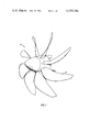
- FIG. 1 is a perspective view of a prop-fan propulsor
- FIG. 2 is a graphic view of the blade with an unswept planform and the waveforms used to chart the Mach surfaces with a plot of the calculated leading and trailing Mach surfaces;
- FIG. 3 is similar to FIG. 2 with additional sweep showing an intermediate step to achieve the desired planform
- FIG. 4 is similar to FIGS. 2 and 3 with still additional sweep showing the desired planform.
- the prop-fan generally illustrated by reference numeral 10 comprises a plurality of variable pitch blades 12 rotatably supported in a suitable hub 14 for conventional pitch change movements.
- the invention is primarily concerned with the planform of the blades, the details of the blade rotating and pitch changing movement are omitted herein for the sake of convenience and simplicity.
- shock waves contain high levels of high frequency noise which is objectionable for blades operating at transonic and supersonic helical Mach numbers.
- the objectives are to design the propulsor so that it not only is efficient from a fuel economy standpoint, and has the necessary structural integrity, it must meet Federal noise regulations and it should be as noise free as possible.
- FIG. 2 shows an example of calculated leading and trailing Mach surfaces or bow wave and trailing wave respectively, (illustrated by the curved lines 20 & 22 respectively) generated by blade 12a (corresponding to blade 12 of FIG. 1) with an unswept planform.
- the leading Mach surface 20 was constructed by calculating noise pressure waveforms illustrated by reference numerals 26A, 26B and 26C at several radial stations (1.1, 0.8 and 0.5) and then connecting the points locating the leading edge pressure pulses.
- the peak A of waveform 26C at the 0.5 station reflects the wave pattern at the leading edge plotted as point B (r/R is the nondimensional radii terms where r is the actual radius and R is the total radius).
- the peak C reflects the wave pattern at the trailing edge and corresponds to plotted point D.
- the other points E, F, G and H are plotted for waveforms 26B and 26A. (Obviously as many points can be plotted as may be desired.)
- the points are connected to produce the Mach surfaces 20 and 22, as shown.
- This planform is an actual test model blade that has the calculated waveforms as shown, noting that the positive peaks are spiked which is, as is well known, a noise signal.
- the strong positive pressure peaks occur because the blade edges are more or less aligned with the Mach surfaces. This can be improved upon by sweeping the planform edges behind their corresponding Mach surfaces as shown in FIGS. 3 and 4.
- blade 12B shows a planform with enough sweep to move the leading edge 30 behind its Mach surface 32.
- the leading positive pulse is eliminated reflecting a consequential reduction in noise.
- FIG. 4 shows a more extreme sweep of blade 12C where both blade edges fall behind their corresponding Mach surfaces.
- the reduction in leading and trailing edge pulse in the noise waveform and the significant smoothing out of the positive spikes as shown in FIG. 4 indicates the reduction in the noise generated by the prop-fan blades. Since the Mach surface locations change when the planform is changed, the noise reduction planform of this invention is the result of a trail and error process accomplished by use of the theory described in AIAA Paper No. 76-565 or by actual pressure wave measurements.
Abstract
Description
Claims (1)
Priority Applications (1)
| Application Number | Priority Date | Filing Date | Title |
|---|---|---|---|
| US06/232,599 US4358246A (en) | 1979-07-16 | 1981-10-13 | Noise reduction means for prop-fan and the construction thereof |
Applications Claiming Priority (2)
| Application Number | Priority Date | Filing Date | Title |
|---|---|---|---|
| US06/058,046 US4370097A (en) | 1979-07-16 | 1979-07-16 | Noise reduction means for prop-fan |
| US06/232,599 US4358246A (en) | 1979-07-16 | 1981-10-13 | Noise reduction means for prop-fan and the construction thereof |
Related Parent Applications (1)
| Application Number | Title | Priority Date | Filing Date |
|---|---|---|---|
| US06/058,046 Division US4370097A (en) | 1979-07-16 | 1979-07-16 | Noise reduction means for prop-fan |
Publications (1)
| Publication Number | Publication Date |
|---|---|
| US4358246A true US4358246A (en) | 1982-11-09 |
Family
ID=26737167
Family Applications (1)
| Application Number | Title | Priority Date | Filing Date |
|---|---|---|---|
| US06/232,599 Expired - Lifetime US4358246A (en) | 1979-07-16 | 1981-10-13 | Noise reduction means for prop-fan and the construction thereof |
Country Status (1)
| Country | Link |
|---|---|
| US (1) | US4358246A (en) |
Cited By (25)
| Publication number | Priority date | Publication date | Assignee | Title |
|---|---|---|---|---|
| FR2576872A1 (en) * | 1985-02-07 | 1986-08-08 | United Technologies Corp | PROPELLER WITH LEAF END ARM WITH IMPROVED STABILITY |
| US4730985A (en) * | 1985-02-07 | 1988-03-15 | United Technologies Corporation | Prop-fan with improved stability |
| EP0266298A2 (en) * | 1986-10-28 | 1988-05-04 | United Technologies Corporation | Reduced loss swept supersonic fan blade |
| US4784575A (en) * | 1986-11-19 | 1988-11-15 | General Electric Company | Counterrotating aircraft propulsor blades |
| US4790724A (en) * | 1986-10-24 | 1988-12-13 | Office National D'etudes Et De Recherche Aerospatiales | Aerial propellors more especially for aircraft propulsive units |
| US4930990A (en) * | 1989-09-15 | 1990-06-05 | Siemens-Bendix Automotive Electronics Limited | Quiet clutch fan blade |
| US4971641A (en) * | 1988-11-14 | 1990-11-20 | General Electric Company | Method of making counterrotating aircraft propeller blades |
| US5192193A (en) * | 1991-06-21 | 1993-03-09 | Ingersoll-Dresser Pump Company | Impeller for centrifugal pumps |
| USRE34207E (en) * | 1986-11-19 | 1993-03-30 | General Electric Company | Counterrotating aircraft propulsor blades |
| US5642985A (en) * | 1995-11-17 | 1997-07-01 | United Technologies Corporation | Swept turbomachinery blade |
| EP0801230A2 (en) * | 1996-04-09 | 1997-10-15 | ROLLS-ROYCE plc | Swept fan blade |
| US6071077A (en) * | 1996-04-09 | 2000-06-06 | Rolls-Royce Plc | Swept fan blade |
| US20060228206A1 (en) * | 2005-04-07 | 2006-10-12 | General Electric Company | Low solidity turbofan |
| US20070243068A1 (en) * | 2005-04-07 | 2007-10-18 | General Electric Company | Tip cambered swept blade |
| US20080014091A1 (en) * | 2004-10-05 | 2008-01-17 | Honeywell International, Inc. | Frequency tailored thickness blade for a turbomachine wheel |
| US20080131272A1 (en) * | 2006-11-30 | 2008-06-05 | General Electric Company | Advanced booster system |
| US20080131271A1 (en) * | 2006-11-30 | 2008-06-05 | General Electric Company | Advanced booster stator vane |
| US20090297357A1 (en) * | 2008-05-30 | 2009-12-03 | Amr Ali | Propfan assembly |
| US20150017012A1 (en) * | 2012-01-30 | 2015-01-15 | Snecma | Turbojet fan blade |
| US8998582B2 (en) | 2010-11-15 | 2015-04-07 | Sundyne, Llc | Flow vector control for high speed centrifugal pumps |
| US9051044B2 (en) | 2010-05-18 | 2015-06-09 | Hamilton Sundstrand Corporation | Counter-rotating open-rotor (CROR) |
| US9568009B2 (en) | 2013-03-11 | 2017-02-14 | Rolls-Royce Corporation | Gas turbine engine flow path geometry |
| CN107829958A (en) * | 2016-09-15 | 2018-03-23 | 通用电气公司 | Aircraft fan with lower part span solidity |
| US10814966B2 (en) | 2015-05-25 | 2020-10-27 | Dotterel Technologies Limited | Shroud for an aircraft |
| US11097828B2 (en) | 2017-07-24 | 2021-08-24 | Dotterel Technologies Limited | Shroud |
Citations (11)
| Publication number | Priority date | Publication date | Assignee | Title |
|---|---|---|---|---|
| FR684161A (en) * | 1929-01-04 | 1930-06-23 | Belge Const Aeronautiques | Propeller |
| US1991095A (en) * | 1933-10-14 | 1935-02-12 | Westinghouse Electric & Mfg Co | Silent pressure fan |
| CH184376A (en) * | 1934-09-07 | 1936-05-31 | Ignaz Storek Stahlhuette Eisen | Impeller for high-speed centrifugal machines. |
| US2269287A (en) * | 1939-11-29 | 1942-01-06 | Wilmer S Roberts | Fan |
| US3972646A (en) * | 1974-04-12 | 1976-08-03 | Bolt Beranek And Newman, Inc. | Propeller blade structures and methods particularly adapted for marine ducted reversible thrusters and the like for minimizing cavitation and related noise |
| US3989406A (en) * | 1974-11-26 | 1976-11-02 | Bolt Beranek And Newman, Inc. | Method of and apparatus for preventing leading edge shocks and shock-related noise in transonic and supersonic rotor blades and the like |
| US3995970A (en) * | 1974-09-10 | 1976-12-07 | Mitsubishi Jukogyo Kabushiki Kaisha | Axial-flow fan |
| US4012172A (en) * | 1975-09-10 | 1977-03-15 | Avco Corporation | Low noise blades for axial flow compressors |
| US4168939A (en) * | 1977-09-08 | 1979-09-25 | The United States Of America As Represented By The Administrator Of The National Aeronautics And Space Administration | Acoustically swept rotor |
| US4171183A (en) * | 1976-09-24 | 1979-10-16 | United Technologies Corporation | Multi-bladed, high speed prop-fan |
| US4248572A (en) * | 1978-12-11 | 1981-02-03 | United Technologies Corporation | Helicopter blade |
-
1981
- 1981-10-13 US US06/232,599 patent/US4358246A/en not_active Expired - Lifetime
Patent Citations (11)
| Publication number | Priority date | Publication date | Assignee | Title |
|---|---|---|---|---|
| FR684161A (en) * | 1929-01-04 | 1930-06-23 | Belge Const Aeronautiques | Propeller |
| US1991095A (en) * | 1933-10-14 | 1935-02-12 | Westinghouse Electric & Mfg Co | Silent pressure fan |
| CH184376A (en) * | 1934-09-07 | 1936-05-31 | Ignaz Storek Stahlhuette Eisen | Impeller for high-speed centrifugal machines. |
| US2269287A (en) * | 1939-11-29 | 1942-01-06 | Wilmer S Roberts | Fan |
| US3972646A (en) * | 1974-04-12 | 1976-08-03 | Bolt Beranek And Newman, Inc. | Propeller blade structures and methods particularly adapted for marine ducted reversible thrusters and the like for minimizing cavitation and related noise |
| US3995970A (en) * | 1974-09-10 | 1976-12-07 | Mitsubishi Jukogyo Kabushiki Kaisha | Axial-flow fan |
| US3989406A (en) * | 1974-11-26 | 1976-11-02 | Bolt Beranek And Newman, Inc. | Method of and apparatus for preventing leading edge shocks and shock-related noise in transonic and supersonic rotor blades and the like |
| US4012172A (en) * | 1975-09-10 | 1977-03-15 | Avco Corporation | Low noise blades for axial flow compressors |
| US4171183A (en) * | 1976-09-24 | 1979-10-16 | United Technologies Corporation | Multi-bladed, high speed prop-fan |
| US4168939A (en) * | 1977-09-08 | 1979-09-25 | The United States Of America As Represented By The Administrator Of The National Aeronautics And Space Administration | Acoustically swept rotor |
| US4248572A (en) * | 1978-12-11 | 1981-02-03 | United Technologies Corporation | Helicopter blade |
Non-Patent Citations (2)
| Title |
|---|
| AIAA Paper No. 76-565, 3rd AIAA Aero-Acoustics Conference, Palo, Cal., Jul. 2-23, 1976. * |
| Mechanix Illustrated; Apr. 1978; vol. 74, No. 599, p. 38. * |
Cited By (42)
| Publication number | Priority date | Publication date | Assignee | Title |
|---|---|---|---|---|
| US4730985A (en) * | 1985-02-07 | 1988-03-15 | United Technologies Corporation | Prop-fan with improved stability |
| FR2576872A1 (en) * | 1985-02-07 | 1986-08-08 | United Technologies Corp | PROPELLER WITH LEAF END ARM WITH IMPROVED STABILITY |
| US4790724A (en) * | 1986-10-24 | 1988-12-13 | Office National D'etudes Et De Recherche Aerospatiales | Aerial propellors more especially for aircraft propulsive units |
| AU601502B2 (en) * | 1986-10-28 | 1990-09-13 | United Technologies Corporation | Reduced loss swept supersonic fan blade |
| EP0266298A2 (en) * | 1986-10-28 | 1988-05-04 | United Technologies Corporation | Reduced loss swept supersonic fan blade |
| EP0266298A3 (en) * | 1986-10-28 | 1989-05-10 | United Technologies Corporation | Reduced loss swept supersonic fan blade |
| USRE34207E (en) * | 1986-11-19 | 1993-03-30 | General Electric Company | Counterrotating aircraft propulsor blades |
| US4784575A (en) * | 1986-11-19 | 1988-11-15 | General Electric Company | Counterrotating aircraft propulsor blades |
| US4971641A (en) * | 1988-11-14 | 1990-11-20 | General Electric Company | Method of making counterrotating aircraft propeller blades |
| US4930990A (en) * | 1989-09-15 | 1990-06-05 | Siemens-Bendix Automotive Electronics Limited | Quiet clutch fan blade |
| US5192193A (en) * | 1991-06-21 | 1993-03-09 | Ingersoll-Dresser Pump Company | Impeller for centrifugal pumps |
| USRE38040E1 (en) | 1995-11-17 | 2003-03-18 | United Technologies Corporation | Swept turbomachinery blade |
| US5642985A (en) * | 1995-11-17 | 1997-07-01 | United Technologies Corporation | Swept turbomachinery blade |
| USRE43710E1 (en) | 1995-11-17 | 2012-10-02 | United Technologies Corp. | Swept turbomachinery blade |
| USRE45689E1 (en) | 1995-11-17 | 2015-09-29 | United Technologies Corporation | Swept turbomachinery blade |
| EP0801230A2 (en) * | 1996-04-09 | 1997-10-15 | ROLLS-ROYCE plc | Swept fan blade |
| EP0801230A3 (en) * | 1996-04-09 | 1998-08-12 | ROLLS-ROYCE plc | Swept fan blade |
| US6071077A (en) * | 1996-04-09 | 2000-06-06 | Rolls-Royce Plc | Swept fan blade |
| US20080014091A1 (en) * | 2004-10-05 | 2008-01-17 | Honeywell International, Inc. | Frequency tailored thickness blade for a turbomachine wheel |
| US20060228206A1 (en) * | 2005-04-07 | 2006-10-12 | General Electric Company | Low solidity turbofan |
| US20070243068A1 (en) * | 2005-04-07 | 2007-10-18 | General Electric Company | Tip cambered swept blade |
| US7374403B2 (en) | 2005-04-07 | 2008-05-20 | General Electric Company | Low solidity turbofan |
| US7476086B2 (en) | 2005-04-07 | 2009-01-13 | General Electric Company | Tip cambered swept blade |
| US20080131272A1 (en) * | 2006-11-30 | 2008-06-05 | General Electric Company | Advanced booster system |
| US20080131271A1 (en) * | 2006-11-30 | 2008-06-05 | General Electric Company | Advanced booster stator vane |
| US8087884B2 (en) * | 2006-11-30 | 2012-01-03 | General Electric Company | Advanced booster stator vane |
| US8292574B2 (en) * | 2006-11-30 | 2012-10-23 | General Electric Company | Advanced booster system |
| US8517677B2 (en) | 2006-11-30 | 2013-08-27 | General Electric Company | Advanced booster system |
| US8425191B2 (en) | 2008-05-30 | 2013-04-23 | United Technologies Corporation | Propfan assembly |
| US20090297357A1 (en) * | 2008-05-30 | 2009-12-03 | Amr Ali | Propfan assembly |
| US9718536B2 (en) | 2010-05-18 | 2017-08-01 | Hamilton Sundstrand Corporation | Counter-rotating open-rotor (CROR) |
| US9051044B2 (en) | 2010-05-18 | 2015-06-09 | Hamilton Sundstrand Corporation | Counter-rotating open-rotor (CROR) |
| US8998582B2 (en) | 2010-11-15 | 2015-04-07 | Sundyne, Llc | Flow vector control for high speed centrifugal pumps |
| US9695695B2 (en) * | 2012-01-30 | 2017-07-04 | Snecma | Turbojet fan blade |
| US20150017012A1 (en) * | 2012-01-30 | 2015-01-15 | Snecma | Turbojet fan blade |
| US9568009B2 (en) | 2013-03-11 | 2017-02-14 | Rolls-Royce Corporation | Gas turbine engine flow path geometry |
| US10814966B2 (en) | 2015-05-25 | 2020-10-27 | Dotterel Technologies Limited | Shroud for an aircraft |
| CN107829958A (en) * | 2016-09-15 | 2018-03-23 | 通用电气公司 | Aircraft fan with lower part span solidity |
| US10458426B2 (en) | 2016-09-15 | 2019-10-29 | General Electric Company | Aircraft fan with low part-span solidity |
| CN107829958B (en) * | 2016-09-15 | 2021-07-09 | 通用电气公司 | Aircraft fan with low part span solidity |
| US11300136B2 (en) | 2016-09-15 | 2022-04-12 | General Electric Company | Aircraft fan with low part-span solidity |
| US11097828B2 (en) | 2017-07-24 | 2021-08-24 | Dotterel Technologies Limited | Shroud |
Similar Documents
| Publication | Publication Date | Title |
|---|---|---|
| US4358246A (en) | Noise reduction means for prop-fan and the construction thereof | |
| US4370097A (en) | Noise reduction means for prop-fan | |
| Hanson | Influence of propeller design parameters on far-field harmonic noise in forward flight | |
| US3989406A (en) | Method of and apparatus for preventing leading edge shocks and shock-related noise in transonic and supersonic rotor blades and the like | |
| Parry et al. | Asymptotic theory of propeller noise. I-Subsonic single-rotation propeller | |
| Yin et al. | Helicopter Main‐Rotor/Tail‐Rotor Interaction | |
| Rohrbach et al. | Evaluation of wind tunnel performance testings of an advanced 45 deg swept 8-bladed propeller at Mach numbers from 0.45 to 0.85 | |
| US4969800A (en) | Open rotor blading | |
| Mitchell et al. | Summary and recent results from the NASA advanced high-speed propeller research program | |
| Dugan et al. | The NASA high-speed turboprop program | |
| Mehmed et al. | Bending-torsion flutter of a highly swept advanced turboprop | |
| Hayden et al. | Analysis and design of a high tip speed, low noise aircraft fan incorporating swept leading edge rotor and stator blades | |
| Dugan et al. | Prop-Fan propulsion-its status and potential | |
| Nakamura | Prediction of blade-vortex interaction noise from measured blade pressure | |
| Dittmar | Some design philosophy for reducing the community noise of advanced counter-rotation propellers | |
| METZGER et al. | Aeroacoustic design of the Prop Fan | |
| Bocci | A new series of aerofoil sections suitable for aircraft propellers | |
| Rand et al. | Efficient method for calculating the axial velocities induced along rotating blades by trailing helical vortices | |
| BOUSQUET | Theoretical and experimental analysis of highspeed propeller aerodynamics | |
| Gounet et al. | Prediction of propfan noise by a frequency-domain scheme | |
| MIXSON et al. | Characteristics of propeller noise on an aircraft fuselage related to interior noise transmission | |
| Dittmar | Cruise noise of counterrotation propeller at angle of attack in wind tunnel | |
| Dunn et al. | High-speed propeller noise prediction-a multidisciplinary approach | |
| Dittmar et al. | A shock wave approach to the noise of supersonic propellers | |
| Mosher | Acoustics of rotors utilizing circulation control |
Legal Events
| Date | Code | Title | Description |
|---|---|---|---|
| STCF | Information on status: patent grant |
Free format text: PATENTED CASE |
|
| MAFP | Maintenance fee payment |
Free format text: PAYMENT OF MAINTENANCE FEE, 4TH YEAR, PL 96-517 (ORIGINAL EVENT CODE: M170); ENTITY STATUS OF PATENT OWNER: LARGE ENTITY Year of fee payment: 4 |
|
| MAFP | Maintenance fee payment |
Free format text: PAYMENT OF MAINTENANCE FEE, 8TH YEAR, PL 96-517 (ORIGINAL EVENT CODE: M171); ENTITY STATUS OF PATENT OWNER: LARGE ENTITY Year of fee payment: 8 |
|
| MAFP | Maintenance fee payment |
Free format text: PAYMENT OF MAINTENANCE FEE, 12TH YEAR, LARGE ENTITY (ORIGINAL EVENT CODE: M185); ENTITY STATUS OF PATENT OWNER: LARGE ENTITY Year of fee payment: 12 |
|
| FEPP | Fee payment procedure |
Free format text: PAYOR NUMBER ASSIGNED (ORIGINAL EVENT CODE: ASPN); ENTITY STATUS OF PATENT OWNER: LARGE ENTITY |