US4355731A - Egg supporting tray - Google Patents
Egg supporting tray Download PDFInfo
- Publication number
- US4355731A US4355731A US06/243,680 US24368081A US4355731A US 4355731 A US4355731 A US 4355731A US 24368081 A US24368081 A US 24368081A US 4355731 A US4355731 A US 4355731A
- Authority
- US
- United States
- Prior art keywords
- egg
- posts
- plane
- supporting tray
- tray
- Prior art date
- Legal status (The legal status is an assumption and is not a legal conclusion. Google has not performed a legal analysis and makes no representation as to the accuracy of the status listed.)
- Expired - Fee Related
Links
- 235000013601 eggs Nutrition 0.000 abstract description 112
- XLYOFNOQVPJJNP-UHFFFAOYSA-N water Substances O XLYOFNOQVPJJNP-UHFFFAOYSA-N 0.000 abstract description 6
- 238000001035 drying Methods 0.000 abstract description 3
- 238000005406 washing Methods 0.000 abstract description 3
- 239000004698 Polyethylene Substances 0.000 description 2
- 239000000463 material Substances 0.000 description 2
- 238000000034 method Methods 0.000 description 2
- 230000002093 peripheral effect Effects 0.000 description 2
- -1 polyethylene Polymers 0.000 description 2
- 229920000573 polyethylene Polymers 0.000 description 2
- 238000005336 cracking Methods 0.000 description 1
- 238000004519 manufacturing process Methods 0.000 description 1
- 238000012986 modification Methods 0.000 description 1
- 230000004048 modification Effects 0.000 description 1
- 230000000717 retained effect Effects 0.000 description 1
- 238000007666 vacuum forming Methods 0.000 description 1
Images


Classifications
-
- B—PERFORMING OPERATIONS; TRANSPORTING
- B65—CONVEYING; PACKING; STORING; HANDLING THIN OR FILAMENTARY MATERIAL
- B65D—CONTAINERS FOR STORAGE OR TRANSPORT OF ARTICLES OR MATERIALS, e.g. BAGS, BARRELS, BOTTLES, BOXES, CANS, CARTONS, CRATES, DRUMS, JARS, TANKS, HOPPERS, FORWARDING CONTAINERS; ACCESSORIES, CLOSURES, OR FITTINGS THEREFOR; PACKAGING ELEMENTS; PACKAGES
- B65D85/00—Containers, packaging elements or packages, specially adapted for particular articles or materials
- B65D85/30—Containers, packaging elements or packages, specially adapted for particular articles or materials for articles particularly sensitive to damage by shock or pressure
- B65D85/32—Containers, packaging elements or packages, specially adapted for particular articles or materials for articles particularly sensitive to damage by shock or pressure for eggs
- B65D85/322—Trays made of pressed material, e.g. paper pulp
Definitions
- This invention relates to an egg supporting tray.
- this invention relates to an egg supporting tray which will accommodate different size eggs.
- this invention relates to an egg supporting tray which provides minimum contact between the eggs and the tray when the eggs are small and which can also be utilized to support large eggs.
- Eggs are relatively fragile articles and care must be excercised in the collecting, processing, and other handling in order to avoid damaging or breaking the eggs.
- a large variety of egg supporting trays for handling the eggs are known.
- Egg supporting trays are commonly filled with eggs and stacked in crates. If the eggs do not fit properly into the egg pockets of the egg supporting trays (too high) breakage may occur when the trays are stacked. Many trays are thus designed for only a particular size egg. Use of different size trays presents economic disadvantages, impacts manufacturing facilities, and presents difficulties in shipping eggs.
- an improved egg supporting tray in which the egg pockets have a plurality of ridges which support small eggs and a plurality of concave surfaces which support large eggs.
- the plurality of ridges are located in the lower part of the egg pocket while the plurality of concave surfaces are located in an upper part of the egg pocket.
- Small eggs rest on the ridges and thus the advantages provided by the minimum contact of such ridges are provided for small eggs. Larger eggs rest on the concave surfaces.
- the contact area is increased with respect to the contact area on small eggs but the same size egg supporting tray can still be utilized.
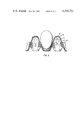
- FIG. 1 is a pictorial view illustrating the egg supporting tray of the present invention
- FIG. 2 is a plan view of a portion of the egg supporting tray illustrated in FIG. 1;
- FIG. 3 is a cross sectional view, taken along line A--A of FIG. 2 of an egg pocket containing a large egg;
- FIG. 4 is a cross sectional view, taken along line A--A of FIG. 2, of an egg pocket containing a small egg.
- an egg supporting tray 10 which is formed from a sheet of stiff material.
- the egg supporting tray 10 has a generally rectangular periphery which is formed from the edges of the sheet from which the tray 10 is formed.
- a plane which contains the peripheral edges of the tray 10 will be utilized hereinafter as a reference plane for the description of the tray 10. Such a plane will be referred to hereinafter as the "plane of the periphery”.
- the tray 10 has a plurality of egg pockets 11. Each of the egg pockets 11 extends downwards below the plane of the periphery. As is shown in FIG. 2, each of the egg pockets 11 is preferably provided with a drainage hole 12 in the bottom thereof. As will more paticularly be pointed out hereinafter, it may be desirable to delete the drainage hole 12 under certain circumstances.
- the egg pockets 11 are arranged in six substantially parallel rows running in the direction of the arrow 13 and by five substantially parallel columns transverse to the rows, running in the direction of the arrow 14.
- the first, second, fifth and sixth rows of the egg pockets 11 each begin with and end with a half egg pocket 16 which also extends below the plane of the periphery.
- the walls of the egg pockets 11 are formed in part by a plurality of tapered (preferably substantially frustoconical) posts, such as the posts 17, which each extend upward above the plane of the periphery to an apex and downward below the plane of the periphery to a base.
- the apexes of the posts 17 are located in a plane which will be referred to hereinafter as the "first" plane.
- the bases are located in a plane which will be referred to hereinafter as the "second" plane.
- Four of the posts 17 are spaced equidistantly about each of the egg pockets 11.
- the posts 17 are arranged in seven substantially parallel rows running in the direction of arrow 13 and are also arranged in six substantially parallel columns running in the direction of arrow 14.
- the first and seventh rows of the posts 17 are half posts, such as 17', which are positioned along the opposite peripheral sides of the tray 10.
- the half posts 17' are also hollow and are tapered on one side only which faces the egg pockets 11 adjacent thereto
- the knobs 18 are each surrounded by a shoulder 19 which together with the knob 18 has a transverse area larger than the opening 12. While the half posts 17' are not provided with a knob 18 and shoulder 19, it will be noted that preferably at least two of the posts 17, which are spaced about each of the egg pockets 11, terminate with a knob 18 and shoulder 19.
- a second portion of the walls of the egg pockets 11 are formed by the plurality of ribs 22.
- the tops of the ribs 22 are substantially in the plane of the periphery.
- Each of the ribs 22 extends downwardly below the plane of the periphery between a pair of the posts 17 to the base of the posts 17 (the second plane).
- the ribs 22 are preferably tapered with respect to the center of the egg pocket 11, i.e., the ribs 22 are wider at the bottom near the base of the posts 17 than at the top near the plane of the periphery.
- a concave surface 20 is formed on each surface of the posts 17 and 17' which form a part of the egg pockets 11 with the direction of concavity being towards the inside of the posts 17.
- the concave surface 20 extends along the surface of the posts 17 and 17' from a point near the apex of the posts 17 and 17' downward to a point close to but below the plane of the periphery.
- the curvature and width of the concave surface 20 is preferably such as will allow a large egg to contact substantially the entire concave surface 20.
- Four concave surfaces are present in each egg pocket 11.
- An elongated ridge 21 projects from the surface of each of the posts 17 and half posts 17' which form a part of the egg pockets 11.
- Each elongated ridge 21 extends along the surface of the posts 17 and half posts 17' from a point, adjacent to the point at which the concave surface 20 terminates below the plane of the periphery, downward to a point substantially half way between the bottom of the egg pockets 11 (second plane) and the plane of the periphery. It is noted that the ridges 21 could extend substantially to the bottom of the egg pocket 11 (second plane) if desired.
- Any suitable width for the ridges 21 may be utilized but preferably the width is such that, if a small egg is supported entirely by the four of the ridges 21 in the egg pocket, the pressure on the egg will not be such as to cause breakage and leaking.
- the ridges 21 provide essentially only 4 point contact between the egg and the egg supporting tray thus providing a minimum region for water to be retained at the points of contact and water spotting is essentially completely eliminated. Also washing of the small eggs is facilitated due to the improved circulation of water around the eggs and drying is facilitated by the improved circulation of air.
- the contact area is increased, as is illustrated in FIG. 3, but the large egg is seated low enough in the egg pocket to prevent breakage when trays are stacked.
- the larger area of contact is less desirable then the four point contact provided by the ribs 21 but it is more desirable to increase the contact area than to incur the expenses which would be involved in increasing the size of the egg supporting tray to accommodate larger eggs without breakage.
- the egg supporting tray of the present invention may be utilized to support smaller eggs with the advantages of four ridge support and may also be utilized to support larger eggs without changing the size of the egg supporting tray.
- each egg pocket 11 preferably has a hole 12 in the bottom thereof.
- each egg pocket 11 preferably has a hole 12 in the bottom thereof.
- cracking and breakage of the handled eggs Cracked eggs which cannot be sold in regular commerce for future use are customarily shipped to dehydrating or other processing plants for immediate use. If leaking eggs are being shipped, it is desirable to close the bottom of the egg pockets 11.
- the thus closed bottoms of the egg pockets 11 are preferably concave in the general shape of the end of an egg.
- knobs 18 on the tapered posts 17 should register with and extend into the drainage holes 12 of the tray above when the trays are stacked so as to provide maximum support for the stacked trays.
- the upper tray is rotated 90 degrees with respect to the lower tray thus bringing the knobs 18 on the five posts 17 in each column of the post on the lower tray into register with the 5 drainage holes 12 in each row of egg pockets 11 in the upper tray.
- the upper ends of the eggs are positioned within the hollow downward facing interior of the posts 17 on the upper tray and the lower ends of the eggs are positioned in the egg pocket 11 and the four posts adjacent thereto in the lower tray.
- the hole 12 is not essential. If the hole 12 is not present, it may be desirable to delete the knob 18 to provide a larger surface on which the egg trays may be stacked.
- Each tray is formed to hold a definite number of eggs, for example 30, and the periphery or rim of the tray can be formed of cutout portions 23 on two sides thereof.
- the cut out portions 23 serve as finger openings, allowing each tray to be grasped on its edges for convenient handling thereof.
- the ridges 25 help to keep stacked egg supporting trays separated which further facilitates handling of the egg supporting trays.
- the top surface of the knobs 18 may be flat, as illustrated in FIG. 1, or may be concave. The use of a concave top surface may prevent a small egg from contacting the knob 18 projecting through a hole 12.
- the egg supporting tray 10 can be fabricated from any suitable material.
- the egg supporting tray is formed from polyethylene.
- the egg supporting tray can be fabricated by any suitable means.
- the known process of vacuum forming is preferably utilized to form the tray 10 from polyethylene sheet.
Abstract
Description
Claims (6)
Priority Applications (2)
| Application Number | Priority Date | Filing Date | Title |
|---|---|---|---|
| US06/243,680 US4355731A (en) | 1981-03-16 | 1981-03-16 | Egg supporting tray |
| CA000397338A CA1171821A (en) | 1981-03-16 | 1982-03-01 | Egg supporting tray |
Applications Claiming Priority (1)
| Application Number | Priority Date | Filing Date | Title |
|---|---|---|---|
| US06/243,680 US4355731A (en) | 1981-03-16 | 1981-03-16 | Egg supporting tray |
Publications (1)
| Publication Number | Publication Date |
|---|---|
| US4355731A true US4355731A (en) | 1982-10-26 |
Family
ID=22919690
Family Applications (1)
| Application Number | Title | Priority Date | Filing Date |
|---|---|---|---|
| US06/243,680 Expired - Fee Related US4355731A (en) | 1981-03-16 | 1981-03-16 | Egg supporting tray |
Country Status (2)
| Country | Link |
|---|---|
| US (1) | US4355731A (en) |
| CA (1) | CA1171821A (en) |
Cited By (18)
| Publication number | Priority date | Publication date | Assignee | Title |
|---|---|---|---|---|
| GB2203408A (en) * | 1987-03-24 | 1988-10-19 | Boxmore Limited | Egg trays |
| WO1995003236A1 (en) * | 1993-07-22 | 1995-02-02 | Brødrene Hartmann A/S | Egg packaging set |
| WO1995008495A1 (en) * | 1993-09-24 | 1995-03-30 | Brødrene Hartmann A/S | Rectangular egg tray |
| US5816406A (en) * | 1996-06-25 | 1998-10-06 | Jupille Design Incorporated | Stacking trays |
| US5827068A (en) * | 1996-12-31 | 1998-10-27 | Michelson Packaging Co. | Fruit packaging tray usable with a denesting apparatus |
| US6012583A (en) * | 1998-09-15 | 2000-01-11 | Tekni-Plex, Inc. | Egg carton |
| US6401434B1 (en) | 1999-12-02 | 2002-06-11 | Michelsen Packaging Company | Method and apparatus for loading filled fruit packing trays |
| US6419089B1 (en) * | 1997-08-15 | 2002-07-16 | Brodrene Hartmann A/S | Egg tray |
| NL1021727C2 (en) * | 2002-10-23 | 2004-04-26 | Huhtamaki Nederland B V | Egg tray. |
| US20040104143A1 (en) * | 2002-12-02 | 2004-06-03 | Boche Jurgen Hans | Reusable packaging system |
| US6769862B1 (en) | 2002-12-03 | 2004-08-03 | Jeffrey B. Kuhl | Apparatus and method for placing horizontally oriented flats into vertically extending stacks thereof |
| EP1911690A1 (en) * | 2006-10-11 | 2008-04-16 | Ditta Barosi, Aldo | Egg tray |
| US20100040744A1 (en) * | 2008-08-13 | 2010-02-18 | Joong-Min Park | Egg tray and fixer and method of processing eggs using the same |
| US20150079336A1 (en) * | 2013-09-17 | 2015-03-19 | Applied Materials, Inc. | Geometries and patterns for surface texturing to increase deposition retention |
| USD793252S1 (en) * | 2013-10-15 | 2017-08-01 | Parmalat Canada Inc. | Tray for jugs |
| USD842128S1 (en) * | 2017-03-27 | 2019-03-05 | Giordano Poultry Plast S.P.A. | Egg tray |
| USD894758S1 (en) * | 2018-08-24 | 2020-09-01 | Tekni-Plex, Inc. | Egg carton with bubble cell pockets |
| USD966904S1 (en) | 2018-08-24 | 2022-10-18 | Tekni-Plex, Inc. | Egg carton with bubble cell pockets |
Citations (5)
| Publication number | Priority date | Publication date | Assignee | Title |
|---|---|---|---|---|
| US2662659A (en) * | 1951-02-23 | 1953-12-15 | Putnam William Dudley | Packing device |
| US3360150A (en) * | 1963-03-22 | 1967-12-26 | Phillips Petroleum Co | Packing or supporting tray |
| US3451577A (en) * | 1967-01-16 | 1969-06-24 | Food Systems Inc | Egg tray construction |
| US3771712A (en) * | 1971-03-02 | 1973-11-13 | Autobars Vendabeka Ltd | Boxes or packs for packaging eggs; fruit or other articles |
| US3877599A (en) * | 1973-08-03 | 1975-04-15 | Multifax Corp | Egg tray |
-
1981
- 1981-03-16 US US06/243,680 patent/US4355731A/en not_active Expired - Fee Related
-
1982
- 1982-03-01 CA CA000397338A patent/CA1171821A/en not_active Expired
Patent Citations (5)
| Publication number | Priority date | Publication date | Assignee | Title |
|---|---|---|---|---|
| US2662659A (en) * | 1951-02-23 | 1953-12-15 | Putnam William Dudley | Packing device |
| US3360150A (en) * | 1963-03-22 | 1967-12-26 | Phillips Petroleum Co | Packing or supporting tray |
| US3451577A (en) * | 1967-01-16 | 1969-06-24 | Food Systems Inc | Egg tray construction |
| US3771712A (en) * | 1971-03-02 | 1973-11-13 | Autobars Vendabeka Ltd | Boxes or packs for packaging eggs; fruit or other articles |
| US3877599A (en) * | 1973-08-03 | 1975-04-15 | Multifax Corp | Egg tray |
Cited By (25)
| Publication number | Priority date | Publication date | Assignee | Title |
|---|---|---|---|---|
| GB2203408B (en) * | 1987-03-24 | 1991-02-27 | Boxmore Limited | Improvements in egg trays |
| GB2203408A (en) * | 1987-03-24 | 1988-10-19 | Boxmore Limited | Egg trays |
| WO1995003236A1 (en) * | 1993-07-22 | 1995-02-02 | Brødrene Hartmann A/S | Egg packaging set |
| WO1995008495A1 (en) * | 1993-09-24 | 1995-03-30 | Brødrene Hartmann A/S | Rectangular egg tray |
| US5816406A (en) * | 1996-06-25 | 1998-10-06 | Jupille Design Incorporated | Stacking trays |
| US5827068A (en) * | 1996-12-31 | 1998-10-27 | Michelson Packaging Co. | Fruit packaging tray usable with a denesting apparatus |
| US6419089B1 (en) * | 1997-08-15 | 2002-07-16 | Brodrene Hartmann A/S | Egg tray |
| US6012583A (en) * | 1998-09-15 | 2000-01-11 | Tekni-Plex, Inc. | Egg carton |
| US6401434B1 (en) | 1999-12-02 | 2002-06-11 | Michelsen Packaging Company | Method and apparatus for loading filled fruit packing trays |
| NL1021727C2 (en) * | 2002-10-23 | 2004-04-26 | Huhtamaki Nederland B V | Egg tray. |
| WO2004037678A1 (en) * | 2002-10-23 | 2004-05-06 | Huhtamaki Nederland B.V. | Egg tray |
| US20040104143A1 (en) * | 2002-12-02 | 2004-06-03 | Boche Jurgen Hans | Reusable packaging system |
| US20060113204A1 (en) * | 2002-12-02 | 2006-06-01 | Boche Jurgen H | Reusable packaging system |
| US7032747B2 (en) * | 2002-12-02 | 2006-04-25 | Hni Technologies Inc. | Reusable packaging system |
| US6769862B1 (en) | 2002-12-03 | 2004-08-03 | Jeffrey B. Kuhl | Apparatus and method for placing horizontally oriented flats into vertically extending stacks thereof |
| EP1911690A1 (en) * | 2006-10-11 | 2008-04-16 | Ditta Barosi, Aldo | Egg tray |
| US20100040744A1 (en) * | 2008-08-13 | 2010-02-18 | Joong-Min Park | Egg tray and fixer and method of processing eggs using the same |
| US8187650B2 (en) * | 2008-08-13 | 2012-05-29 | Joong-Min Park | Egg tray and fixer and method of processing eggs using the same |
| US20150079336A1 (en) * | 2013-09-17 | 2015-03-19 | Applied Materials, Inc. | Geometries and patterns for surface texturing to increase deposition retention |
| US9101954B2 (en) * | 2013-09-17 | 2015-08-11 | Applied Materials, Inc. | Geometries and patterns for surface texturing to increase deposition retention |
| CN105531796A (en) * | 2013-09-17 | 2016-04-27 | 应用材料公司 | Geometries and patterns for surface texturing to increase deposition retention |
| USD793252S1 (en) * | 2013-10-15 | 2017-08-01 | Parmalat Canada Inc. | Tray for jugs |
| USD842128S1 (en) * | 2017-03-27 | 2019-03-05 | Giordano Poultry Plast S.P.A. | Egg tray |
| USD894758S1 (en) * | 2018-08-24 | 2020-09-01 | Tekni-Plex, Inc. | Egg carton with bubble cell pockets |
| USD966904S1 (en) | 2018-08-24 | 2022-10-18 | Tekni-Plex, Inc. | Egg carton with bubble cell pockets |
Also Published As
| Publication number | Publication date |
|---|---|
| CA1171821A (en) | 1984-07-31 |
Similar Documents
| Publication | Publication Date | Title |
|---|---|---|
| US4355731A (en) | Egg supporting tray | |
| US3000528A (en) | Egg tray | |
| US4355485A (en) | Stacking containers | |
| US3360150A (en) | Packing or supporting tray | |
| IE53669B1 (en) | Multi-row egg cartons | |
| US2936922A (en) | Molded pulp packing tray | |
| US2662659A (en) | Packing device | |
| US2974788A (en) | Molded pulp packing for bottles | |
| US4558661A (en) | Egg holding flat | |
| US3695479A (en) | Tray with reinforced article pockets | |
| US3877599A (en) | Egg tray | |
| EP0908401B1 (en) | Egg tray | |
| US3245570A (en) | Packing tray | |
| EP0784577B1 (en) | Stacking tray for bottles | |
| US2233044A (en) | Fragile article support | |
| US2078927A (en) | Molded fiber container for eggs | |
| US3281003A (en) | Packaging tray | |
| US4821901A (en) | Filler flat construction | |
| US3276656A (en) | Package of resilient material for fragile objects | |
| US2924368A (en) | Egg carton | |
| US3031311A (en) | Frozen strawberry package | |
| US2813652A (en) | Tray for fragile articles | |
| US2311473A (en) | Shipping container | |
| US3310218A (en) | Molded pulp produce package | |
| US2872062A (en) | Egg packing flats |
Legal Events
| Date | Code | Title | Description |
|---|---|---|---|
| AS | Assignment |
Owner name: PHILLIPS PETROLEUM COMPANY, A CORP. OF DE Free format text: ASSIGNMENT OF ASSIGNORS INTEREST.;ASSIGNORS:CARROLL JAMES C.;LEFEBVRE PAUL R.;REEL/FRAME:003861/0797;SIGNING DATES FROM 19810528 TO 19810602 |
|
| AS | Assignment |
Owner name: DURACO PRODUCTS, INC., 1109 E. LAKE ST., STREAMWOO Free format text: ASSIGNMENT OF ASSIGNORS INTEREST.;ASSIGNOR:PHILLIPS PETROLEUM COMPANY A DE CORP.;REEL/FRAME:004085/0198 Effective date: 19821210 |
|
| AS | Assignment |
Owner name: DURACO INDUSTRIAL PRODUCTS, INC., 1857 CALVIN DRIV Free format text: ASSIGNMENT OF ASSIGNORS INTEREST.;ASSIGNOR:DURACO PRODUCTS, INC.;REEL/FRAME:004581/0735 Effective date: 19851231 Owner name: DURACO INDUSTRIAL PRODUCTS, INC.,KENTUCKY Free format text: ASSIGNMENT OF ASSIGNORS INTEREST;ASSIGNOR:DURACO PRODUCTS, INC.;REEL/FRAME:004581/0735 Effective date: 19851231 |
|
| FEPP | Fee payment procedure |
Free format text: MAINTENANCE FEE REMINDER MAILED (ORIGINAL EVENT CODE: REM.); ENTITY STATUS OF PATENT OWNER: LARGE ENTITY |
|
| LAPS | Lapse for failure to pay maintenance fees | ||
| STCH | Information on status: patent discontinuation |
Free format text: PATENT EXPIRED DUE TO NONPAYMENT OF MAINTENANCE FEES UNDER 37 CFR 1.362 |
|
| FP | Lapsed due to failure to pay maintenance fee |
Effective date: 19861026 |
|
| AS | Assignment |
Owner name: M&I MARSHALL & ILSLEY BANK, A WI BANKING CORP. Free format text: SECURITY INTEREST;ASSIGNOR:DURACO INDUSTRIAL PRODUCTS, INC.;REEL/FRAME:005338/0153 Effective date: 19900531 Owner name: DURACO INDUSTRIAL PRODUCTS, INC. Free format text: MERGER;ASSIGNOR:DIP ACQUISTION CORP.;REEL/FRAME:005338/0142 Effective date: 19900531 |