US4351782A - Cold-engine starting and operating devices for carburetors - Google Patents
Cold-engine starting and operating devices for carburetors Download PDFInfo
- Publication number
- US4351782A US4351782A US06/225,694 US22569481A US4351782A US 4351782 A US4351782 A US 4351782A US 22569481 A US22569481 A US 22569481A US 4351782 A US4351782 A US 4351782A
- Authority
- US
- United States
- Prior art keywords
- lever
- choke
- throttle valve
- valve
- cam
- Prior art date
- Legal status (The legal status is an assumption and is not a legal conclusion. Google has not performed a legal analysis and makes no representation as to the accuracy of the status listed.)
- Expired - Fee Related
Links
Images

Classifications
-
- F—MECHANICAL ENGINEERING; LIGHTING; HEATING; WEAPONS; BLASTING
- F02—COMBUSTION ENGINES; HOT-GAS OR COMBUSTION-PRODUCT ENGINE PLANTS
- F02M—SUPPLYING COMBUSTION ENGINES IN GENERAL WITH COMBUSTIBLE MIXTURES OR CONSTITUENTS THEREOF
- F02M1/00—Carburettors with means for facilitating engine's starting or its idling below operational temperatures
- F02M1/08—Carburettors with means for facilitating engine's starting or its idling below operational temperatures the means to facilitate starting or idling becoming operative or inoperative automatically
- F02M1/10—Carburettors with means for facilitating engine's starting or its idling below operational temperatures the means to facilitate starting or idling becoming operative or inoperative automatically dependent on engine temperature, e.g. having thermostat
Definitions
- This invention relates to carburetors for internal combustion engines, and more particularly to devices which enable the richness and throughput of the mixture which feeds motor vehicle engines to be increased.
- a throttle valve controls the mixture flow rate to be fed to the engine.
- a choke valve disposed upstream of the choke portion is urged into its closed position by a force which progressively diminishes as the engine temperature increases, starting from a relatively high value to a negligible value which enables the choke valve to be completely opened when thermal equilibrium is reached.
- Means and systems which operate in such a manner as to associate the value of the small opening of the throttle valve with the intensity of the closure force on the choke valve. It is also known to use temperature-sensitive elements subjected to the heating action of a fluid which represents the engine temperature, these elements containing a plastic material of low melting point, the expansion of which enables both the choke valve mechanism and the mechanism which determines the small opening of the throttle valve to be positioned.
- temperature-sensitive elements are able to completely automate the starting devices, i.e. they are automatically put into operation when the engine cools, and are de-activated when the engine heats up.
- the temperature-sensitive element acts on a lever pivoted on the throttle valve spindle.
- the temperature-sensitive element varies the position of the lever, which in its turn varies the intensity of the closure force on the choke valve and the position of the small opening of the throttle valve.
- An arrangement of this type has particular drawbacks, such as not being able to guarantee a reliably valid relationship between the intensity of the closure force on the choke valve and the small opening of the throttle valve, because of the cumulative dimensional tolerance of the members which constitute the device, this cumulative tolerance being inevitable in industrial production. Moreover, by entrusting the positioning of the small opening of the throttle valve to the lever pivoted on the throttle valve spindle, the device becomes especially subject to the dangers deriving from vibration induced by the engine.
- the object of the invention is to provide a cold-engine starting and operating device for carburetors which is of simple construction, is not subject to damage due to vibration induced by the engine, and for which the cumulative dimensional tolerance does not give rise to operational drawbacks.
- the invention consists of an automatic starting device of the aforesaid type, comprising a cam lever pivotally mounted on the central portion of the carburetor body between a main throttle valve of said carburetor and a choke valve mounted eccentrically in the carburetor body tube upstream of the choke portion and pneumatically operated by a pull-rod connected with a member sensitive to the vacuum in the intake manifold downstream from the throttle valve, a mobile element of a temperature-sensitive member which heats up as the engine temperature increases, which mobile element is movable against first elastic means which are adapted to act upon said cam lever, a choke lever fixed on a spindle of said choke valve and a first lever pivotally mounted on a spindle of said throttle valve, said cam lever being pivoted in its medial extent to the carburetor body and biased to rotate by second elastic means as far as limit defined by said mobile element, respective opposite ends of said cam lever having cam contours acting separately against said choke and first levers respectively to compel them to rotate against the action of third and fourth respective
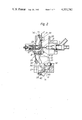
- FIG. 1 shows the device according to the invention in a position which allows the engine to start and operate in its cold state
- FIG. 2 shows the device according to the invention in a second position which allows the engine to operate in its hot state.
- a carburetor for internal combustion engines is constituted, inter alia, by a body tube 1 of known shape which communicates at its top 11 with the air filter and is connected at its bottom 14 to the intake manifold, not shown, located downstream of a throttle valve 13.
- the body tube 1 comprises a choke portion 12 in the form of a venturi into which the conventional main feed circuit, not shown, opens.
- the idling and progression feed circuit, not shown because of conventional type, also opens into the lower part 14 of the body tube.
- the fuel delivery by the main feed circuit depends on the suction which arises in the choke zone 12.
- the suction in the choke zone 12 is not sufficient to draw fuel from the main feed circuit.
- the purpose of the device according to the invention is to obtain a suction in the choke zone 12 which is sufficiently high, even when the throttle valve 13 is in its small opening position, to enable fuel to be delivered by the main circuit.
- the mixture is enriched as required by the engine temperature conditions.
- a choke valve 2 which rotates about an eccentric spindle 21 from the completely closed position (FIG. 1) to the completely open position (FIG. 2).
- the consequence of closing the choke valve 2 is an increase in the suction in the choke zone 12, and thus enrichment of the mixture.
- the consequence of opening the choke valve 2 is the return to a "normal" suction in the choke zone 12, and thus restoration of the normal strength of the mixture delivered by the carburetor.
- the position of the choke valve 2 depends on the position of a cam lever 8. If this is in the position shown in FIG. 1, the pin or appendix on lever 8, on which pin the lower end of a spring 5 is engaged, is at its maximum distance from the eccentric spindle 21. The second end of the spring 5 is engaged on a pin 73 disposed in a choke lever 7. In this manner, the spring 5 closes the choke valve 2, the spindle of which is rigid with the choke lever 7.
- lever cam 8 is as in FIG. 2, a cam 86 disposed at the upper end of the lever 8 urges a roller 74, disposed on the pin 73, upwardly to completely open the choke valve 2.
- Cam lever 8 also acts on a first lever 27, as stated below.
- the position of the lever 8 depends upon the engine temperature, to which an element 3 is sensitive, this being disposed in a cavity 35 through which the engine cooling liquid circulates entering through an inlet 33 and leaving through an outlet 34.
- a housing 32 contains the element 3, which is a thermostatic member of known type in which a substance similar to wax undergoes a large volume change when reversibly passing from one physical state to another, and in particular from the solid state to the liquid state, between two temperature values to which it is subjected which depend upon whether the engine is cold or hot.
- the substance contained in a bulb 30 part of element 3 is only thermally deformable, because of which it is capable of exerting a force much higher than that of a spring 10, so limiting its stroke by means of a point 31 which is inserted into a pusher 23 on which the right hand end of the spring 10 engages.
- the spring 10 is disposed between a support 24 and the pusher 23, and can be preloaded by adjusting an adjustment screw 25.
- the elastic force of the spring 10 is transmitted to the lever 8 because the pusher 23 rests on the right hand surface of an appendix 83 of the lever 8, which extends perpendicularly to the plane of the drawings.
- the appendix 83 is provided with a slot through which the point 31 of the element 3 extends.
- the point 31 is inserted into a bore provided in the pusher 23 to ensure improved rigidity between the two elements. This allows congruent movements of the three elements 31, 83, and 23, which depend only on the temperature to which the element 3 is subjected.
- the lever 8 rotates about a pivot 82. It rotates progressively in an anticlockwise direction urged by a torsion spring 85, when the point 31 moves towards the left following heating of the temperature sensor 3. It rotates progressively in a clockwise direction when the point 31 moves towards the right under the action of the spring 10, as the sensor 3 cools. In the first case the force due to the sensor 3 overcomes the force of the spring 10. In the second case, the movement of the point 31 towards the right enables the spring 10 to act on the lever 8.
- the spring 85 provides an anticlockwise couple which is much less intense than the clockwise couple provided by the spring 10, and besides determining the anticlockwise rotation of the lever 8 due to the movement of the point 31 towards the left, it also keeps the pusher 23 adhering to the appendix 83 of the lever 8 without undergoing any separation due to engine vibration.
- the device which enables the choke valve 2 to be operated comprises the choke lever 7 rigid with the spindle 21, a second lever 6 pivoted on to said spindle 21, and a lever 9 rigid with this latter and the choke lever 7.
- the lever 6 comprises an eyelet 61 in which there engages the right hand end of a pull rod 41 which emerges from a pneumatic device 4, and an appendix 62 perpendicular to the plane of the drawing, which supports a screw 63 the point of which acts on an appendix 91 of the lever 9 perpendicular to the drawing.
- the position of the pull rod 41 corrects the angular position of the choke valve 2 determined by the tension of the spring 5, and thus the position of the pin 81.
- the pull rod 41 is completely displaced to the right as in FIG. 1, the lever 6 is subjected to its maximum anticlockwise movement.
- the screw 63 is in a position withdrawn to the left such that the appendix 91, which comes into contact with the screw 63, can allow maximum anticlockwise movement of the lever 9, which constitutes the anticlockwise limiting element for the members rigid with the spindle 21.
- the lever 6 rotates in a clockwise direction, because of which the screw 63 acting on the appendix 91 of the lever 9 rotates this latter in the same direction against the action of the couple provided by the spring 5, to open the choke valve through a certain extent.
- the point of the screw 63 is positioned in such a manner as to allow closure of the choke valve 2 when the lever 8 is completely rotated clockwise, and to allow immediate action of the pneumatic device once the engine is started, by eliminating any possible slack between the levers 6 and 9.
- the movement of the pull rod towards the left also depends in the present invention on the suction in the intake manifold.
- the suction is low, the pull rod 41 is completely moved to the right; when it is high, the pull rod 41 is completely moved to the left.
- These positions of the pull rod 41 correspond respectively to the positions 2 and 2a of the choke valve 2.
- the lever 8 As its lower end, the lever 8 includes a cam contour 84 which cooperates with a roller 26 in order to position the first lever 27, which is pivotal on the spindle 15 of the throttle valve 13.
- the relative movements are as follows: when the lever 8 rotates anticlockwise, the lever 27 rotates clockwise, urged by a spring 28. In contrast, when the lever 8 rotates clockwise, the lever 27 rotates anticlockwise against the bias of the spring 28 disposed between pins 26 and 92.
- Pin 25 is on lever 27 and journals the roller 26, and pin 92 is on the body 1.
- the lever 27 rotates from the position of FIG. 1 to that of FIG. 2 and vice versa.
- the upper end of the lever 8 comprises a second cam 86 which, when the anticlockwise rotation of the lever 8 has reached a certain extent, engages with the roller 74 on the lever 7, to cause this latter to rotate in a clockwise direction until the choke valve 2 is completely open.
- the operation of the starting device according to the invention is as follows.
- the choke valve 2 undergoes alternate opening and closure movements as is known to experts of the art.
- the suction in the choke zone 12 is high so that the main feed circuit delivers fuel, so maintaining a rich mixture.
- the suction in the lower end 14 of the body 1 increases considerably.
- the suction member 4, connected to the body lower end 14, pulls the pull rod 41 towards the left, so rotating the lever 6 in a clockwise direction.
- the point of the screw 63 acts against the appendix 91 to rotate the lever 9 and cause the choke valve 2 to open as far as position 2a of FIG. 1.
- the device according to the invention would adjust the position of the valves 2 and 13 to the variations in the temperature state of the engine which heats up progressively, so as to feed the engine with a mixture having the correct strength and flow rate for the successive temperature states of the engine, until normal idling is restored.
- the cam 84 simultaneously moves downwardly to allow clockwise rotation of the lever 27 under the action of the spring 28, the lever 27 following this rotation to progressively close the throttle valve 13.
- the configuration of the lever 8 is chosen such that the action of the cam 86 on the roller 74 of the lever 7 enables the choke valve 2 to be opened before the cam 84 returns the lever 27 into a position in which it does not act on the throttle lever 43. This enables the choke valve 2 to be completely opened before restoration of normal idling, due to the minimum opening of the throttle valve 13 as set by the screw 46 in known manner.
Landscapes
- Engineering & Computer Science (AREA)
- Chemical & Material Sciences (AREA)
- Combustion & Propulsion (AREA)
- Mechanical Engineering (AREA)
- General Engineering & Computer Science (AREA)
- Means For Warming Up And Starting Carburetors (AREA)
- Control Of Throttle Valves Provided In The Intake System Or In The Exhaust System (AREA)
Applications Claiming Priority (2)
| Application Number | Priority Date | Filing Date | Title |
|---|---|---|---|
| IT03329/80A IT1133227B (it) | 1980-02-06 | 1980-02-06 | Perfezionamenti ai dispositivi di avviamento e di funzionamento a motore freddo per carburatori |
| IT3329A/80 | 1980-02-06 |
Publications (1)
| Publication Number | Publication Date |
|---|---|
| US4351782A true US4351782A (en) | 1982-09-28 |
Family
ID=11105081
Family Applications (1)
| Application Number | Title | Priority Date | Filing Date |
|---|---|---|---|
| US06/225,694 Expired - Fee Related US4351782A (en) | 1980-02-06 | 1981-01-16 | Cold-engine starting and operating devices for carburetors |
Country Status (7)
| Country | Link |
|---|---|
| US (1) | US4351782A (https=) |
| BR (1) | BR8100620A (https=) |
| DE (1) | DE3102127A1 (https=) |
| ES (1) | ES499161A0 (https=) |
| FR (1) | FR2475137A1 (https=) |
| GB (1) | GB2069055B (https=) |
| IT (1) | IT1133227B (https=) |
Cited By (11)
| Publication number | Priority date | Publication date | Assignee | Title |
|---|---|---|---|---|
| US4443388A (en) * | 1981-12-22 | 1984-04-17 | Toyota Jidosha Kabushiki Kaisha | Device for adjusting the degree of opening of the throttle valve of a carburetor |
| US4460518A (en) * | 1981-12-22 | 1984-07-17 | Toyota Jidosha Kabushiki Kaisha | Device for controlling the operation of a carburetor |
| US4476067A (en) * | 1982-01-22 | 1984-10-09 | Toyota Jidosha Kabushiki Kaisha | Device for controlling the operation of a carburetor |
| US4500478A (en) * | 1982-10-05 | 1985-02-19 | Honda Giken Kogyo Kabushiki Kaisha | Supporting apparatus for carburetor controlling cam plate |
| US4788014A (en) * | 1986-05-28 | 1988-11-29 | Sanshin Kogyo Kabushiki Kaisha | Auto-choke device |
| US4983330A (en) * | 1988-12-21 | 1991-01-08 | Andreas Stihl | Membrane carburetor having a coupling arrangement for coupling the choke and throttle flaps to each other |
| US6454245B2 (en) * | 2000-02-10 | 2002-09-24 | Kioritz Corporation | Engine intake control mechanism |
| US7628387B1 (en) | 2008-07-03 | 2009-12-08 | Briggs And Stratton Corporation | Engine air/fuel mixing apparatus |
| US20120091599A1 (en) * | 2010-10-16 | 2012-04-19 | Andreas Stihl Ag & Co. Kg | Carburetor |
| US9464588B2 (en) | 2013-08-15 | 2016-10-11 | Kohler Co. | Systems and methods for electronically controlling fuel-to-air ratio for an internal combustion engine |
| US10054081B2 (en) | 2014-10-17 | 2018-08-21 | Kohler Co. | Automatic starting system |
Families Citing this family (2)
| Publication number | Priority date | Publication date | Assignee | Title |
|---|---|---|---|---|
| DE3445839C2 (de) * | 1984-12-15 | 1997-03-13 | Stihl Maschf Andreas | Startautomatik für einen Verbrennungsmotor, insbesondere den Motor einer Motorkettensäge |
| IT209006Z2 (it) * | 1986-12-30 | 1988-09-02 | Weber Srl | Dispositivo termostatico di controllo delle valvole di alimentazione principale e ausiliaria di un carburatore durante la fase di avviamento del motore |
Citations (11)
| Publication number | Priority date | Publication date | Assignee | Title |
|---|---|---|---|---|
| US3291462A (en) * | 1961-04-15 | 1966-12-13 | Sibe | Carburetors comprising an automatic auxiliary starting device |
| US3575389A (en) * | 1968-03-05 | 1971-04-20 | Honda Motor Co Ltd | Apparatus for automatic operation of a choke valve in a carburetor |
| US3575385A (en) * | 1969-04-10 | 1971-04-20 | Acf Ind Inc | Throttle linkage mechanism for a multistage carburetor |
| US3740040A (en) * | 1971-10-07 | 1973-06-19 | Gen Motors Corp | Carburetor with power choke |
| US3807709A (en) * | 1970-09-24 | 1974-04-30 | Nippon Denso Co | Carburetor |
| US3894620A (en) * | 1974-03-26 | 1975-07-15 | David N Goldberg | Articulated friction unit assembly for brake or clutch use |
| DE2457356A1 (de) * | 1974-01-16 | 1975-07-24 | Sibe | Vergaser mit hilfsstartvorrichtung |
| US3906911A (en) * | 1972-08-10 | 1975-09-23 | Toyota Motor Co Ltd | Fast idle assembly for carburetors having automatic choke |
| US3934571A (en) * | 1972-04-10 | 1976-01-27 | Societe Industrielle De Brevets Et D'etudes | Carburettors for internal combustion engines, with an auxiliary starting device |
| JPS521239A (en) * | 1975-06-23 | 1977-01-07 | Mikuni Kogyo Co Ltd | Starting device of carburetor |
| JPS5554652A (en) * | 1978-10-18 | 1980-04-22 | Hitachi Ltd | Temperature-sensitive element and automatic choke type carburetor using the same |
Family Cites Families (2)
| Publication number | Priority date | Publication date | Assignee | Title |
|---|---|---|---|---|
| US3272486A (en) * | 1963-03-26 | 1966-09-13 | Holley Carburetor Co | Carburetor having an automatic choke |
| JPS517338A (en) * | 1974-07-05 | 1976-01-21 | Honda Motor Co Ltd | Kikakino chookubenseigyosochi |
-
1980
- 1980-02-06 IT IT03329/80A patent/IT1133227B/it active
-
1981
- 1981-01-16 US US06/225,694 patent/US4351782A/en not_active Expired - Fee Related
- 1981-01-19 GB GB8101482A patent/GB2069055B/en not_active Expired
- 1981-01-23 DE DE19813102127 patent/DE3102127A1/de not_active Ceased
- 1981-02-03 BR BR8100620A patent/BR8100620A/pt unknown
- 1981-02-05 FR FR8102278A patent/FR2475137A1/fr active Granted
- 1981-02-05 ES ES499161A patent/ES499161A0/es active Granted
Patent Citations (11)
| Publication number | Priority date | Publication date | Assignee | Title |
|---|---|---|---|---|
| US3291462A (en) * | 1961-04-15 | 1966-12-13 | Sibe | Carburetors comprising an automatic auxiliary starting device |
| US3575389A (en) * | 1968-03-05 | 1971-04-20 | Honda Motor Co Ltd | Apparatus for automatic operation of a choke valve in a carburetor |
| US3575385A (en) * | 1969-04-10 | 1971-04-20 | Acf Ind Inc | Throttle linkage mechanism for a multistage carburetor |
| US3807709A (en) * | 1970-09-24 | 1974-04-30 | Nippon Denso Co | Carburetor |
| US3740040A (en) * | 1971-10-07 | 1973-06-19 | Gen Motors Corp | Carburetor with power choke |
| US3934571A (en) * | 1972-04-10 | 1976-01-27 | Societe Industrielle De Brevets Et D'etudes | Carburettors for internal combustion engines, with an auxiliary starting device |
| US3906911A (en) * | 1972-08-10 | 1975-09-23 | Toyota Motor Co Ltd | Fast idle assembly for carburetors having automatic choke |
| DE2457356A1 (de) * | 1974-01-16 | 1975-07-24 | Sibe | Vergaser mit hilfsstartvorrichtung |
| US3894620A (en) * | 1974-03-26 | 1975-07-15 | David N Goldberg | Articulated friction unit assembly for brake or clutch use |
| JPS521239A (en) * | 1975-06-23 | 1977-01-07 | Mikuni Kogyo Co Ltd | Starting device of carburetor |
| JPS5554652A (en) * | 1978-10-18 | 1980-04-22 | Hitachi Ltd | Temperature-sensitive element and automatic choke type carburetor using the same |
Cited By (14)
| Publication number | Priority date | Publication date | Assignee | Title |
|---|---|---|---|---|
| US4443388A (en) * | 1981-12-22 | 1984-04-17 | Toyota Jidosha Kabushiki Kaisha | Device for adjusting the degree of opening of the throttle valve of a carburetor |
| US4460518A (en) * | 1981-12-22 | 1984-07-17 | Toyota Jidosha Kabushiki Kaisha | Device for controlling the operation of a carburetor |
| US4476067A (en) * | 1982-01-22 | 1984-10-09 | Toyota Jidosha Kabushiki Kaisha | Device for controlling the operation of a carburetor |
| US4500478A (en) * | 1982-10-05 | 1985-02-19 | Honda Giken Kogyo Kabushiki Kaisha | Supporting apparatus for carburetor controlling cam plate |
| US4788014A (en) * | 1986-05-28 | 1988-11-29 | Sanshin Kogyo Kabushiki Kaisha | Auto-choke device |
| US4983330A (en) * | 1988-12-21 | 1991-01-08 | Andreas Stihl | Membrane carburetor having a coupling arrangement for coupling the choke and throttle flaps to each other |
| US6454245B2 (en) * | 2000-02-10 | 2002-09-24 | Kioritz Corporation | Engine intake control mechanism |
| US7628387B1 (en) | 2008-07-03 | 2009-12-08 | Briggs And Stratton Corporation | Engine air/fuel mixing apparatus |
| US20120091599A1 (en) * | 2010-10-16 | 2012-04-19 | Andreas Stihl Ag & Co. Kg | Carburetor |
| US8561971B2 (en) * | 2010-10-16 | 2013-10-22 | Andreas Stihl Ag & Co. Kg | Carburetor |
| US9464588B2 (en) | 2013-08-15 | 2016-10-11 | Kohler Co. | Systems and methods for electronically controlling fuel-to-air ratio for an internal combustion engine |
| US10240543B2 (en) | 2013-08-15 | 2019-03-26 | Kohler Co. | Integrated ignition and electronic auto-choke module for an internal combustion engine |
| US10794313B2 (en) | 2013-08-15 | 2020-10-06 | Kohler Co. | Integrated ignition and electronic auto-choke module for an internal combustion engine |
| US10054081B2 (en) | 2014-10-17 | 2018-08-21 | Kohler Co. | Automatic starting system |
Also Published As
| Publication number | Publication date |
|---|---|
| ES8205942A1 (es) | 1982-06-16 |
| BR8100620A (pt) | 1981-08-18 |
| GB2069055B (en) | 1983-10-19 |
| FR2475137B1 (https=) | 1984-01-27 |
| FR2475137A1 (fr) | 1981-08-07 |
| IT8003329A0 (it) | 1980-02-06 |
| IT1133227B (it) | 1986-07-09 |
| GB2069055A (en) | 1981-08-19 |
| DE3102127A1 (de) | 1981-12-10 |
| ES499161A0 (es) | 1982-06-16 |
Similar Documents
| Publication | Publication Date | Title |
|---|---|---|
| US4351782A (en) | Cold-engine starting and operating devices for carburetors | |
| US3934571A (en) | Carburettors for internal combustion engines, with an auxiliary starting device | |
| US2998233A (en) | Automatic choke | |
| US4094931A (en) | Carburetor assembly | |
| US3291462A (en) | Carburetors comprising an automatic auxiliary starting device | |
| US3023744A (en) | Idle mixture control air valve carburetor | |
| US3835831A (en) | Automatic cold starting devices for internal combustion engines | |
| US4768478A (en) | Carburetor having an electrically assisted choke valve | |
| GB1453095A (en) | Carburettor cold enrichment device | |
| US4053544A (en) | Fuel induction system for internal combustion engines | |
| US4197823A (en) | Supplementary air valve for a fuel supply apparatus | |
| US4172864A (en) | Carburetor | |
| US4249500A (en) | Flapper linkage in air intake control system of internal combustion engine | |
| US4180533A (en) | Carburetor for internal combustion engines | |
| US2694559A (en) | Automatic choke | |
| US3897765A (en) | Carburetor cranking fuel flow rate control | |
| US2140776A (en) | Carburetor | |
| US4090486A (en) | Fuel injection system | |
| US3967608A (en) | Fuel feed devices for internal combustion engines | |
| JPS5911739B2 (ja) | 内燃機関の気化器 | |
| US4171686A (en) | Carburation devices with idle adjustment | |
| JP2539440B2 (ja) | 内燃機関の燃料圧力調整装置 | |
| US3044751A (en) | Chokeless carburetor | |
| GB1466544A (en) | Carburetor choke system | |
| US2189219A (en) | Carburetor |
Legal Events
| Date | Code | Title | Description |
|---|---|---|---|
| MAFP | Maintenance fee payment |
Free format text: PAYMENT OF MAINTENANCE FEE, 4TH YEAR, PL 96-517 (ORIGINAL EVENT CODE: M170); ENTITY STATUS OF PATENT OWNER: LARGE ENTITY Year of fee payment: 4 |
|
| FEPP | Fee payment procedure |
Free format text: PAYOR NUMBER ASSIGNED (ORIGINAL EVENT CODE: ASPN); ENTITY STATUS OF PATENT OWNER: LARGE ENTITY |
|
| MAFP | Maintenance fee payment |
Free format text: PAYMENT OF MAINTENANCE FEE, 8TH YEAR, PL 96-517 (ORIGINAL EVENT CODE: M171); ENTITY STATUS OF PATENT OWNER: LARGE ENTITY Year of fee payment: 8 |
|
| FEPP | Fee payment procedure |
Free format text: MAINTENANCE FEE REMINDER MAILED (ORIGINAL EVENT CODE: REM.); ENTITY STATUS OF PATENT OWNER: LARGE ENTITY |
|
| LAPS | Lapse for failure to pay maintenance fees | ||
| FP | Lapsed due to failure to pay maintenance fee |
Effective date: 19940928 |
|
| STCH | Information on status: patent discontinuation |
Free format text: PATENT EXPIRED DUE TO NONPAYMENT OF MAINTENANCE FEES UNDER 37 CFR 1.362 |