US4348564A - Slide switch - Google Patents
Slide switch Download PDFInfo
- Publication number
- US4348564A US4348564A US06/196,438 US19643880A US4348564A US 4348564 A US4348564 A US 4348564A US 19643880 A US19643880 A US 19643880A US 4348564 A US4348564 A US 4348564A
- Authority
- US
- United States
- Prior art keywords
- sliding means
- slide switch
- lever
- switch according
- return
- Prior art date
- Legal status (The legal status is an assumption and is not a legal conclusion. Google has not performed a legal analysis and makes no representation as to the accuracy of the status listed.)
- Expired - Lifetime
Links
- 239000003990 capacitor Substances 0.000 description 13
- 230000010355 oscillation Effects 0.000 description 8
- 229910052754 neon Inorganic materials 0.000 description 7
- GKAOGPIIYCISHV-UHFFFAOYSA-N neon atom Chemical compound [Ne] GKAOGPIIYCISHV-UHFFFAOYSA-N 0.000 description 7
- 230000007935 neutral effect Effects 0.000 description 2
- 238000010276 construction Methods 0.000 description 1
- 238000010586 diagram Methods 0.000 description 1
Images
Classifications
-
- H—ELECTRICITY
- H01—ELECTRIC ELEMENTS
- H01H—ELECTRIC SWITCHES; RELAYS; SELECTORS; EMERGENCY PROTECTIVE DEVICES
- H01H47/00—Circuit arrangements not adapted to a particular application of the relay and designed to obtain desired operating characteristics or to provide energising current
- H01H47/02—Circuit arrangements not adapted to a particular application of the relay and designed to obtain desired operating characteristics or to provide energising current for modifying the operation of the relay
- H01H47/18—Circuit arrangements not adapted to a particular application of the relay and designed to obtain desired operating characteristics or to provide energising current for modifying the operation of the relay for introducing delay in the operation of the relay
-
- H—ELECTRICITY
- H01—ELECTRIC ELEMENTS
- H01H—ELECTRIC SWITCHES; RELAYS; SELECTORS; EMERGENCY PROTECTIVE DEVICES
- H01H3/00—Mechanisms for operating contacts
- H01H3/32—Driving mechanisms, i.e. for transmitting driving force to the contacts
- H01H3/50—Driving mechanisms, i.e. for transmitting driving force to the contacts with indexing or locating means, e.g. indexing by ball and spring
- H01H3/503—Driving mechanisms, i.e. for transmitting driving force to the contacts with indexing or locating means, e.g. indexing by ball and spring making use of electromagnets
Definitions
- This invention relates to a slide switch, particularly one whose switch handle automatically returns to a predetermined position.
- Such a switch would be advantageous as the main switch of a camera flash unit, where a photographer may overlook de-energizing the unit after use.
- the switch handle of the switch normally projects beyond the surface of the unit, other devices loaded in the case with the unit, such as the camera, or lenses, may hinder the return operation of the unit to its initial position.
- Another object of the invention is to avoid the aforementioned shortcomings.
- Still another object of the invention is to provide a manually operable slide switch in which the switch handle can return to an initial position despite contact of the switch with other devices.
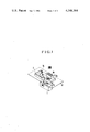
- FIG. 1 is a disassembled perspective view of a flash unit slide-type power switch embodying features of the present invention.
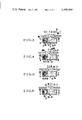
- FIG. 2 is a sectional view of the power switch of FIG. 1.
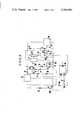
- FIG. 3 is an electrical circuit for the flash unit associated with the switch of FIG. 1.
- FIGS. 4 to 6 show the relationship between the elements of the power switch shown in FIG. 1 in each of its positions.
- a case 1 for the slide switch body forms a notch 2 which permits passage, with play, of a switch dial, knob or handle 3 movable between a first position (to be described) and a second position shown in FIG. 1.
- An operating lever 5 completely covers the handle 3 and carries a base plate 5a with legends "OFF” indicating that the power source switch SWM is in an OFF mode, "ON” indicating that the switch SWM is set in an ON mode, and "TIMER” indicating that the switch is set in a TIMER mode.
- the lower part of the base plate 5a carries a fixed guide (not shown in the drawing) to be inserted with play in the guide groove (not shown in the drawing) on the upper surface 1a of the case 1.
- the side surface of the base plate 5a is provided with a click groove 5b for engaging the bent part 7a of the spring 7 above.
- the above spring 7 in addition to the bent part 7a has a U-shaped part 7b, secured at a predetermined position on the case 1 by means not shown in the drawing.
- a light shading display plate 9 forms a display window 9a at the position opposite to the letters provided on the base plate 5a.
- a part of the display window 9a is 80 as removed so as to allow the free movement of the operating lever 5.
- FIG. 2 is a section showing the power source switch SWM in FIG. 1 mounted on the flash unit.
- a projection 5c of the operation lever 5 engages a notch 11a on the back cover 11 of the flash unit so that a part of projection 5c extends out of the surface of the back cover 11.
- the lower surface of the operation lever 5 forms a concavity 5d sufficient to allow the knob 3 to move from the first position in FIG. 4 into the second position in FIG. 2 when the operation lever 5 assumes the neutral position (the aforementioned "TIMER" position).
- the display plate 9 Inserted between the upper/surface of the lever 5 and the lower surface of the back cover 11 is the display plate 9 which is not shown in FIGS. 2 to 6.
- a release type electromagnet 13 and a spring 15 are provided in the case 1.
- the magnet includes a permanent magnet 13a secured on a part of the switch knob 3 and a coil 13c wound on a yoke 13b. Wires of the coil 13c pass through holes 1b and 1c provided on the side surface of the case 1.
- a contact member 17 secured on the lower part of the case possesses an extension 17a which projects into a concavity 3a of the handle 3.
- a movable contact member 19 secured on the concavity 3a of the handle 3 comes into contact with the stationary contact member 17 during translation of the handle 3 to the position shown in FIG. 4.
- FIG. 3 shows an electrical circuit diagram for the flash unit shown in FIGS. 1 and 2.
- FIG. 3 includes a power source battery 21, a DC--DC converter 23, a rectifying diode 25, a main capacitor 27 connected to the cathode of the above-mentioned diode 25 through a coil 29 so as to store the flash energy, and a noise killing diode 37 connected in parallel to the coil 29.
- a conventional discharge tube 3 and a thyristor 34 are connected in series with each other to form a series circuit which is connected in parallel to a series circuit composed of the main capacitor and the coil 29.
- the circuit further includes a conventional commutating capacitor 35, resistors 37 and 39 forming a charge circuit for the capacitor 35, a subsidary thyristor 41 connected between the capacitor 35 and the main thyristor 34, a capacitor 43 connected to the capacitor 35 through the resistor 45 to control the conductivity of the main thyristor 34, a resistor 47 connected between the gate and the cathode of the main thyristor 34, a conventional control circuit 49 for sensing the light reflected from the object so as to deliver the flash stop signal when the amount of the sensed light has reached a certain determined value, a resistor 51 connected to the output terminal of the control circuit and in parallel between the gate and the cathode of the subsidiary thyristor 41, a resistor 53 connected to the diode 25 through the resistor 37, a resistor 57 connected to the resistor 53 through the conventional neon tube 55, a capacitor 59 and a resistor 61 for forming a differentiating circuit, and a diode 63 connected
- the U-shaped part 7b of the spring 7 shown in FIG. 1 urges the base plate 5a of the operation lever 5 to the right so as to automatically move the base plate 5a to the right.
- the base plate 5a returns to the position at which the click groove 5b provided on the end surface of the base plate 5a opposes the bent part 7a of the spring 7, the bent part 7a enters the click groove 5b as is shown in FIG. 1.
- the slide motion of the base plate 5a and the operation lever 5 now stops. At this time the letters "TIMER" appears in the display window 9a so as to indicate that the TIMER mode has started. (The position at this time is shown in FIG. 5).
- the main capacitor 27 When the DC--DC converters starts oscillating, the main capacitor 27 is charged through the diode 25 and the coil 29 and the terminal voltage of the capacitor 27 goes up rapidly. When the terminal voltage reaches a predetermined value, the neon tube is lit. Current runs through the resistor 57 through the resistors 37 and 53, and the neon tube 55, in such a manner that a positive pulse appears at the output terminal of the differentiating circuit 59, 61 so as to reset the content of the counter 65. After the reset, when an oscillation pulse is delivered to the input terminal IN from the DC--DC converter 23 through the voltage dividing circuit composed of the resistors 81 and 83, the counter starts counting again and the timer mode is established again.
- a flash photography is taken.
- the discharge tube 33 emits a flash
- the control circuit 49 delivers a flash stop signal and the subsidary thyristor 41 assumes the conductive state.
- the charges in the capacitors 35 and 43 now discharged through the thyrister 41 so that the main thyristor 34 is reversed out of the conductive state into the non-conductive state.
- the discharge tube 33 now stops emitting light so as to terminate the flash photography.
- the neon tube 55 goes out to indicate that a flash photograph has properly been taken.
- the charge of the capacitors 35 and 43 is also completely discharged, so that also in this case the above-mentioned neon tube 55 is put out.
- the DC--DC converter 23 continues the oscillation because the power source switch SWM is in the TIMER mode as is shown in FIG. 5. Hence the counter continues to count the oscillation pulses. Although the counter 65 is reset when the neon tube 55 is lit, the counter 65 continues counting the oscillation pulse because the power source switch SWM remains in the TIMER mode after the neon tube 55 is lit.
- the freedom of the movement of the switch knob is guaranteed by virtue of the space in the concave part or recess of the operating levers at the neutral position. Hence, even if something lies on the operating lever or the operating lever is in contact with something such as the camera, the switch knob can be automatically moved without being influenced thereby. This is quite advantageous.
- the DC-DC converter as the oscillation source of the counter as is shown in FIG. 3, makes possible a flash unit of simple construction. Also, constructing the counter as is shown in FIG. 3, to be reset to a desired level when the main capacitor has been charged, causes the time formed with the counter to be unusually precise because the counter counts the oscillation pulses after the oscillation of the DC-DC counter is stabilized.
Landscapes
- Slide Switches (AREA)
Abstract
Disclosed is a slide switch in which a slide is slidable between a first position and a second position. A holding arrangement holds the slide in the second position when the slide has moved into the second position and permits the slide to return from the second position to the first position after a given lapse of time. A manually operable lever covering the slide serves to operate the slide. The lever is held at least at one position and forms a recess sufficiently large to enable the slide to return from the second position to the first position.
Description
1. Field of the Invention
This invention relates to a slide switch, particularly one whose switch handle automatically returns to a predetermined position.
2. Description of the Prior Art
Recently, proposals have been made for slide switches which automatically return the switch handle to an initial position, in which it opens a circuit after a predetermined time in response to an output signal.
Such a switch would be advantageous as the main switch of a camera flash unit, where a photographer may overlook de-energizing the unit after use. However, because the switch handle of the switch normally projects beyond the surface of the unit, other devices loaded in the case with the unit, such as the camera, or lenses, may hinder the return operation of the unit to its initial position.
An object of the invention is to improve slide switches.
Another object of the invention is to avoid the aforementioned shortcomings.
Still another object of the invention is to provide a manually operable slide switch in which the switch handle can return to an initial position despite contact of the switch with other devices.
Another object of the present invention is to provide a manually operable slide switch of the aforementioned type for an electronic flash unit.
The various features of novelty characterizing the invention are pointed out in the claims. Other objects and advantages of the invention will be evident from the following detailed description when read in light of the accompanying drawings.
FIG. 1 is a disassembled perspective view of a flash unit slide-type power switch embodying features of the present invention.
FIG. 2 is a sectional view of the power switch of FIG. 1.
FIG. 3 is an electrical circuit for the flash unit associated with the switch of FIG. 1.
FIGS. 4 to 6 show the relationship between the elements of the power switch shown in FIG. 1 in each of its positions.
In FIG. 1, a case 1 for the slide switch body forms a notch 2 which permits passage, with play, of a switch dial, knob or handle 3 movable between a first position (to be described) and a second position shown in FIG. 1. An operating lever 5 completely covers the handle 3 and carries a base plate 5a with legends "OFF" indicating that the power source switch SWM is in an OFF mode, "ON" indicating that the switch SWM is set in an ON mode, and "TIMER" indicating that the switch is set in a TIMER mode. The lower part of the base plate 5a carries a fixed guide (not shown in the drawing) to be inserted with play in the guide groove (not shown in the drawing) on the upper surface 1a of the case 1. The side surface of the base plate 5a is provided with a click groove 5b for engaging the bent part 7a of the spring 7 above. The above spring 7 in addition to the bent part 7a has a U-shaped part 7b, secured at a predetermined position on the case 1 by means not shown in the drawing. A light shading display plate 9 forms a display window 9a at the position opposite to the letters provided on the base plate 5a. A part of the display window 9a is 80 as removed so as to allow the free movement of the operating lever 5.
FIG. 2 is a section showing the power source switch SWM in FIG. 1 mounted on the flash unit. In FIG. 2, a projection 5c of the operation lever 5 engages a notch 11a on the back cover 11 of the flash unit so that a part of projection 5c extends out of the surface of the back cover 11. Further, the lower surface of the operation lever 5 forms a concavity 5d sufficient to allow the knob 3 to move from the first position in FIG. 4 into the second position in FIG. 2 when the operation lever 5 assumes the neutral position (the aforementioned "TIMER" position). Inserted between the upper/surface of the lever 5 and the lower surface of the back cover 11 is the display plate 9 which is not shown in FIGS. 2 to 6.
A release type electromagnet 13 and a spring 15 are provided in the case 1. The magnet includes a permanent magnet 13a secured on a part of the switch knob 3 and a coil 13c wound on a yoke 13b. Wires of the coil 13c pass through holes 1b and 1c provided on the side surface of the case 1. A spring 15 pressed against the side surface of the case and the end surface of the knob 3, as is shown in the drawing, normally urges the handle 3 to the right. A contact member 17 secured on the lower part of the case possesses an extension 17a which projects into a concavity 3a of the handle 3. A movable contact member 19 secured on the concavity 3a of the handle 3 comes into contact with the stationary contact member 17 during translation of the handle 3 to the position shown in FIG. 4.
FIG. 3 shows an electrical circuit diagram for the flash unit shown in FIGS. 1 and 2. FIG. 3 includes a power source battery 21, a DC--DC converter 23, a rectifying diode 25, a main capacitor 27 connected to the cathode of the above-mentioned diode 25 through a coil 29 so as to store the flash energy, and a noise killing diode 37 connected in parallel to the coil 29. A conventional discharge tube 3 and a thyristor 34 are connected in series with each other to form a series circuit which is connected in parallel to a series circuit composed of the main capacitor and the coil 29. The circuit further includes a conventional commutating capacitor 35, resistors 37 and 39 forming a charge circuit for the capacitor 35, a subsidary thyristor 41 connected between the capacitor 35 and the main thyristor 34, a capacitor 43 connected to the capacitor 35 through the resistor 45 to control the conductivity of the main thyristor 34, a resistor 47 connected between the gate and the cathode of the main thyristor 34, a conventional control circuit 49 for sensing the light reflected from the object so as to deliver the flash stop signal when the amount of the sensed light has reached a certain determined value, a resistor 51 connected to the output terminal of the control circuit and in parallel between the gate and the cathode of the subsidiary thyristor 41, a resistor 53 connected to the diode 25 through the resistor 37, a resistor 57 connected to the resistor 53 through the conventional neon tube 55, a capacitor 59 and a resistor 61 for forming a differentiating circuit, and a diode 63 connected to the output terminal of the differentiating circuit so as to cut negative pulses a presettable counter 65 includes a reset pulse input terminal R for receiving the positive pulse produced in the differentiating circuit 59, 61 and an input terminal IN for receiving the oscillation pulse produced in the DC--DC converter 23 the base of a npn transistor 64 is connected to the output terminal OUT of the counter 65 through the resistor 67. Member 13c is the exciting coil in FIG. 2, 17 is the fixed contact piece in FIG. 2, 19 is the movable contact piece in FIG. 2. A conventional trigger circuit 71 for triggering the discharge tube is actuated by a trigger switch 73.
In operation when the operating lever 5 of the power source switch SWM in the position shown in FIG. 2 is manually moved to the left, the end surface 5d is brought into contact with the end surface 3d of the knob 3. When the lever 5 is moved further to the left against the force of the spring 15 until the permanent magnet 13a forming the armature of the magnet attracts the end surface of the yoke 13b, the movable contact member 19 is brought into contact with the fixed contact piece 17 as is shown in FIG. 4. The DC--DC converter 23 shown in FIG. 3 is now connected to the power source 21 through the power source switch SWM so as to start oscillating.
When the operation lever 5 is now freed, the U-shaped part 7b of the spring 7 shown in FIG. 1 urges the base plate 5a of the operation lever 5 to the right so as to automatically move the base plate 5a to the right. When the base plate 5a returns to the position at which the click groove 5b provided on the end surface of the base plate 5a opposes the bent part 7a of the spring 7, the bent part 7a enters the click groove 5b as is shown in FIG. 1. The slide motion of the base plate 5a and the operation lever 5 now stops. At this time the letters "TIMER" appears in the display window 9a so as to indicate that the TIMER mode has started. (The position at this time is shown in FIG. 5). When the DC--DC converters starts oscillating, the main capacitor 27 is charged through the diode 25 and the coil 29 and the terminal voltage of the capacitor 27 goes up rapidly. When the terminal voltage reaches a predetermined value, the neon tube is lit. Current runs through the resistor 57 through the resistors 37 and 53, and the neon tube 55, in such a manner that a positive pulse appears at the output terminal of the differentiating circuit 59, 61 so as to reset the content of the counter 65. After the reset, when an oscillation pulse is delivered to the input terminal IN from the DC--DC converter 23 through the voltage dividing circuit composed of the resistors 81 and 83, the counter starts counting again and the timer mode is established again.
After a lapse of a predetermined time, a flash photography is taken. The discharge tube 33 emits a flash, the control circuit 49 delivers a flash stop signal and the subsidary thyristor 41 assumes the conductive state. The charges in the capacitors 35 and 43 now discharged through the thyrister 41 so that the main thyristor 34 is reversed out of the conductive state into the non-conductive state. The discharge tube 33 now stops emitting light so as to terminate the flash photography.
On the other hand, when the thyrister 41 becomes conductive as mentioned, the neon tube 55 goes out to indicate that a flash photograph has properly been taken. Hereby, in case of the flash light photography that the above-mentioned flash stop signal is not produced from the control circuit 49, for example, in case the object is too far or in case the manual flash mode is set, the charge of the capacitors 35 and 43 is also completely discharged, so that also in this case the above-mentioned neon tube 55 is put out.
When the flash unit is loaded and the power source switch SWM remains closed after termination of the flash light photography, the DC--DC converter 23 continues the oscillation because the power source switch SWM is in the TIMER mode as is shown in FIG. 5. Hence the counter continues to count the oscillation pulses. Although the counter 65 is reset when the neon tube 55 is lit, the counter 65 continues counting the oscillation pulse because the power source switch SWM remains in the TIMER mode after the neon tube 55 is lit.
When the level at the output terminal of the timer circuit turns high after the lapse of a time preset on the counter 65, the transistor 69 at the output terminal of the timer circuit becomes conductive and the exciting current runs through the coil 13c of the magnet 13. This releases the yoke 13b from the armature 13a shown in FIG. 2. Thus, the force of the spring 15 moves the switch knob 3 of the strength to the right within the case 1 until the end surface 3d contacts the end surface 5dd of the concave part 5d of the operation lever 5 as is shown in FIG. 6. The knob 3 then stops moving. When the switch knob 3 is moved into the position shown in FIG. 6, the contact of the movable contact member 19 with the fixed contact member 17 is discontinued, so that the current supply to the circuit of the flash unit and the driving circuit for the coil 13c is interrupted.
On the other hand, although the switch knob 3 is automatically moved toward the initial position in the concave part 5d of the operation lever 5 as explained, the word "TIMER" remains displayed in the display window shown in FIG. 1 because the operating lever 5 is kept at the position as shown in FIG. 1, the bent part 7a of the spring 7 being engaged in the click groove 5b.
When the operating lever 5 is forced out of the position shown in FIG. 5 to the position shown in FIG. 2 while the power switch SWM is in the TIMER mode, namely in the condition shown in FIG. 5, the movable contact member 9 is released from the fixed contact member 17. This occurs because the end surface 5ddA of the concave portion 5d of the operating lever 5 slides the switch handle 3 into the position shown in FIG. 2. This interrupts the current supply to the power source.
As explained, in accordance with the present invention, the freedom of the movement of the switch knob is guaranteed by virtue of the space in the concave part or recess of the operating levers at the neutral position. Hence, even if something lies on the operating lever or the operating lever is in contact with something such as the camera, the switch knob can be automatically moved without being influenced thereby. This is quite advantageous.
Using the DC-DC converter as the oscillation source of the counter as is shown in FIG. 3, makes possible a flash unit of simple construction. Also, constructing the counter as is shown in FIG. 3, to be reset to a desired level when the main capacitor has been charged, causes the time formed with the counter to be unusually precise because the counter counts the oscillation pulses after the oscillation of the DC-DC counter is stabilized.
Claims (11)
1. A slide switch comprising:
(a) sliding means slidable between a first position and a second position;
(b) holding means for releasably holding the sliding means in the second position when the sliding means assumes the second position and automatically enabling the sliding means to return from the second position to the first position after the lapse of a predetermined time; and
(c) a manually operable lever over the sliding means to cover the sliding means and coupled with the sliding means to operate the sliding means; said lever being held at least at one position and having a recess sufficient for enabling the sliding means to return from the second position to the first position when the sliding means has been held at the second position.
2. A slide switch according to claim 1, wherein the lever includes a wall at the recess and the sliding means includes a projection movable by the wall at the recess of the lever.
3. A slide switch according to claim 1, wherein the lever consists of hard material.
4. A slide switch according to claim 1, wherein the holding means includes a spring in contact with the sliding means in order to return the sliding means from the second position to the first position.
5. A slide switch according to claim 4, wherein the holding means includes a magnet for attracting the sliding means toward the second position against the force of the spring.
6. A slide switch for an electronic flash unit device, comprising:
(a) sliding means slidable between a first position and the second position;
(b) holding means for holding the sliding means in the second position when the sliding means has moved into the second position and enabling the sliding means to return from the second position to the first position after lapse of a predetermined time;
(c) a manually operable lever positioned over the sliding means to cover the sliding means and coupled with the sliding means to operate the sliding means, said lever being held at least at one position and having a recess sufficient for enabling the sliding means to return from the second position to the first position when the sliding means has been held at the one position; and
(d) a pair of contact members in the power line of the flash device, said members being located at positions at which they contact each other when the sliding means has been moved into the second position.
7. A slide switch according to claim 6, wherein at least one of the contact members is secured on a part of the sliding means.
8. A slide switch according to claim 7, wherein the lever includes a wall at the recess and the sliding means includes a projection movable by the wall at the recess of the lever.
9. A slide switch according to claim 7, wherein the lever consists of hard material.
10. A slide switch according to claim 7, wherein the holding means includes a spring in contact with the sliding means to return the sliding means from the second position to the first position.
11. A slide switch according to claim 7, wherein the holding means includes a magnet for attracting the sliding means toward the second position against the force of the spring.
Applications Claiming Priority (2)
| Application Number | Priority Date | Filing Date | Title |
|---|---|---|---|
| JP54-134460 | 1979-10-17 | ||
| JP13446079A JPS5657215A (en) | 1979-10-17 | 1979-10-17 | Slide switch |
Publications (1)
| Publication Number | Publication Date |
|---|---|
| US4348564A true US4348564A (en) | 1982-09-07 |
Family
ID=15128843
Family Applications (1)
| Application Number | Title | Priority Date | Filing Date |
|---|---|---|---|
| US06/196,438 Expired - Lifetime US4348564A (en) | 1979-10-17 | 1980-10-14 | Slide switch |
Country Status (2)
| Country | Link |
|---|---|
| US (1) | US4348564A (en) |
| JP (1) | JPS5657215A (en) |
Cited By (4)
| Publication number | Priority date | Publication date | Assignee | Title |
|---|---|---|---|---|
| US4672229A (en) * | 1985-12-12 | 1987-06-09 | Southwest Laboratories, Inc. | Wall-mounted touch control switch |
| US5806665A (en) * | 1997-08-06 | 1998-09-15 | American Tack & Hardware Co., Inc. | Arcuate switch actuator |
| US20040083571A1 (en) * | 2002-11-01 | 2004-05-06 | Lg Electronics Inc. | Upright vacuum cleaner |
| US20100264003A1 (en) * | 2009-04-20 | 2010-10-21 | Heien Troy A | Mechanical delay timer |
Citations (5)
| Publication number | Priority date | Publication date | Assignee | Title |
|---|---|---|---|---|
| US3209097A (en) * | 1963-08-20 | 1965-09-28 | Jr Bernard Edward Shlesinger | Magnetic snap action switch |
| US3833784A (en) * | 1972-12-29 | 1974-09-03 | Skil Corp | Safety slide switch |
| US3857000A (en) * | 1973-07-05 | 1974-12-24 | Texas Instruments Inc | Multi-position slide switch assembly with housing means holding common conductive rail in fixed abutting relationship with end terminals of fixed contact array |
| US4058693A (en) * | 1974-09-26 | 1977-11-15 | K. A. Schmersal & Co. Schaltgeratefabrik | Electric snap-action switch |
| US4164635A (en) * | 1978-03-22 | 1979-08-14 | Time Systems, Inc. | Wall switch timer |
Family Cites Families (1)
| Publication number | Priority date | Publication date | Assignee | Title |
|---|---|---|---|---|
| JPS59957B2 (en) * | 1976-11-09 | 1984-01-09 | 株式会社セコ−技研 | electronic light emitter |
-
1979
- 1979-10-17 JP JP13446079A patent/JPS5657215A/en active Pending
-
1980
- 1980-10-14 US US06/196,438 patent/US4348564A/en not_active Expired - Lifetime
Patent Citations (5)
| Publication number | Priority date | Publication date | Assignee | Title |
|---|---|---|---|---|
| US3209097A (en) * | 1963-08-20 | 1965-09-28 | Jr Bernard Edward Shlesinger | Magnetic snap action switch |
| US3833784A (en) * | 1972-12-29 | 1974-09-03 | Skil Corp | Safety slide switch |
| US3857000A (en) * | 1973-07-05 | 1974-12-24 | Texas Instruments Inc | Multi-position slide switch assembly with housing means holding common conductive rail in fixed abutting relationship with end terminals of fixed contact array |
| US4058693A (en) * | 1974-09-26 | 1977-11-15 | K. A. Schmersal & Co. Schaltgeratefabrik | Electric snap-action switch |
| US4164635A (en) * | 1978-03-22 | 1979-08-14 | Time Systems, Inc. | Wall switch timer |
Cited By (6)
| Publication number | Priority date | Publication date | Assignee | Title |
|---|---|---|---|---|
| US4672229A (en) * | 1985-12-12 | 1987-06-09 | Southwest Laboratories, Inc. | Wall-mounted touch control switch |
| US5806665A (en) * | 1997-08-06 | 1998-09-15 | American Tack & Hardware Co., Inc. | Arcuate switch actuator |
| US20040083571A1 (en) * | 2002-11-01 | 2004-05-06 | Lg Electronics Inc. | Upright vacuum cleaner |
| US7174604B2 (en) * | 2002-11-01 | 2007-02-13 | Lg Electronics Inc. | Upright vacuum cleaner with sliding power indicator switch |
| US20100264003A1 (en) * | 2009-04-20 | 2010-10-21 | Heien Troy A | Mechanical delay timer |
| US8263883B2 (en) * | 2009-04-20 | 2012-09-11 | Heien Troy A | Mechanical delay timer |
Also Published As
| Publication number | Publication date |
|---|---|
| JPS5657215A (en) | 1981-05-19 |
Similar Documents
| Publication | Publication Date | Title |
|---|---|---|
| US4007469A (en) | Photographic apparatus with plurality of selectively determinable operational modes | |
| US4084167A (en) | Flash and camera device | |
| US4231645A (en) | Camera with telescoping dual actuators | |
| US4130780A (en) | Electronic photoflash | |
| US4021824A (en) | Flash light photographic system for camera | |
| US4348564A (en) | Slide switch | |
| US4096492A (en) | Camera with detachable electronic flash unit and exposure control system therefor | |
| KR100568582B1 (en) | Flash device | |
| JPS587620A (en) | Camera power supply holding device | |
| US4163178A (en) | Flash light discharge device | |
| US4025817A (en) | Trigger device for an electronic flash unit | |
| GB1565601A (en) | Photographic flash apparatus | |
| US4306799A (en) | Dual actuator switches for flash and exposure modes | |
| US4140382A (en) | Drive control circuit of motor drive unit | |
| CA1047818A (en) | Flash camera with combined mode and aperture switch | |
| US4101792A (en) | Mechanically-powered electric generator for instant-photographic camera and other apparatus | |
| US4068243A (en) | Photographic camera with an extrinsic coordinating system | |
| US4220407A (en) | Camera with film transport motor powered by battery which also charges a flash unit during intervals of transport motor inoperativeness | |
| US4545666A (en) | Light emission blocking device of a camera capable of effecting flashlight photography | |
| US3904844A (en) | Trigger switch with lost motion connection | |
| US4203662A (en) | Trigger mechanism for photographic camera provided with motor-driven film-transport mechanism | |
| US4141637A (en) | Electrically controlled self-timer devices for single lens reflex cameras | |
| US6434338B1 (en) | Camera with dual-function battery/manual operating button unit | |
| US3724344A (en) | Camera flashgun shoe | |
| US3964080A (en) | Electromagnetic trigger device in a camera capable of effecting time photography |
Legal Events
| Date | Code | Title | Description |
|---|---|---|---|
| STCF | Information on status: patent grant |
Free format text: PATENTED CASE |