US4348548A - Insulator for covering electrical cables - Google Patents
Insulator for covering electrical cables Download PDFInfo
- Publication number
- US4348548A US4348548A US06/074,428 US7442879A US4348548A US 4348548 A US4348548 A US 4348548A US 7442879 A US7442879 A US 7442879A US 4348548 A US4348548 A US 4348548A
- Authority
- US
- United States
- Prior art keywords
- insulator
- cables
- connector
- openings
- spacer
- Prior art date
- Legal status (The legal status is an assumption and is not a legal conclusion. Google has not performed a legal analysis and makes no representation as to the accuracy of the status listed.)
- Expired - Lifetime
Links
Images


Classifications
-
- H—ELECTRICITY
- H01—ELECTRIC ELEMENTS
- H01R—ELECTRICALLY-CONDUCTIVE CONNECTIONS; STRUCTURAL ASSOCIATIONS OF A PLURALITY OF MUTUALLY-INSULATED ELECTRICAL CONNECTING ELEMENTS; COUPLING DEVICES; CURRENT COLLECTORS
- H01R12/00—Structural associations of a plurality of mutually-insulated electrical connecting elements, specially adapted for printed circuits, e.g. printed circuit boards [PCB], flat or ribbon cables, or like generally planar structures, e.g. terminal strips, terminal blocks; Coupling devices specially adapted for printed circuits, flat or ribbon cables, or like generally planar structures; Terminals specially adapted for contact with, or insertion into, printed circuits, flat or ribbon cables, or like generally planar structures
- H01R12/50—Fixed connections
- H01R12/59—Fixed connections for flexible printed circuits, flat or ribbon cables or like structures
-
- Y—GENERAL TAGGING OF NEW TECHNOLOGICAL DEVELOPMENTS; GENERAL TAGGING OF CROSS-SECTIONAL TECHNOLOGIES SPANNING OVER SEVERAL SECTIONS OF THE IPC; TECHNICAL SUBJECTS COVERED BY FORMER USPC CROSS-REFERENCE ART COLLECTIONS [XRACs] AND DIGESTS
- Y10—TECHNICAL SUBJECTS COVERED BY FORMER USPC
- Y10T—TECHNICAL SUBJECTS COVERED BY FORMER US CLASSIFICATION
- Y10T428/00—Stock material or miscellaneous articles
- Y10T428/24—Structurally defined web or sheet [e.g., overall dimension, etc.]
- Y10T428/24273—Structurally defined web or sheet [e.g., overall dimension, etc.] including aperture
- Y10T428/24322—Composite web or sheet
- Y10T428/24331—Composite web or sheet including nonapertured component
Definitions
- the present invention relates to insulators for covering electric cables and, more particularly, to such insulators which are especially adapted for use in connection with flat multiconductor cables.
- a series of joints between selected conductors of two overlapping flat multiconductor cables are formed using metallic connectors which extend beyond the surface of at least one of the cables.
- the bare metallic connectors in contact with energized electrical conductors themselves become electrically "hot” and can cause anyone who, directly or indirectly, contacts such connectors to receive a severe electrical shock.
- the flat multiconductor cable constructed in accordance with the teaching in U.S. Pat. No. 4,219,928 issued to Kuo on Sept. 2, 1980 and owned by the assignee of the instant invention, and by this reference made a part hereof, have a series of parallel flat, insulated conductors separated from adjacent conductors by flattened depressed regions of insulation only which, due to the presence of a score line, lend themselves to tearing should it be desired to separate the conductors from one another. These flattened, depressed regions are significantly thinner than the adjacent conductor insulation portions of the cable.
- the relatively thick insulating spacers placed on the conductor insulation fail to conform to the depressed regions leaving pathways between the cable surface and the insulating spacers where moisture, dirt or other contaminants can enter. Due to the size of the holes in the insulating spacers, they often overlap the depressed regions permitting the connectors to be subjected to any moisture, dirt or contaminants contained therein, leading to a shorting of or other injury to the joints and cables.
- the present invention overcomes many of the disadvantages and shortcomings of the device discussed above by providing an insulator with a spacer having round apertures or holes therein which closely conform to the maximum profile of the metallic connector oriented only in a selected direction and so positioned in the cable as to permit a significant insulation barrier about the connector to be created without extending into the depressed regions to either side of the conductor. With such an arrangement, any moisture, dirt or other contaminants will not be permitted to leave the depressed region and enter into the aperture in which a connector is placed.
- the inclusion of positioning apertures and slots in the insulators permit them to be properly placed above and below the joints employing a tool of the type described and claimed in U.S. Pat. No. 4,280,279, issued on July 28, 1981, entitled "Alignment Tool" and owned by the assignee of the instant invention. It is an object of this invention to provide an improved insulator for flat multiconductor cables.
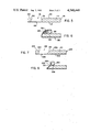
- FIG. 1 is a top plan view of an insulator for covering electric cables constructed in accordance with the concepts of the invention.
- FIG. 2 is a side elevational view, in section, of the insulator of FIG. 1 taken along the lines of 2--2 in FIG. 1.
- FIG. 3 is a top plan view of two overlapping flat multiconductor cables coupled to one another by a series of connectors.
- FIG. 4 is a side elevation, in section, of one of the flat multiconductor cables of FIG. 3 taken along the lines 4--4.
- FIG. 5 is a side elevation, in section, of a flat multiconductor cable with an insulator constructed in accordance with the prior art adhered thereto.
- FIG. 6 is a side elevation, in section, of a flat multiconductor cable with an insulator constructed in accordance with the invention adhered thereto.
- FIG. 7 is a side elevation, in section, of a joint between two flat multiconductor cables insulated with insulators constructed in accordance with the invention adhered thereto.
- a first flat multiconductor cable 110 has its individual conductors 112, 114, 116 and 118 joined to like individual conductors 122, 124, 126 and 128, respectively, of a second flat multiconductor cable 120 by the connectors 132, 134, 136 and 138, respectively.
- the conductors are generally rectangular and are covered on both long sides by layers of insulation 130 and 140.
- the layers of insulation 130 and 140 may be adhered to themselves in the interstices between adjacent conductors as at 142, 144, 146 and at the cables ends as at 148 and 150, only ends 148 and 150 being shown in the drawing as adhered.
- a flattened, depressed region having a width significantly less than the adjacent areas where a conductor is located resulting in a natural trough or passage along the longitudinal axis of the cable 110.
- Similar depressed regions are found in cable 120 as at 152, 154 and 156 and at the cable ends 158 and 160.
- a score line, such as 162 in depressed region 142 extends down the center of each of the depressed regions to permit the individual conductors to be separated from the full cable.
- conductor 112 can be removed from cable 110 by tearing along score line 162 in the depressed region 142.
- Insulator 10 includes a spacer 12 of insulating material covered on one surface by a thin clear film of electric insulation 14 and on the other by a layer of pressure-sensitive adhesive 18. At selected locations, holes 32 extend through spacer 12 to accommodate the connectors which protrude beyond the cables which the connectors join.
- the holes 32 are large enough to accept the connector in either of its two possible mirror positions. As can be clearly seen in FIG. 5, when an insulator 10 according to the above application, is placed over a flat multiconductor cable 110 some of the holes 32 extend beyond their associated conductors and over the depressed regions. Thus, hole 32c extends over depressed region 142, while hole 32d overlies a portion of depressed region 144 and hole 32e extends over a portion of depressed region 146. Any moisture, dirt or other contaminants which are deposited upon the surface of the cable 110 are able to travel down one of the depressed regions 142, 144 or 146 and thus contact exposed connectors (not shown) in the holes 32b, 32c or 32d respectively. Such moisture, dirt or other contaminants could short out the connection or lead to the deterioration of the connector or joint.
- Insulator 164 constructed in accordance with the concepts of the invention is shown.
- Insulator 164 consists of a spacer layer 166 having a thickness equal to the projection of a connector extending above the surface of the cable to be insulated.
- spacer 166 Within spacer 166 are a series of round holes 168 positioned at all of the necessary interconnect positions for joining two flat multiconductor cables.
- the holes 168 are significantly smaller than the holes 32 of my copending application due to the fixing of the positions of the connectors to the single orientation shown in FIG. 3. It should be understood that the holes 168 could take on any other desirable shape such as that of the connector itself, etc. Round holes were chosen because of manufacturing simplicity.
- spacer 166 Over the top of a portion of spacer 166 is placed a thin, clear insulating layer 170 laminated thereto while a layer of pressure-sensitive adhesive 172 is placed on the bottom of spacer 166 and protected until use by a release layer 174.
- a circular aperture 176 and an elongated slot 178 are placed in spacer 166 to enable it to be positioned upon the tool which is the subject of my patent, U.S. Pat. No. 4,280,279, issued on July 28, 1981 and entitled "Alignment Tool.” This tool aligns the insulator 164 with the flat multiconductor cables it is to insulate.
- FIG. 6 the installation of insulator 164 to flat multiconductor cable 110 is shown. If can be appreciated that each of the holes 168a, 168b, 168c and 168d are now centered over its respective conductor 112, 114, 116 and 118. The holes are not permitted to extend over any of the depressed regions 142, 144 and 146 thus sealing the connectors in the holes 168a, 168b, 168c and 168d from any moisture, dirt or other contaminants which might be present in the depressed regions 142, 144 or 146.
- a substantial portion of the insulation between the holes 168 extends between the holes and the edges of the depressed region insuring a seal to prevent the entry of any moisture, dirt or other contaminants into the holes 168.
- the connectors 132, 134, 136 and 138 will be set centrally into the overlapped conductors so that approximately equal insulative barriers extend to either side of the holes 168 to the adjacent depressed regions.
- FIG. 7 shows a completed splice of flat multiconductor cables 110 and 120 with insulators 166 placed below and atop the joint formed by connector 132.
Landscapes
- Insulated Conductors (AREA)
Abstract
An insulator for covering an electric cable has circular recesses for receiving any portions of a connector which extend beyond a surface of the cable covered by the insulator. If the connector extends between overlapping portions of a pair of cables, the connector and the overlapping portions of the cables can be completely enveloped by sandwiching them between a pair of insulators. The diameter of each recess is chosen so as to closely accommodate the extending portions of its associated connector and to provide a substantial barrier of insulation about the connector out to the edges of the cables being joined to prevent moisture, dirt and other contaminents from reaching the connector and causing its degradation or shorting.
Description
The present invention relates to insulators for covering electric cables and, more particularly, to such insulators which are especially adapted for use in connection with flat multiconductor cables.
In my U.S. Pat. No. 4,255,612, issued on Mar. 10, 1981, entitled "Insulator for Covering Electric Cables," which is owned by the assignee of the present invention, there is disclosed a technique for insulating the joints between the conductors of two flat multiconductor cables. The specification of that copending application is incorporated into this specification by reference thereto herein.
Briefly, a series of joints between selected conductors of two overlapping flat multiconductor cables are formed using metallic connectors which extend beyond the surface of at least one of the cables. The bare metallic connectors in contact with energized electrical conductors themselves become electrically "hot" and can cause anyone who, directly or indirectly, contacts such connectors to receive a severe electrical shock.
In my earlier application, it was proposed to electrically insulate the connectors by covering them with a flat sheet of relatively flexible electrical insulation supported by an insulating spacer of a thickness sufficient to accommodate the protruding portions of the metallic connectors. The spacers, caused to adhere to the surface of the cables themselves, served to provide a sufficient insulation barrier to prevent tracking across the cable surfaces from connector to connector. This was true despite the large size of the holes in the insulator to accommodate the connectors regardless of their orientation.
The flat multiconductor cable constructed in accordance with the teaching in U.S. Pat. No. 4,219,928 issued to Kuo on Sept. 2, 1980 and owned by the assignee of the instant invention, and by this reference made a part hereof, have a series of parallel flat, insulated conductors separated from adjacent conductors by flattened depressed regions of insulation only which, due to the presence of a score line, lend themselves to tearing should it be desired to separate the conductors from one another. These flattened, depressed regions are significantly thinner than the adjacent conductor insulation portions of the cable. As a result, the relatively thick insulating spacers placed on the conductor insulation fail to conform to the depressed regions leaving pathways between the cable surface and the insulating spacers where moisture, dirt or other contaminants can enter. Due to the size of the holes in the insulating spacers, they often overlap the depressed regions permitting the connectors to be subjected to any moisture, dirt or contaminants contained therein, leading to a shorting of or other injury to the joints and cables.
The present invention overcomes many of the disadvantages and shortcomings of the device discussed above by providing an insulator with a spacer having round apertures or holes therein which closely conform to the maximum profile of the metallic connector oriented only in a selected direction and so positioned in the cable as to permit a significant insulation barrier about the connector to be created without extending into the depressed regions to either side of the conductor. With such an arrangement, any moisture, dirt or other contaminants will not be permitted to leave the depressed region and enter into the aperture in which a connector is placed. The inclusion of positioning apertures and slots in the insulators permit them to be properly placed above and below the joints employing a tool of the type described and claimed in U.S. Pat. No. 4,280,279, issued on July 28, 1981, entitled "Alignment Tool" and owned by the assignee of the instant invention. It is an object of this invention to provide an improved insulator for flat multiconductor cables.
It is another object of this invention to provide an improved insulator that also seals the connectors of two flat multiconductor cables from the surrounding environment.
It is still another object of this invention to provide insulators which can be simply placed upon a flat multiconductor cable using a simple alignment tool.
It is still another object of this invention to provide an insulator with connector receiving apertures which closely conform to the profile of the connector and permit a seal to be created wholly on the surface of the joined conductors.
Other objects and features of the invention will be pointed out in the following description and claims and illustrated in the accompanying drawings, which disclose, by way of example, the principle of the invention, and the best mode which has been contemplated for carrying it out.
In the drawings in which similar elements are given similar reference characters.
FIG. 1 is a top plan view of an insulator for covering electric cables constructed in accordance with the concepts of the invention.
FIG. 2 is a side elevational view, in section, of the insulator of FIG. 1 taken along the lines of 2--2 in FIG. 1.
FIG. 3 is a top plan view of two overlapping flat multiconductor cables coupled to one another by a series of connectors.
FIG. 4 is a side elevation, in section, of one of the flat multiconductor cables of FIG. 3 taken along the lines 4--4.
FIG. 5 is a side elevation, in section, of a flat multiconductor cable with an insulator constructed in accordance with the prior art adhered thereto.
FIG. 6 is a side elevation, in section, of a flat multiconductor cable with an insulator constructed in accordance with the invention adhered thereto.
FIG. 7 is a side elevation, in section, of a joint between two flat multiconductor cables insulated with insulators constructed in accordance with the invention adhered thereto.
Turning now to FIGS. 3 and 4, a first flat multiconductor cable 110 has its individual conductors 112, 114, 116 and 118 joined to like individual conductors 122, 124, 126 and 128, respectively, of a second flat multiconductor cable 120 by the connectors 132, 134, 136 and 138, respectively. As is best seen in FIG. 4, the conductors are generally rectangular and are covered on both long sides by layers of insulation 130 and 140. The layers of insulation 130 and 140 may be adhered to themselves in the interstices between adjacent conductors as at 142, 144, 146 and at the cables ends as at 148 and 150, only ends 148 and 150 being shown in the drawing as adhered. In that there is no conductor at such locations, a flattened, depressed region is created having a width significantly less than the adjacent areas where a conductor is located resulting in a natural trough or passage along the longitudinal axis of the cable 110. Similar depressed regions are found in cable 120 as at 152, 154 and 156 and at the cable ends 158 and 160. A score line, such as 162 in depressed region 142, extends down the center of each of the depressed regions to permit the individual conductors to be separated from the full cable. Thus, conductor 112 can be removed from cable 110 by tearing along score line 162 in the depressed region 142.
As stated above, the presence of a bare metallic connector such as 132, 134, 136 or 138 engaging an energized conductor such as 112, 114, 116, 118, 122, 124, 126 or 128 itself becomes electrically "hot" so that one contacting such a connector could receive a severe electrical shock. To prevent this from happening, an insulator of the type set out in my U.S. Pat. No. 4,255,612 and shown in FIG. 5, can be employed. Insulator 10 includes a spacer 12 of insulating material covered on one surface by a thin clear film of electric insulation 14 and on the other by a layer of pressure-sensitive adhesive 18. At selected locations, holes 32 extend through spacer 12 to accommodate the connectors which protrude beyond the cables which the connectors join. The holes 32 are large enough to accept the connector in either of its two possible mirror positions. As can be clearly seen in FIG. 5, when an insulator 10 according to the above application, is placed over a flat multiconductor cable 110 some of the holes 32 extend beyond their associated conductors and over the depressed regions. Thus, hole 32c extends over depressed region 142, while hole 32d overlies a portion of depressed region 144 and hole 32e extends over a portion of depressed region 146. Any moisture, dirt or other contaminants which are deposited upon the surface of the cable 110 are able to travel down one of the depressed regions 142, 144 or 146 and thus contact exposed connectors (not shown) in the holes 32b, 32c or 32d respectively. Such moisture, dirt or other contaminants could short out the connection or lead to the deterioration of the connector or joint.
Referring now to FIGS. 1 and 2, an insulator 164 constructed in accordance with the concepts of the invention is shown. Insulator 164 consists of a spacer layer 166 having a thickness equal to the projection of a connector extending above the surface of the cable to be insulated. Within spacer 166 are a series of round holes 168 positioned at all of the necessary interconnect positions for joining two flat multiconductor cables. The holes 168 are significantly smaller than the holes 32 of my copending application due to the fixing of the positions of the connectors to the single orientation shown in FIG. 3. It should be understood that the holes 168 could take on any other desirable shape such as that of the connector itself, etc. Round holes were chosen because of manufacturing simplicity. Over the top of a portion of spacer 166 is placed a thin, clear insulating layer 170 laminated thereto while a layer of pressure-sensitive adhesive 172 is placed on the bottom of spacer 166 and protected until use by a release layer 174. A circular aperture 176 and an elongated slot 178 are placed in spacer 166 to enable it to be positioned upon the tool which is the subject of my patent, U.S. Pat. No. 4,280,279, issued on July 28, 1981 and entitled "Alignment Tool." This tool aligns the insulator 164 with the flat multiconductor cables it is to insulate.
Turning to FIG. 6, the installation of insulator 164 to flat multiconductor cable 110 is shown. If can be appreciated that each of the holes 168a, 168b, 168c and 168d are now centered over its respective conductor 112, 114, 116 and 118. The holes are not permitted to extend over any of the depressed regions 142, 144 and 146 thus sealing the connectors in the holes 168a, 168b, 168c and 168d from any moisture, dirt or other contaminants which might be present in the depressed regions 142, 144 or 146. In each instance, a substantial portion of the insulation between the holes 168 extends between the holes and the edges of the depressed region insuring a seal to prevent the entry of any moisture, dirt or other contaminants into the holes 168. The connectors 132, 134, 136 and 138 will be set centrally into the overlapped conductors so that approximately equal insulative barriers extend to either side of the holes 168 to the adjacent depressed regions.
FIG. 7 shows a completed splice of flat multiconductor cables 110 and 120 with insulators 166 placed below and atop the joint formed by connector 132.
While there have been shown and described and pointed out the fundamental novel features of the invention as applied to the preferred embodiments, it will be understood that various omissions and substitutions and changes of the form and details of the device illustrated and in its operation may be made by those skilled in the art, without departing from the spirit of the invention.
Claims (17)
1. In combination, a first multiconductor cable and a second multiconductor cable, said first and second cables each having conductor portions of a first predetermined thickness each conductor portion being separated from adjacent conductor portions by a flat depressed region of a second predetermined thickness less than said first predetermined thickness, said first and second cables having common overlapping portions and with specific conductors of said first multiconductor cable joined to specific conductors of said second multiconductor cables by means of electrical connectors which extend above the surfaces of the conductors portions a third predetermined height, and a pair of insulators positioned so as to sandwich said overlapping portions of said first and second multiconductor cables therebetween, said insulator including means forming an insulating barrier between said flat depressed regions and said connectors.
2. A combination according to claim 1, wherein each of said insulators defines at least one aperture for receiving a portion of said at least one connector which extends above a conductor portion of said overlapping portions of said cables.
3. A combination according to claim 1 wherein said insulator includes spacer means surrounding each connector and defining said barrier means, said spacer means being located on said conductor portions.
4. A combination according to claim 3 further including an insulating member on said spacer means and supported over said connectors.
5. A combination according to claim 3 wherein said surrounding spacer means defines an opening in registry with each of said conductor portions, the size of each such opening being less than the distance between said depressed regions along the lateral direction of said cables.
6. A combination according to claim 5 wherein said openings are substantially circular.
7. A combination according to claim 1 further including adhesive means joining said insulators and said cables.
8. An insulator for insulating the junctures between connected conductors of two or more substantially flat multiconductor cables comprising a spacer member having first and second opposed surfaces, said spacer member having a plurality of openings extending in an ordered pattern through said first and second surfaces and at least two spaced alignment apertures in configuration different from one another, an insulating member on said first surface of expanse sufficient to cover said openings and adhesive means on said second surface.
9. An insulator according to claim 8 further comprising liner means removably attached to said adhesive means.
10. An insulator according to claim 8 wherein said spacer member is substantially planar.
11. An insulator according to claim 10 wherein said spacer member defines a predetermined geometric area and wherein said insulating member lies within the perimetric boundaries of said geometric area excluding said alignment apertures whereby said alignment apertures are exposed.
12. An insulator according to claim 8 wherein said openings are substantially circular.
13. An insulator according to claim 8 wherein said alignment apertures comprise a round aperture and an elongated slot spaced therefrom, said round aperture and said slot extending through said first and second surfaces of said spacer member.
14. An insulator according to claim 8 wherein a first plurality of openings lie along a substantially straight line.
15. An insulator according to claim 14 wherein at least one further opening lies offset from said line.
16. An insulator according to claim 14 wherein a second plurality of openings, including one of said first plurality of openings lies in a second substantially straight line intersecting said first-mentioned straight line.
17. An insulator according to claim 8 wherein said insulating member comprises a substantially transparent layer.
Priority Applications (11)
| Application Number | Priority Date | Filing Date | Title |
|---|---|---|---|
| US06/074,428 US4348548A (en) | 1979-09-11 | 1979-09-11 | Insulator for covering electrical cables |
| SE8003813A SE427786B (en) | 1979-05-25 | 1980-05-21 | ELECTRICAL CABLE ISOLATOR |
| CA352,579A CA1130882A (en) | 1979-05-25 | 1980-05-23 | Insulator for covering electrical cables |
| GB8017088A GB2052182B (en) | 1979-05-25 | 1980-05-23 | Insulator for flat cable installation |
| MX182472A MX149277A (en) | 1979-05-25 | 1980-05-23 | IMPROVEMENTS IN INSULATED JUNCTION FOR ELECTRICAL CONNECTIONS OF FLAT CABLES |
| FR8011612A FR2457549A1 (en) | 1979-05-25 | 1980-05-23 | INSULATOR FOR COVERING ELECTRICAL CABLES |
| ES1980257683U ES257683Y (en) | 1979-05-25 | 1980-05-23 | INSULATOR TO ISOLATE THE JUNCTION BETWEEN TWO OR MORE ELECTRICAL CABLES |
| IT48769/80A IT1127851B (en) | 1979-05-25 | 1980-05-23 | INSULATOR TO COVER ELECTRIC CABLES |
| DE19803020039 DE3020039A1 (en) | 1979-05-25 | 1980-05-24 | INSULATION TO COVER ELECTRICAL CABLES |
| DE8014160U DE8014160U1 (en) | 1979-05-25 | 1980-05-24 | Device for encapsulating superposed and electrically and mechanically interconnected multi-conductor flat cables |
| HK636/85A HK63685A (en) | 1979-05-25 | 1985-08-22 | Insulator for covering electrical cables |
Applications Claiming Priority (1)
| Application Number | Priority Date | Filing Date | Title |
|---|---|---|---|
| US06/074,428 US4348548A (en) | 1979-09-11 | 1979-09-11 | Insulator for covering electrical cables |
Publications (1)
| Publication Number | Publication Date |
|---|---|
| US4348548A true US4348548A (en) | 1982-09-07 |
Family
ID=22119516
Family Applications (1)
| Application Number | Title | Priority Date | Filing Date |
|---|---|---|---|
| US06/074,428 Expired - Lifetime US4348548A (en) | 1979-05-25 | 1979-09-11 | Insulator for covering electrical cables |
Country Status (1)
| Country | Link |
|---|---|
| US (1) | US4348548A (en) |
Cited By (8)
| Publication number | Priority date | Publication date | Assignee | Title |
|---|---|---|---|---|
| US4551579A (en) * | 1982-10-08 | 1985-11-05 | Matsushita Electric Works, Ltd. | Construction of a connection for flat cables |
| US4630362A (en) * | 1981-10-26 | 1986-12-23 | Burndy Corporation | Apparatus for installing electrical on flat conductor cable |
| US4636017A (en) * | 1984-06-01 | 1987-01-13 | Harvey Hubbell Incorporated | Flat conductor cable |
| US4821409A (en) * | 1981-10-26 | 1989-04-18 | Burndy Corporation | Electrical connection apparatus for flat conductor cables and similar articles |
| US5262226A (en) * | 1990-03-16 | 1993-11-16 | Ricoh Company, Ltd. | Anisotropic conductive film |
| US6274814B1 (en) | 1999-11-08 | 2001-08-14 | Steven Iavarone | Decorative conduit raceway covering |
| EP1221575B2 (en) † | 2001-01-05 | 2010-09-15 | Koppens B.V. | Oven with fluid jet device |
| US20190279787A1 (en) * | 2016-09-26 | 2019-09-12 | Autonetworks Technologies, Ltd. | Flat wire, flat wire multilayer body, and fixing structure for flat wire |
Citations (5)
| Publication number | Priority date | Publication date | Assignee | Title |
|---|---|---|---|---|
| US3551270A (en) * | 1967-01-30 | 1970-12-29 | Melvin Sharkey | Bonding air-impervious flexible sheets using an adhesive,perforated,inner sheet and article produced thereby |
| US3989338A (en) * | 1974-11-08 | 1976-11-02 | Gosser Robert B | Push-pin assembly method and construction |
| US4143931A (en) * | 1977-01-28 | 1979-03-13 | Cir-Kit Concepts, Inc. | Flexible conductor strips for miniaturized electrical systems |
| US4219928A (en) * | 1979-05-25 | 1980-09-02 | Thomas & Betts Corporation | Flat cable and installing method |
| US4258974A (en) * | 1979-05-25 | 1981-03-31 | Thomas & Betts Corporation | Installation kit for undercarpet wiring system |
-
1979
- 1979-09-11 US US06/074,428 patent/US4348548A/en not_active Expired - Lifetime
Patent Citations (5)
| Publication number | Priority date | Publication date | Assignee | Title |
|---|---|---|---|---|
| US3551270A (en) * | 1967-01-30 | 1970-12-29 | Melvin Sharkey | Bonding air-impervious flexible sheets using an adhesive,perforated,inner sheet and article produced thereby |
| US3989338A (en) * | 1974-11-08 | 1976-11-02 | Gosser Robert B | Push-pin assembly method and construction |
| US4143931A (en) * | 1977-01-28 | 1979-03-13 | Cir-Kit Concepts, Inc. | Flexible conductor strips for miniaturized electrical systems |
| US4219928A (en) * | 1979-05-25 | 1980-09-02 | Thomas & Betts Corporation | Flat cable and installing method |
| US4258974A (en) * | 1979-05-25 | 1981-03-31 | Thomas & Betts Corporation | Installation kit for undercarpet wiring system |
Cited By (8)
| Publication number | Priority date | Publication date | Assignee | Title |
|---|---|---|---|---|
| US4630362A (en) * | 1981-10-26 | 1986-12-23 | Burndy Corporation | Apparatus for installing electrical on flat conductor cable |
| US4821409A (en) * | 1981-10-26 | 1989-04-18 | Burndy Corporation | Electrical connection apparatus for flat conductor cables and similar articles |
| US4551579A (en) * | 1982-10-08 | 1985-11-05 | Matsushita Electric Works, Ltd. | Construction of a connection for flat cables |
| US4636017A (en) * | 1984-06-01 | 1987-01-13 | Harvey Hubbell Incorporated | Flat conductor cable |
| US5262226A (en) * | 1990-03-16 | 1993-11-16 | Ricoh Company, Ltd. | Anisotropic conductive film |
| US6274814B1 (en) | 1999-11-08 | 2001-08-14 | Steven Iavarone | Decorative conduit raceway covering |
| EP1221575B2 (en) † | 2001-01-05 | 2010-09-15 | Koppens B.V. | Oven with fluid jet device |
| US20190279787A1 (en) * | 2016-09-26 | 2019-09-12 | Autonetworks Technologies, Ltd. | Flat wire, flat wire multilayer body, and fixing structure for flat wire |
Similar Documents
| Publication | Publication Date | Title |
|---|---|---|
| US4596897A (en) | Electrical shielding tape with interrupted adhesive layer and shielded cable constructed therewith | |
| US4418239A (en) | Flexible connector with interconnection between conductive traces | |
| US4596428A (en) | Multi-conductor cable/contact connection assembly and method | |
| US6020559A (en) | Flat flexible cable | |
| EP1011145A3 (en) | Customizable semiconductor devices | |
| US4219928A (en) | Flat cable and installing method | |
| US4417096A (en) | Method for splicing a flat conductor cable enclosed within a sealed envelope | |
| US5554825A (en) | Flexible cable with a shield and a ground conductor | |
| US4523085A (en) | Electrical heating device | |
| EP1930988B1 (en) | Cable attachment, cable assembly including the same, and connector including the attachment | |
| KR880005483A (en) | Liquid crystal display with pixels with subcapacity | |
| US4283593A (en) | Multiconductor cable | |
| US4348548A (en) | Insulator for covering electrical cables | |
| IE810524L (en) | Cable connector | |
| KR870003671A (en) | Positive temperature coefficient (PTC) heating device | |
| US4551579A (en) | Construction of a connection for flat cables | |
| CA1130404A (en) | Installation kit for undercarpet wiring system | |
| US5556300A (en) | End connection for a flexible shielded cable conductor | |
| KR920009261A (en) | Heated windshield bus bar jumper | |
| US3971207A (en) | Packing means for a watch | |
| JPS586277B2 (en) | Insulator for cables | |
| GB2052134A (en) | Flat cable | |
| JP3309551B2 (en) | Branch structure of flat cable | |
| WO1996036071A3 (en) | Method of manufacturing a semiconductor device suitable for surface mounting | |
| CA1130882A (en) | Insulator for covering electrical cables |
Legal Events
| Date | Code | Title | Description |
|---|---|---|---|
| STCF | Information on status: patent grant |
Free format text: PATENTED CASE |