US4342961A - Apparatus for measuring the muzzle velocity V-null of a projectile fired from a weapon - Google Patents

Apparatus for measuring the muzzle velocity V-null of a projectile fired from a weapon Download PDF

Info

Publication number
US4342961A
US4342961A US06/235,660 US23566081A US4342961A US 4342961 A US4342961 A US 4342961A US 23566081 A US23566081 A US 23566081A US 4342961 A US4342961 A US 4342961A
Authority
US
United States
Prior art keywords
measuring
weapon
barrel
muzzle
sleeve member
Prior art date
Legal status (The legal status is an assumption and is not a legal conclusion. Google has not performed a legal analysis and makes no representation as to the accuracy of the status listed.)
Expired - Fee Related
Application number
US06/235,660
Inventor
Jakob Zimmermann
Willi Kocher
Current Assignee (The listed assignees may be inaccurate. Google has not performed a legal analysis and makes no representation or warranty as to the accuracy of the list.)
Rheinmetall Air Defence AG
Original Assignee
Werkzeugmaschinenfabrik Oerlikon Buhrle AG
Priority date (The priority date is an assumption and is not a legal conclusion. Google has not performed a legal analysis and makes no representation as to the accuracy of the date listed.)
Filing date
Publication date
Application filed by Werkzeugmaschinenfabrik Oerlikon Buhrle AG filed Critical Werkzeugmaschinenfabrik Oerlikon Buhrle AG
Assigned to WERKZEUGMACHINENFABRIK OERLIKON-BUHRLE AG. reassignment WERKZEUGMACHINENFABRIK OERLIKON-BUHRLE AG. ASSIGNMENT OF ASSIGNORS INTEREST. Assignors: KOCHER WILLI, ZIMMERMANN JAKOB
Application granted granted Critical
Publication of US4342961A publication Critical patent/US4342961A/en
Anticipated expiration legal-status Critical
Expired - Fee Related legal-status Critical Current

Links

Images

Classifications

    • FMECHANICAL ENGINEERING; LIGHTING; HEATING; WEAPONS; BLASTING
    • F41WEAPONS
    • F41AFUNCTIONAL FEATURES OR DETAILS COMMON TO BOTH SMALLARMS AND ORDNANCE, e.g. CANNONS; MOUNTINGS FOR SMALLARMS OR ORDNANCE
    • F41A21/00Barrels; Gun tubes; Muzzle attachments; Barrel mounting means
    • F41A21/32Muzzle attachments or glands
    • GPHYSICS
    • G01MEASURING; TESTING
    • G01PMEASURING LINEAR OR ANGULAR SPEED, ACCELERATION, DECELERATION, OR SHOCK; INDICATING PRESENCE, ABSENCE, OR DIRECTION, OF MOVEMENT
    • G01P3/00Measuring linear or angular speed; Measuring differences of linear or angular speeds
    • G01P3/64Devices characterised by the determination of the time taken to traverse a fixed distance
    • G01P3/66Devices characterised by the determination of the time taken to traverse a fixed distance using electric or magnetic means
    • G01P3/665Devices characterised by the determination of the time taken to traverse a fixed distance using electric or magnetic means for projectile velocity measurements

Landscapes

  • Engineering & Computer Science (AREA)
  • General Engineering & Computer Science (AREA)
  • Physics & Mathematics (AREA)
  • General Physics & Mathematics (AREA)
  • Aiming, Guidance, Guns With A Light Source, Armor, Camouflage, And Targets (AREA)
  • Testing Or Calibration Of Command Recording Devices (AREA)

Abstract

The measuring apparatus enables measuring the muzzle velocity Vo of projectiles, especially sabot projectiles, wherein the sabot disintegrates immediately after departure out of the muzzle of the weapon barrel. For this purpose two measuring coils, by means of which there can be measured the muzzle velocity of the projectiles, are secured to a sleeve member which prevents disintegration of the sabot prior to the Vo -measurement.

Description

BACKGROUND OF THE INVENTION
The present invention relates to a new and improved construction of apparatus for measuring the muzzle velocity Vo of a projectile fired from a weapon or a gun, especially a sabot projectile. The measuring apparatus is secured to the muzzle or mouth of the weapon barrel and possesses two measuring coils arranged in spaced relationship from one another in such a manner that the measuring coil axes essentially coincide with the lengthwise axis of the weapon barrel.
A measuring apparatus of this type is known to the art, wherein both of the measuring coils are attached by means of a rod-like support at the weapon barrel in such a manner that the projectile departing out of the mouth or muzzle of the weapon barrel travels through both of the measuring coils. Since, however, the sabot of a sabot projectile, during its exit out of the barrel muzzle, immediately detaches from the projectile body or projectile and begins to disintegrate or break-up, the parts of the sabot are propelled against the aforementioned two measuring coils of the apparatus for measuring the muzzle velocity. Such parts of the sabot which are propelled against the measuring coils rebound towards the projectile and degrade the precise trajectory or flight path of the projectile. Additionally, the measurement of the muzzle velocity of the projectile is appreciably impaired or even rendered useless due to the parts of the sabot impacting against the measuring coils.
Prior art constructions of projectile measuring apparatuses have been disclosed in U.S. Pat. No. 2,691,761, granted Oct. 12, 1954, U.S. Pat. No. 3,659,201, granted Apr. 25, 1972, Canadian Pat. No. 950,700, granted July 9, 1974 and British Pat. No. 965,077, published July 29, 1964.
SUMMARY OF THE INVENTION
Therefore, with the foregoing in mind it is a primary object of the present invention to provide a new and improved construction of apparatus for measuring the muzzle velocity of a projectile fired from a weapon in a manner not afflicted with the aforementioned drawbacks and limitations of the prior art constructions heretofore discussed.
Another and more specific object of the present invention aims at the provision of a new and improved construction of a measuring apparatus for measuring the muzzle velocity of a projectile which is not afflicted with the aforementioned drawbacks, and therefore is particularly suitable for measuring the muzzle velocity of sabot projectiles, and wherein the measuring coils are arranged such that no parts of the disintegrating sabot can strike against the measuring coils.
Yet a further significant object of the present invention is to provide an improved construction of muzzle velocity measuring apparatus for projectiles which is relatively simple in construction and design, extremely reliable in operation, not readily subject to breakdown or malfunction, and provides highly accurate and reliable muzzle velocity measurements.
Now in order to implement these and still further objects of the invention, which will become more readily apparent as the description proceeds, the measuring apparatus of the present development is manifested by the features that it comprises a sleeve member which has essentially the same internal diameter as the weapon barrel and whose outer or external diameter is essentially of the same size as the internal diameter of the measuring coils. These measuring coils are arranged at both opposed ends of the sleeve member. Advantages of the inventive apparatus are realised by virtue of the fact that the muzzle velocity of sabot projectiles can be measured with the same accuracy as other projectiles devoid of any sabot. Further, parts of the disintegrating sabot do not impact against the measuring coils of the measuring apparatus, and the measuring coils are better protected than heretofore was the case from the aggressive propellant gases.
It is also within the teachings of the invention to protect the measuring coils, preferably through the use of sealing rings, against the action of aggressive propellant gases. Further, a muzzle brake, viewed in the direction of firing, preferably is arranged forwardly of the apparatus for the measurement of the muzzle velocity of the projectile, that the parts of this measuring apparatus preferably are interconnected with one another by a bayonet connection or joint and are attached with the aid of threads or the like at the mouth or muzzle of the weapon barrel.
BRIEF DESCRIPTION OF THE DRAWINGS
The invention will be better understood and objects other than those set forth above, will become apparent when consideration is given to the following detailed description thereof. Such description makes reference to the annexed drawings wherein:
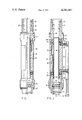
FIG. 1 is a longitudinal sectional view through an exemplary embodiment of apparatus for the Vo -measurement of a projectile fired from a weapon and illustrating part of the weapon barrel; and
FIG. 2 is a further longitudinal sectional view through the arrangement of FIG. 1 in a plane disposed at right angles to the first longitudinal sectional view of FIG. 1.
DETAILED DESCRIPTION OF THE PREFERRED EMBODIMENTS
Describing now the drawings, according to the showing of FIGS. 1 and 2 the inventive Vo -measuring apparatus will be seen to be secured to the muzzle or mouth of a weapon barrel 10 which only has been indicated in phantom lines and contains a connection piece or element 11. This connection element 11 is provided with internal threads 12 and can be threaded onto complementary but not particularly illustrated external threads of the weapon barrel 10. A slot 13 at the rear end of the connection element 11 enables securing the connection element 11 upon the weapon barrel 10 against unintentional rotation. At the connection element 11 there is attached with the aid of a bayonet joint or connection 14 or equivalent fastening device a tube or barrel member 15 which preferably is fabricated of steel. Placed internally of this tube or barrel member 15 is a sleeve member 16 formed of a nonmagnetisable material. At both ends of the sleeve member 16 there are arranged internally of the tube 15 a respective electrical measuring coil 17 and 18. Both of the measuring coils 17 and 18 are embedded in a related protective ring member 19 formed of titanium and having a substantially U-shaped cross-sectional configuration. To protect the measuring coils 17 and 18 against the action of the aggressive propellant gases there is further arranged a respective sealing ring 20 at both ends of the sleeve member 16. These sealing rings or seals 20 prevent that propellant gases can penetrate between the sleeve member 16 and the tube or barrel member 15. At the front end of the tube or tube member 15 there is secured with the aid of, for instance, a bayonet connection 21 or equivalent fastening device a muzzle brake 22. This muzzle brake 22 possesses a conical bore 24 and has a number of radial bores 23 through which the propellant gases can escape into the surroundings, and thus, exerts in conventional manner a braking action, i.e. partially takes-up the recoil of the weapon barrel.
According to the illustration of FIG. 2 connection wires 25 of both of the measuring coils 17 and 18 are guided through two sleeves 26 arranged radially with respect to the weapon lengthwise axis. At both of these sleeves 26 there is secured a tube or pipe 27 directed essentially parallel to the weapon axis. Through the tube 27 there are guided the connection wires or lines 25 into a cable 28 which is attached at the rear end of the tube 27 and possesses at its rear end a coupling element 29.
Since the entire measuring apparatus is heated by the hot propellant gas there is beneficially provided a temperature feeler or sensor 30 in the wall of the tube or barrel member 15. A not particularly illustrated connection wire of the temperature feeler 30 is likewise guided through the sleeve member 26 and the tube or pipe 27 into the cable 28.
Having now had the benefit of the description of the exemplary embodiment of measuring apparatus its mode of operation will be now considered and is as follows:
If a sabot projectile moves out of the muzzle of the weapon, such as a cannon barrel 10, into the sleeve member 16 then the sleeve member 16 prevents detachment of the sabot from the projectile or projectile body. The sabot and the projectile body first can separate from one another after departure out of the sleeve member 16 and the muzzle brake 22. However, the measurement of the muzzle velocity Vo of the projectile occurs during such time as the projectile is propelled through the sleeve member 16 of the Vo -measuring device, i.e. in other words before the sabot detaches from the projectile. Impairment of the Vo -measurement by the sabot which is in the process of detaching or has already detached from the projectile, is therefore prevented. When the projectile along with the sabot travels through the first measuring coil 17, then as is well known in this technology there is induced a signal voltage or measuring signal in this measuring coil 17 which is delivered by the connection wire or line 25 to a not particularly illustrated but conventional evaluation device. Upon passage of the projectile through the second measuring coil 18 there is induced in the same manner as was the case for the first measuring coil 17 a second signal voltage or measuring signal which is likewise delivered to the evaluation device by means of the connection wires 25. From the time difference between both of the signals and from the spacing of both measuring coils 17 and 18 from one another it is then possible to compute in conventional manner the velocity with which the projectile moves through both of the measuring coils 17 and 18.
Since the measuring apparatus is heated and elongated by the action of the hot propellant gases the spacing between both of the measuring coils 17 and 18 changes. With the aid of a temperature feeler or sensor 30 it is possible to take into account the temperature-dependent spacing of both measuring coils 17 and 18 during the computation of the muzzle velocity of a projectile.
So that both of the measuring coils 17 and 18 do not turn relative to one another i.e. remain in the desired relative rotational position with respect to one another, there are secured two bolts 31 and 32 or equivalent anti-rotating securing means in the wall of the tube or barrel member 15, these bolts 31 and 32 extending into not particularly referenced bores of the protective rings 19 formed of titanium. This arrangement also facilitates the assembly of the measuring apparatus.
While there are shown and described present preferred embodiments of the invention, it is to be distinctly understood that the invention is not limited thereto, but may be otherwise variously embodied and practiced within the scope of the following claims. ACCORDINGLY,

Claims (8)

What we claim is:
1. An apparatus for measuring the muzzle velocity of a projectile fired out of a weapon having a weapon barrel containing a lengthwise axis, especially a sabot projectile, wherein the measuring apparatus is capable of being secured to the muzzle of the weapon barrel, comprising:
two measuring coils;
each of said measuring coils having a measuring coil axis;
said two measuring coils being arranged in spaced relationship from one another such that the measuring coil axes substantially coincide with the weapon barrel axis;
a sleeve member having opposed ends;
said sleeve member possessing an internal diameter which is essentially the same as the internal diameter of the weapon barrel;
said sleeve member having an external diameter which is essentially the same as the internal diameter of the measuring coils; and
one of the measuring coils being arranged at the one opposed end of the sleeve member and the other measuring coil at the other opposed end of the sleeve member.
2. The apparatus as defined in claim 1, wherein:
a respective sealing ring is arranged at each opposed end of the sleeve member in order to protect the measuring coils against the action of propellant gases.
3. The apparatus as defined in claim 1, wherein:
said measuring apparatus has a front end region; and
a muzzle brake arranged at the front end region of said measuring apparatus.
4. The apparatus as defined in claim 3, further including:
a connection element adapted to be connected to the muzzle of the weapon by means of threading;
a barrel member;
means for connecting one end of said barrel member with said connection element;
means for connecting the other end of said barrel member with said muzzle brake; and
said sleeve member being arranged internally of said barrel member.
5. The apparatus as defined in claim 4, wherein:
each of said connecting means comprise bayonet-type connection means.
6. The apparatus as defined in claim 1, further including:
protective rings in which there are arranged both of said measuring coils; and
each of said protective rings having a substantially U-shaped cross-sectional configuration for receiving a related one of the measuring coils.
7. The apparatus as defined in claim 6, wherein:
each of said protective rings is formed of titanium.
8. The apparatus as defined in claim 4, further including:
temperature feeler means arranged in a wall of said barrel member in order to enable taking into account the temperature of the measuring apparatus during computation of the muzzle velocity of the projectile.
US06/235,660 1980-03-11 1981-02-17 Apparatus for measuring the muzzle velocity V-null of a projectile fired from a weapon Expired - Fee Related US4342961A (en)

Applications Claiming Priority (2)

Application Number Priority Date Filing Date Title
CH189680 1980-03-11
CH1896/80 1980-03-11

Publications (1)

Publication Number Publication Date
US4342961A true US4342961A (en) 1982-08-03

Family

ID=4221124

Family Applications (1)

Application Number Title Priority Date Filing Date
US06/235,660 Expired - Fee Related US4342961A (en) 1980-03-11 1981-02-17 Apparatus for measuring the muzzle velocity V-null of a projectile fired from a weapon

Country Status (3)

Country Link
US (1) US4342961A (en)
EP (1) EP0035802B1 (en)
DE (1) DE3160856D1 (en)

Cited By (13)

* Cited by examiner, † Cited by third party
Publication number Priority date Publication date Assignee Title
US4486710A (en) * 1982-09-08 1984-12-04 The United States Of America As Represented By The Secretary Of The Army Radio frequency coupled differential sensor coil for improved muzzle velocity measurements
US4672316A (en) * 1983-08-19 1987-06-09 Werkzeugmaschinenfabrik Oerlikon-Buhrle Ag Method for calibrating a muzzle velocity measuring device
US4677376A (en) * 1982-11-10 1987-06-30 Werkzeugmaschinenfabrik Oerlikon-Buhrle Ag Apparatus for measuring the muzzle velocity of a projectile fired from a weapon
US5659148A (en) * 1994-09-21 1997-08-19 Rheinmetall Industrie Gmbh Temperature detector for a gun barrel
US5827958A (en) * 1996-01-05 1998-10-27 Primex Technologies, Inc. Passive velocity data system
US6064196A (en) * 1997-12-31 2000-05-16 Aai Corporation Apparatus and method for calculating muzzle velocity
US6590386B1 (en) 2000-11-27 2003-07-08 Brass Eagle, Inc. Electronics system for use with projectile firing devices
CN102620600A (en) * 2012-03-31 2012-08-01 中国人民解放军济南军区72465部队 Gun-muzzle coil supporting skeleton of air-defense antiaircraft gun
CN102706216A (en) * 2012-03-31 2012-10-03 中国人民解放军济南军区72465部队 Connection structure for speed measurement device of gun muzzle of antiaircraft gun
US9600900B2 (en) 2013-03-27 2017-03-21 Nostromo Holdings, Llc Systems to measure yaw, spin and muzzle velocity of projectiles, improve fire control fidelity, and reduce shot-to-shot dispersion in both conventional and air-bursting programmable projectiles
US9879963B2 (en) 2013-03-27 2018-01-30 Nostromo Holdings, Llc Systems to measure yaw, spin and muzzle velocity of projectiles, improve fire control fidelity, and reduce shot-to-shot dispersion in both conventional and airbursting programmable projectiles
US10514234B2 (en) 2013-03-27 2019-12-24 Nostromo Holdings, Llc Method and apparatus for improving the aim of a weapon station, firing a point-detonating or an air-burst projectile
US11933585B2 (en) 2013-03-27 2024-03-19 Nostromo Holdings, Llc Method and apparatus for improving the aim of a weapon station, firing a point-detonating or an air-burst projectile

Families Citing this family (2)

* Cited by examiner, † Cited by third party
Publication number Priority date Publication date Assignee Title
US7798046B2 (en) * 2006-03-21 2010-09-21 Honeywell International Inc. Mortar blast attenuator diffuser
CN109490571B (en) * 2018-12-27 2023-10-17 衡磊科技集团股份有限公司 Dangerous gun is testing arrangement for shooting

Citations (4)

* Cited by examiner, † Cited by third party
Publication number Priority date Publication date Assignee Title
US2691761A (en) * 1948-02-03 1954-10-12 Jr Nicholas M Smith Microwave measuring of projectile speed
US3024453A (en) * 1958-10-02 1962-03-06 Maurice R Ransom Projectile sensing and indicating device
US3659201A (en) * 1969-08-12 1972-04-25 Oerlikon Buehrle Ag Apparatus for measuring the muzzle velocity of a projectile
CA950700A (en) * 1972-08-02 1974-07-09 William F. Slaght Projectile velocity acquisitioner

Family Cites Families (1)

* Cited by examiner, † Cited by third party
Publication number Priority date Publication date Assignee Title
GB965077A (en) * 1960-08-29 1964-07-29 Military Training Device Compa Improvements in a method of and apparatus for measuring the muzzle velocity of a projectile

Patent Citations (4)

* Cited by examiner, † Cited by third party
Publication number Priority date Publication date Assignee Title
US2691761A (en) * 1948-02-03 1954-10-12 Jr Nicholas M Smith Microwave measuring of projectile speed
US3024453A (en) * 1958-10-02 1962-03-06 Maurice R Ransom Projectile sensing and indicating device
US3659201A (en) * 1969-08-12 1972-04-25 Oerlikon Buehrle Ag Apparatus for measuring the muzzle velocity of a projectile
CA950700A (en) * 1972-08-02 1974-07-09 William F. Slaght Projectile velocity acquisitioner

Cited By (14)

* Cited by examiner, † Cited by third party
Publication number Priority date Publication date Assignee Title
US4486710A (en) * 1982-09-08 1984-12-04 The United States Of America As Represented By The Secretary Of The Army Radio frequency coupled differential sensor coil for improved muzzle velocity measurements
US4677376A (en) * 1982-11-10 1987-06-30 Werkzeugmaschinenfabrik Oerlikon-Buhrle Ag Apparatus for measuring the muzzle velocity of a projectile fired from a weapon
US4672316A (en) * 1983-08-19 1987-06-09 Werkzeugmaschinenfabrik Oerlikon-Buhrle Ag Method for calibrating a muzzle velocity measuring device
US5659148A (en) * 1994-09-21 1997-08-19 Rheinmetall Industrie Gmbh Temperature detector for a gun barrel
KR100639045B1 (en) * 1996-01-05 2007-05-14 제너럴 다이나믹스 올드넌스 앤드 텍티컬 시스템즈 인코포레이티드 Projectile velocity measurement system and velocity calculation method
US5827958A (en) * 1996-01-05 1998-10-27 Primex Technologies, Inc. Passive velocity data system
US6064196A (en) * 1997-12-31 2000-05-16 Aai Corporation Apparatus and method for calculating muzzle velocity
US6590386B1 (en) 2000-11-27 2003-07-08 Brass Eagle, Inc. Electronics system for use with projectile firing devices
CN102620600A (en) * 2012-03-31 2012-08-01 中国人民解放军济南军区72465部队 Gun-muzzle coil supporting skeleton of air-defense antiaircraft gun
CN102706216A (en) * 2012-03-31 2012-10-03 中国人民解放军济南军区72465部队 Connection structure for speed measurement device of gun muzzle of antiaircraft gun
US9600900B2 (en) 2013-03-27 2017-03-21 Nostromo Holdings, Llc Systems to measure yaw, spin and muzzle velocity of projectiles, improve fire control fidelity, and reduce shot-to-shot dispersion in both conventional and air-bursting programmable projectiles
US9879963B2 (en) 2013-03-27 2018-01-30 Nostromo Holdings, Llc Systems to measure yaw, spin and muzzle velocity of projectiles, improve fire control fidelity, and reduce shot-to-shot dispersion in both conventional and airbursting programmable projectiles
US10514234B2 (en) 2013-03-27 2019-12-24 Nostromo Holdings, Llc Method and apparatus for improving the aim of a weapon station, firing a point-detonating or an air-burst projectile
US11933585B2 (en) 2013-03-27 2024-03-19 Nostromo Holdings, Llc Method and apparatus for improving the aim of a weapon station, firing a point-detonating or an air-burst projectile

Also Published As

Publication number Publication date
EP0035802B1 (en) 1983-09-14
EP0035802A1 (en) 1981-09-16
DE3160856D1 (en) 1983-10-20

Similar Documents

Publication Publication Date Title
US4342961A (en) Apparatus for measuring the muzzle velocity V-null of a projectile fired from a weapon
US4938146A (en) Grenade-type projectile
US4677376A (en) Apparatus for measuring the muzzle velocity of a projectile fired from a weapon
US3019733A (en) Projectile construction
US3446147A (en) Casing for the sabot of a projectile
AU596749B2 (en) Improved perforating projectile
US4655411A (en) Means for reducing spread of shots in a weapon system
SE427694B (en) SPECIAL FOR TRAINING ENDAMELY USED FULL-CALIBRATED OVEN GRANGE
GB643736A (en) Improvements in or relating to ammunition projectiles
US4754704A (en) Propellant charge for the reduction of base eddying
CA2080316A1 (en) Practice Projectile
US4773331A (en) Connection arrangement between a sabot jacket and the sabot rear portion of a sabot projectile
US4524697A (en) Projectile arrangement for a weapon having a gun barrel
CA2190385C (en) Method and device for determining the disaggregation time of a programmable projectile
GB1605226A (en) Hollow charge liners
US4481886A (en) Hollow charge
FI66988B (en) HAOLPATRON MED RIKTAD SPRAENGVERKAN OCH FOERFARANDE FOER FRAMSTAELLNING AV EN METALLISK KON FOER HAOLPATRON
KR20140045937A (en) Apparatus and method for programming a projectile
US2672094A (en) Fuze
US4708065A (en) Full caliber training projectile
US4098190A (en) Training ammunition for mortars
US1861054A (en) Armor piercing projectile
DE102009011447B4 (en) Method for igniting a warhead of a grenade and vehicle
SE442912B (en) DEVICE FOR STORING THE ELECTRIC PIPE IN THE RECYCLING COAT OF A RUGE CALIBRATED ELECTRIC WEAPON
US5090328A (en) Spin stabilized projectile unit

Legal Events

Date Code Title Description
AS Assignment

Owner name: WERKZEUGMACHINENFABRIK OERLIKON-BUHRLE AG., BIRCHS

Free format text: ASSIGNMENT OF ASSIGNORS INTEREST.;ASSIGNORS:ZIMMERMANN JAKOB;KOCHER WILLI;REEL/FRAME:003867/0850

Effective date: 19810205

FEPP Fee payment procedure

Free format text: PAYOR NUMBER ASSIGNED (ORIGINAL EVENT CODE: ASPN); ENTITY STATUS OF PATENT OWNER: LARGE ENTITY

MAFP Maintenance fee payment

Free format text: PAYMENT OF MAINTENANCE FEE, 4TH YEAR, PL 96-517 (ORIGINAL EVENT CODE: M170); ENTITY STATUS OF PATENT OWNER: LARGE ENTITY

Year of fee payment: 4

FEPP Fee payment procedure

Free format text: MAINTENANCE FEE REMINDER MAILED (ORIGINAL EVENT CODE: REM.); ENTITY STATUS OF PATENT OWNER: LARGE ENTITY

LAPS Lapse for failure to pay maintenance fees
STCH Information on status: patent discontinuation

Free format text: PATENT EXPIRED DUE TO NONPAYMENT OF MAINTENANCE FEES UNDER 37 CFR 1.362

FP Lapsed due to failure to pay maintenance fee

Effective date: 19900805