US4337643A - Knock detecting apparatus for internal combustion engine - Google Patents
Knock detecting apparatus for internal combustion engine Download PDFInfo
- Publication number
- US4337643A US4337643A US06/211,296 US21129680A US4337643A US 4337643 A US4337643 A US 4337643A US 21129680 A US21129680 A US 21129680A US 4337643 A US4337643 A US 4337643A
- Authority
- US
- United States
- Prior art keywords
- core
- vibrating
- shaped
- knock
- rod
- Prior art date
- Legal status (The legal status is an assumption and is not a legal conclusion. Google has not performed a legal analysis and makes no representation as to the accuracy of the status listed.)
- Expired - Lifetime
Links
- 238000002485 combustion reaction Methods 0.000 title claims abstract description 9
- 239000000696 magnetic material Substances 0.000 claims abstract description 9
- 230000004907 flux Effects 0.000 claims description 19
- 235000014676 Phragmites communis Nutrition 0.000 claims description 17
- 244000273256 Phragmites communis Species 0.000 claims description 15
- 230000000149 penetrating effect Effects 0.000 claims 1
- 230000035945 sensitivity Effects 0.000 description 8
- 239000000463 material Substances 0.000 description 7
- 238000010276 construction Methods 0.000 description 6
- 238000001514 detection method Methods 0.000 description 5
- XEEYBQQBJWHFJM-UHFFFAOYSA-N Iron Chemical compound [Fe] XEEYBQQBJWHFJM-UHFFFAOYSA-N 0.000 description 4
- 230000003247 decreasing effect Effects 0.000 description 4
- 230000000694 effects Effects 0.000 description 4
- 230000007812 deficiency Effects 0.000 description 3
- 230000007613 environmental effect Effects 0.000 description 3
- 229910001030 Iron–nickel alloy Inorganic materials 0.000 description 2
- 238000005336 cracking Methods 0.000 description 2
- 238000004519 manufacturing process Methods 0.000 description 2
- 230000010287 polarization Effects 0.000 description 2
- 229910001369 Brass Inorganic materials 0.000 description 1
- 229910000640 Fe alloy Inorganic materials 0.000 description 1
- 230000001133 acceleration Effects 0.000 description 1
- 239000000853 adhesive Substances 0.000 description 1
- 230000001070 adhesive effect Effects 0.000 description 1
- 239000010951 brass Substances 0.000 description 1
- 238000001816 cooling Methods 0.000 description 1
- 230000006866 deterioration Effects 0.000 description 1
- 230000002542 deteriorative effect Effects 0.000 description 1
- 238000010586 diagram Methods 0.000 description 1
- -1 e.g. Substances 0.000 description 1
- 230000005284 excitation Effects 0.000 description 1
- 229910052742 iron Inorganic materials 0.000 description 1
- 230000007257 malfunction Effects 0.000 description 1
- 239000000203 mixture Substances 0.000 description 1
- 230000035939 shock Effects 0.000 description 1
- 229910000859 α-Fe Inorganic materials 0.000 description 1
Images
Classifications
-
- G—PHYSICS
- G01—MEASURING; TESTING
- G01L—MEASURING FORCE, STRESS, TORQUE, WORK, MECHANICAL POWER, MECHANICAL EFFICIENCY, OR FLUID PRESSURE
- G01L23/00—Devices or apparatus for measuring or indicating or recording rapid changes, such as oscillations, in the pressure of steam, gas, or liquid; Indicators for determining work or energy of steam, internal-combustion, or other fluid-pressure engines from the condition of the working fluid
- G01L23/22—Devices or apparatus for measuring or indicating or recording rapid changes, such as oscillations, in the pressure of steam, gas, or liquid; Indicators for determining work or energy of steam, internal-combustion, or other fluid-pressure engines from the condition of the working fluid for detecting or indicating knocks in internal-combustion engines; Units comprising pressure-sensitive members combined with ignitors for firing internal-combustion engines
- G01L23/221—Devices or apparatus for measuring or indicating or recording rapid changes, such as oscillations, in the pressure of steam, gas, or liquid; Indicators for determining work or energy of steam, internal-combustion, or other fluid-pressure engines from the condition of the working fluid for detecting or indicating knocks in internal-combustion engines; Units comprising pressure-sensitive members combined with ignitors for firing internal-combustion engines for detecting or indicating knocks in internal combustion engines
- G01L23/223—Devices or apparatus for measuring or indicating or recording rapid changes, such as oscillations, in the pressure of steam, gas, or liquid; Indicators for determining work or energy of steam, internal-combustion, or other fluid-pressure engines from the condition of the working fluid for detecting or indicating knocks in internal-combustion engines; Units comprising pressure-sensitive members combined with ignitors for firing internal-combustion engines for detecting or indicating knocks in internal combustion engines using magnetic or magnetostrictive means
Definitions
- the present invention relates to knock detecting apparatus for detecting the presence of knock in an internal combustion engine.
- Knock detecting apparatus of the above type are known in the art in which a piezoelectric acceleration detector including a piezoelectric element is used to detect the knock-induced vibrations of an engine.
- a piezoelectric element of the essentially high-impedance type Due to the use of a piezoelectric element of the essentially high-impedance type, its characteristics are subject to the effects of humidity and dirt and thus it is difficult to generate stably small trace-knock signals (due to large drift and vibration variations). Also, the piezoelectric characteristic of the element is determined by polarization, and thus due to the severe use conditions varying cyclically between the high and low temperature conditions the polarization tends to be lost gradually with the corresponding deterioration of the sensitivity. The decreased sensitivity results in a rise in the knock control level causing sometimes damages to the engine due to its knocking.
- the detector is constructed inexpensively.
- the piezoelectric element is a high-impedance device
- its output signal must be amplified by means of an expensive amplifier of the high-impedance input type which is called as a charge amplifier.
- the high-impedance type amplifier tends to malfunction due to the effect of noise or the like caused by the ignition signals of the engine, it is necessary to use a detector of more expensive and complicated construction to overcome the deficiency.
- the piezoelectric element When used as a vehicle detector, the piezoelectric element has many disadvantages in terms of durability, cost and the like such as lower resistance to shock, tendency to crack and break and necessity to use cooling means or the like when the detector is used in high temperature conditions.
- an improved knock detecting apparatus comprising a magnetic path including a vibrating means having a resonance characteristic with respect to those frequencies at which knock is caused and disposed to vibrate in at least two vibration directions, the magnetic path forming a gap between it and the vibrating means in each of the vibration directions, and magnetic flux sensing means.
- the resonance frequency of the vibrating means can be easily adjusted to knocking high frequencies so that the sensitivity of the vibrating means to the knocking frequencies can be increased remarkably and also the detecting sensitivity to the vibration noise inevitably generated from the engine body (e.g., the vibration noise due to valve seating) is relatively decreased, thus improving the S/N ratio and making possible the detection of low level knock.
- a coil, a magnet, etc. which are excellent in environmental resistance, to firmly support the vibrating means, to withstand sufficiently the severe use conditions of vehicles, to ensure stable operation without any danger of deteriorating the characteristic, to prevent cracking and breaking of the elements and to ensure a sufficient mechanical strength.
- the detection of knock signal can be effected by means of such magnetically sensitive element as a coil or magneto-resistance element forming low-impedance detecting means which is quite contrary to the high-impedance piezoelectric element, the detecting means is practically not subjected to the effect of humidity, etc., is highly stable in operation against electric noise such as ignition noise, is simple in construction and small in size and allows the use of an inexpensive material which is well suited for mass production purposes.
- FIG. 1 is a schematic block diagram showing the construction of a knock feedback ignition system incorporating a knock detecting apparatus according to the present invention.
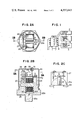
- FIGS. 2A, 2B and 2C show a first embodiment of the detecting apparatus according to the invention, with FIG. 2A showing a cross-sectional view taken along the line IIA--IIA of FIG. 2B, FIG. 2B a longitudinal sectional view taken along the line IIB--IIB of FIG. 2A, and FIG. 2C a side view showing the principal parts of the apparatus.
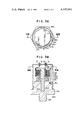
- FIGS. 3A and 3B show a second embodiment of the detecting apparatus according to the invention, with FIG. 3A showing a cross-sectional view taken along the line IIIA--IIIA of FIG. 3B and FIG. 3B showing a longitudinal sectional view taken along the line IIIB--IIIB of FIG. 3A.
- FIG. 1 there is illustrated the construction of a knock feedback ignition system incorporating a knock detecting apparatus according to the present invention.
- numeral 1 designates a four-cylinder in-line type internal combustion engine, and a knock detecting apparatus 2 is attached to the cylinder block of the engine 1 by means of a screw or the like.
- Numeral 3 designates a knock detecting circuit for detecting the engine knock from the output signal of the knock detecting apparatus 2, and 4 an ignition timing control unit responsive to the output of the knock detecting circuit 3 to advance or retard the ignition timing into the optimum position.
- the output signal of the control unit 4 is distributed through a known type of ignition device 5 to the spark plugs fitted into the engine 1 to ignite the mixture.
- the knock detecting circuit 3 used in this system detects an ignition signal which is not shown such that a noise component produced by the engine vibration during a predetermined time interval or a predetermined angle of crankshaft rotation immediately following the ignition where there is no occurrence of knock, is sampled by means of the output of the detecting apparatus 2 and then compared with the output of the detecting apparatus 2 (its integrated value or averaged value may sometimes be used) produced during a predetermined time interval or a predetermined crank angle after the top dead center (after the peak combustion pressure) where there is a high tendency to knock, thereby determining the presence of knock.
- the presence of knock can be determined in a probability manner instead of simply relying on a single signal.
- the presence of knock can be determined in terms of the percentage of knocking events occurring in 100 times of ignition.
- the ignition timing control unit 4 advances or retards the ignition timing in accordance with the presence or absence of knock. While the detailed constructions of the knock detecting circuit 3 and the ignition timing control unit 4 are well known in the art and will not be described, it should be apparent that the detecting apparatus of this invention can be used with these circuit and unit of any type provided that knock is detected and the ignition timing is controlled correspondingly.
- numeral 21 designates a vibrating member made from a magnetic material (e.g., iron or iron-nickel alloy) in rod form of a circular cross-sectional shape and having a resonance point or frequency within the knocking frequencies ranging from 5 to 10 kHz, and one end of the vibrating member 21 is secured by driving fit to a support member 22 made of a magnetic material.
- Numeral 23 designates a magnet having a magnetic force and magnetized in the polarity shown and its north pole side is in contact with the support member 22.
- Numeral 24 designates an L-shaped core made of a material, e.g., iron, iron-nickel alloy or ferrite and forming a magnetic path in association with the vibrating member 21, the support member 22 and the magnet 23.
- One end of the core 24 is in contact with the south pole of the magnet 23, and a hole 24a is formed through the other end of the core 24 such that the other end of the vibrating member 21 is inserted into the hole 24a substantially centrally to form a gap G therebetween.
- the gap G is defined as a ring shaped one between the core 24 and the vibrating member 21.
- Numeral 25 designates a coil forming magnetic flux sensing means for sensing a change in the magnetic flux caused by the reluctance change.
- the coil 25 is wound on the core 24 through the intermediary of a bobbin 25a and the bobbin 25a is secured to the core 24 by means of an adhesive or the like to prevent any variation of the flux linkage due to a change in the relative positions of the coil 25 and the core 24.
- Numeral 26 designates a housing made of a nonmagnetic material such as brass and including a threaded portion 26a formed in the lower part for screwing the apparatus into the cylinder block of the engine, a wrench hexagon portion 26b formed on the outer periphery and a recess 26c formed in the central part to receive the coil 25.
- Numeral 27 designates a keep member made of a nonmagnetic material and disposed to hold in place the previously mentioned members forming the magnetic path, and the keep member 27 is firmly secured, along with washers 28, to the housing 26 by means of screws 29 to hold down the support member 22, the magnet 23 and the core 24.
- Numeral 30 designates a cover attached by caulking to the housing 26, and fitted in the cover 30 is a hermetic seal 32 having terminals 31 firmly fitted therein for signal delivering purposes.
- the ends of the coil 25 are connected to the terminals 31 so that the coil ends are connected to the knock detecting circuit 3 through the terminals 31 and the external signal lines.
- the detecting apparatus 2 is attached to the cylinder block by firmly screwing the threaded portion 26a thereinto.
- the vibrations produced in the cylinder block upon the occurrence of knock are transmitted to the vibrating member 21 through the housing 26, the core 24, the magnet 23 and the support member 22. Since the vibrating member 21 has its one end firmly secured to the support member 22, the vibrating member 21 vibrates in accordance with the frequency and magnitude of the vibrations as well as the natural frequency of the vibrating member 21 itself.
- the vibrating member 21 since all the component parts excluding the vibrating member 21 are firmly attached to the housing 26 to move together therewith, the vibrating member 21 alone moves in the magnetic path so that the gap G formed into ring shape around the vibrating member 21 is varied and the reluctance of the magnetic path is varied correspondingly, thus generating in the coil 25 a voltage output corresponding to the magnetic flux change.
- This output signal is supplied to the detecting circuit 3 through the terminals 31 provided in the hermetic seal 32 and through the two signal lines.
- the materials and the spacing of the component parts are suitably selected such that the leakage flux becomes sufficiently small as compared with the flux flowing through the magnetic path, thus giving rise to no difficulty in the detection of knock.
- the resonance point of the vibrating member 21 is selected to come within the range of knocking frequencies (at around the middle of 5 to 10 kHz or 8 kHz), the knock detecting sensitivity is particularly increased at these frequencies and the sensitivity to signals in the other frequency ranges is relatively deteriorated, thus improving the S/N ratio in the knock detection.
- the vibrating member 21 is capable of detecting the vibrations generated in all the directions tending to vibrate the vibrating member 21 radially.
- the vibrations due to the knocking of an engine do not occur in one direction only and basically the knock-induced vibrations propagate in all the directions of the combustion chamber.
- the ring-shaped gap G is formed to surround all the outer surface of the end of the vibrating member 21
- the gap G needs not always be formed to surround all the outer surface of the end of the vibrating member 21 and a notch may be formed in the portion of the core 24 which is adjacent to the gap G.
- the cross-sectional shape of the vibrating member 21 needs not always be circular and it may be formed into any other shape such as square shape.
- FIGS. 3A and 3B show a second embodiment of the detecting apparatus 2.
- a ring magnet 23a which is magnetized in the vertical direction is arranged on a housing 26A made of a magnetic material, and a bobbin 25a having a coil 25 wound thereon is arranged on the magnet 23a.
- a hole is formed centrally through each of the bobbin 25a and the magnet 23A, and inserted into these center holes is a center core 24A made from a magnetic material and including a polygonal collar 24b at its upper end.
- a bar member 24B made of a nonmagnetic material is secured to the lower end of the core 24A.
- the bar member 24B is fixed by driving fit in a driving fit recess 26d formed in the central portion of the housing 26A and in this way the magnet 23A, the center core 24A and the coil 25 are firmly secured to the housing 26A.
- the upper end outer surface of the housing 26A is formed into a polygonal shape and a plurality (three) of vibrating reeds 21A to 21C forming a vibrating means each has its one end secured to one side of the polygonal upper end by a screw 28A.
- Each of the other ends of the vibrating reeds 21A to 21C is arranged to face the collar 24b of the center core 24A across a gap G.
- a magnetic path is formed comprising the north pole of the magnet 23A, the center core 24A, each of the vibrating reeds 21A to 21C, the housing 26A and the south pole of the magnetic 23A.
- the three vibrating reeds 21A to 21C are used, it is possible to use only two or more than four vibrating reeds depending on the number of angles included in the polygonal portion of the housing 26A and in the polygonal collar 24b. Also, while, in FIG. 3, vibrating reeds may be provided at the opposite positions to the vibrating reeds 21A to 21C, this is not desirable since the opposite gap G of each vibrating reed varies in width in the opposite direction and the resulting reluctance change due to the vibration of the vibrating reed is decreased.
- the magnetic flux sensing means comprises the coil 25, it is possible to use a magneto-resistance element or a Hall device.
- the magnets 23 and 23A are used as a means for supplying magnetic flux to the magnetic path
- an excitation coil wound on the magnetic path it is possible to use an excitation coil wound on the magnetic path.
- the coil 25 by connecting the coil 25 to an oscillator such that a change in the reluctance of the magnetic path due to the vibration of the vibrating member 21 or the vibrating reeds 21A to 21C is sensed as a change in the load of the oscillator, it is possible to eliminate the need to use any special means for supplying magnetic flux to the magnetic path.
- the sensing means of the detecting apparatus is operated magnetically and that the component parts of the apparatus include a coil, a magnet, etc., which are excellent in environmental resistance and having sufficient resistance to the severe environmental conditions of vehicles, the detecting apparatus is less likely to give rise to such deficiencies as encountered with the piezoelectric element, that is, the signal drift due to humidity, the breaking and cracking of the element, etc., and moreover the apparatus not only has a sufficient mechanical strength but also is capable of generating a stable output.
- the coil or the magneto-resistance element has an impedance which is considerably lower than that of the piezoelectric element, is less susceptible to the effect of ignition noise, etc., does not require the use of a charge amplifier as the amplifier, is not subject to the leakage of charge due to dirt and humidity and low in cost and has an excellent stability.
- Another great advantage is that the required material is not so high in cost as the piezoelectric element and excellent in terms of mass production properties and durability, and thus the apparatus is highly efficient, low in cost, excellent in durability and capable of detecting such light knock as trace knock.
Landscapes
- Chemical & Material Sciences (AREA)
- Engineering & Computer Science (AREA)
- Combustion & Propulsion (AREA)
- Physics & Mathematics (AREA)
- General Physics & Mathematics (AREA)
- Measurement Of Mechanical Vibrations Or Ultrasonic Waves (AREA)
- Electrical Control Of Ignition Timing (AREA)
- Combined Controls Of Internal Combustion Engines (AREA)
Applications Claiming Priority (2)
| Application Number | Priority Date | Filing Date | Title |
|---|---|---|---|
| JP54-155765 | 1979-11-30 | ||
| JP15576579A JPS5679215A (en) | 1979-11-30 | 1979-11-30 | Knocking detector for internal combustion engine |
Publications (1)
| Publication Number | Publication Date |
|---|---|
| US4337643A true US4337643A (en) | 1982-07-06 |
Family
ID=15612912
Family Applications (1)
| Application Number | Title | Priority Date | Filing Date |
|---|---|---|---|
| US06/211,296 Expired - Lifetime US4337643A (en) | 1979-11-30 | 1980-11-28 | Knock detecting apparatus for internal combustion engine |
Country Status (2)
| Country | Link |
|---|---|
| US (1) | US4337643A (enExample) |
| JP (1) | JPS5679215A (enExample) |
Cited By (2)
| Publication number | Priority date | Publication date | Assignee | Title |
|---|---|---|---|---|
| US20050274189A1 (en) * | 2004-06-11 | 2005-12-15 | Denso Corporation | Pressure-detecting device and method of manufacturing the same |
| US20070256764A1 (en) * | 2005-08-25 | 2007-11-08 | Qingyou Han | Method of producing nanostructured metals using high-intensity ultrasonic vibration |
Citations (3)
| Publication number | Priority date | Publication date | Assignee | Title |
|---|---|---|---|---|
| US4096735A (en) * | 1977-02-11 | 1978-06-27 | General Motors Corporation | Engine detonation sensor with double shielded case |
| US4108006A (en) * | 1976-03-30 | 1978-08-22 | Johnson, Matthey & Co., Limited | Accelerometers |
| US4275586A (en) * | 1978-01-18 | 1981-06-30 | Robert Bosch Gmbh | Oscillation sensor, particularly combustion engine knock sensor |
-
1979
- 1979-11-30 JP JP15576579A patent/JPS5679215A/ja active Granted
-
1980
- 1980-11-28 US US06/211,296 patent/US4337643A/en not_active Expired - Lifetime
Patent Citations (3)
| Publication number | Priority date | Publication date | Assignee | Title |
|---|---|---|---|---|
| US4108006A (en) * | 1976-03-30 | 1978-08-22 | Johnson, Matthey & Co., Limited | Accelerometers |
| US4096735A (en) * | 1977-02-11 | 1978-06-27 | General Motors Corporation | Engine detonation sensor with double shielded case |
| US4275586A (en) * | 1978-01-18 | 1981-06-30 | Robert Bosch Gmbh | Oscillation sensor, particularly combustion engine knock sensor |
Cited By (3)
| Publication number | Priority date | Publication date | Assignee | Title |
|---|---|---|---|---|
| US20050274189A1 (en) * | 2004-06-11 | 2005-12-15 | Denso Corporation | Pressure-detecting device and method of manufacturing the same |
| US7191658B2 (en) * | 2004-06-11 | 2007-03-20 | Denso Corporation | Pressure-detecting device and method of manufacturing the same |
| US20070256764A1 (en) * | 2005-08-25 | 2007-11-08 | Qingyou Han | Method of producing nanostructured metals using high-intensity ultrasonic vibration |
Also Published As
| Publication number | Publication date |
|---|---|
| JPS5679215A (en) | 1981-06-29 |
| JPS624647B2 (enExample) | 1987-01-31 |
Similar Documents
| Publication | Publication Date | Title |
|---|---|---|
| US4345558A (en) | Knock detecting apparatus for an internal combustion engine | |
| US4371804A (en) | Piezoelectric knock sensor | |
| US4096735A (en) | Engine detonation sensor with double shielded case | |
| US2319219A (en) | Pressure indicating apparatus | |
| CA2488967A1 (en) | Eddy current sensors | |
| US4290301A (en) | Knock detecting apparatus for internal combustion engine | |
| US20050056087A1 (en) | Spark generating apparatus having strain gage cylinder pressure measurement feature | |
| US4341189A (en) | Knock detecting apparatus for combustion engines | |
| US4448059A (en) | Engine vibration sensor | |
| US4316440A (en) | Knock detecting apparatus for internal combustion engine | |
| JPS6337884B2 (enExample) | ||
| US6212944B1 (en) | Apparatus and method for monitoring engine conditions, using magnetostrictive sensors | |
| US4319480A (en) | Knock detector device for internal combustion engines | |
| US2619605A (en) | Vibration or impact indicator | |
| US20030155911A1 (en) | Tunable magnetic device for use in a proximity sensor | |
| US2435031A (en) | Detonation pickup | |
| US4337643A (en) | Knock detecting apparatus for internal combustion engine | |
| US4357825A (en) | Knock detecting apparatus for internal combustion engines | |
| US2445318A (en) | Magnetostrictive pickup unit | |
| US4462247A (en) | Knock detecting apparatus for internal combustion engines | |
| US4424705A (en) | Engine knock sensing apparatus | |
| US4336707A (en) | Knock detecting apparatus for internal combustion engines | |
| US4736620A (en) | Magnetostrictive element for measuring knock in engines | |
| US4379403A (en) | Knock detecting apparatus for internal combustion engines | |
| US4414840A (en) | Knock detecting apparatus for internal combustion engines |
Legal Events
| Date | Code | Title | Description |
|---|---|---|---|
| STCF | Information on status: patent grant |
Free format text: PATENTED CASE |