US4336128A - Combustion of pyrolyzed carbon containing solids in staged turbulent bed - Google Patents
Combustion of pyrolyzed carbon containing solids in staged turbulent bed Download PDFInfo
- Publication number
- US4336128A US4336128A US06/268,938 US26893881A US4336128A US 4336128 A US4336128 A US 4336128A US 26893881 A US26893881 A US 26893881A US 4336128 A US4336128 A US 4336128A
- Authority
- US
- United States
- Prior art keywords
- combustion zone
- solids
- particles
- phase combustion
- dense phase
- Prior art date
- Legal status (The legal status is an assumption and is not a legal conclusion. Google has not performed a legal analysis and makes no representation as to the accuracy of the status listed.)
- Expired - Lifetime
Links
- 239000007787 solid Substances 0.000 title claims abstract description 35
- OKTJSMMVPCPJKN-UHFFFAOYSA-N Carbon Chemical compound [C] OKTJSMMVPCPJKN-UHFFFAOYSA-N 0.000 title claims abstract description 15
- 229910052799 carbon Inorganic materials 0.000 title claims abstract description 15
- 238000002485 combustion reaction Methods 0.000 title claims description 61
- 238000000034 method Methods 0.000 claims abstract description 27
- 239000000463 material Substances 0.000 claims abstract description 14
- 238000012546 transfer Methods 0.000 claims abstract description 10
- 239000002245 particle Substances 0.000 claims description 51
- 239000007789 gas Substances 0.000 claims description 39
- 239000004058 oil shale Substances 0.000 claims description 21
- 239000003575 carbonaceous material Substances 0.000 claims description 7
- 239000000203 mixture Substances 0.000 claims description 5
- QVGXLLKOCUKJST-UHFFFAOYSA-N atomic oxygen Chemical compound [O] QVGXLLKOCUKJST-UHFFFAOYSA-N 0.000 claims description 4
- 230000001590 oxidative effect Effects 0.000 claims description 4
- 229910052760 oxygen Inorganic materials 0.000 claims description 4
- 239000001301 oxygen Substances 0.000 claims description 4
- 239000000567 combustion gas Substances 0.000 claims description 2
- 239000010419 fine particle Substances 0.000 description 7
- 239000010880 spent shale Substances 0.000 description 7
- 239000011362 coarse particle Substances 0.000 description 5
- 238000004064 recycling Methods 0.000 description 5
- 239000003546 flue gas Substances 0.000 description 4
- 238000000197 pyrolysis Methods 0.000 description 4
- 238000000926 separation method Methods 0.000 description 4
- UGFAIRIUMAVXCW-UHFFFAOYSA-N Carbon monoxide Chemical compound [O+]#[C-] UGFAIRIUMAVXCW-UHFFFAOYSA-N 0.000 description 3
- 238000011067 equilibration Methods 0.000 description 3
- XEEYBQQBJWHFJM-UHFFFAOYSA-N Iron Chemical compound [Fe] XEEYBQQBJWHFJM-UHFFFAOYSA-N 0.000 description 2
- VYPSYNLAJGMNEJ-UHFFFAOYSA-N Silicium dioxide Chemical compound O=[Si]=O VYPSYNLAJGMNEJ-UHFFFAOYSA-N 0.000 description 2
- 239000012876 carrier material Substances 0.000 description 2
- 230000001419 dependent effect Effects 0.000 description 2
- 238000005243 fluidization Methods 0.000 description 2
- 238000002156 mixing Methods 0.000 description 2
- XLYOFNOQVPJJNP-UHFFFAOYSA-N water Substances O XLYOFNOQVPJJNP-UHFFFAOYSA-N 0.000 description 2
- 239000004215 Carbon black (E152) Substances 0.000 description 1
- 239000005909 Kieselgur Substances 0.000 description 1
- 229910000831 Steel Inorganic materials 0.000 description 1
- PNEYBMLMFCGWSK-UHFFFAOYSA-N aluminium oxide Inorganic materials [O-2].[O-2].[O-2].[Al+3].[Al+3] PNEYBMLMFCGWSK-UHFFFAOYSA-N 0.000 description 1
- 230000004888 barrier function Effects 0.000 description 1
- 239000000919 ceramic Substances 0.000 description 1
- 239000003245 coal Substances 0.000 description 1
- 238000013461 design Methods 0.000 description 1
- 239000012717 electrostatic precipitator Substances 0.000 description 1
- 230000007717 exclusion Effects 0.000 description 1
- 238000000605 extraction Methods 0.000 description 1
- 239000012530 fluid Substances 0.000 description 1
- -1 for example Substances 0.000 description 1
- 229930195733 hydrocarbon Natural products 0.000 description 1
- 150000002430 hydrocarbons Chemical class 0.000 description 1
- 239000011261 inert gas Substances 0.000 description 1
- 229910052742 iron Inorganic materials 0.000 description 1
- 238000012856 packing Methods 0.000 description 1
- 238000012545 processing Methods 0.000 description 1
- 238000011027 product recovery Methods 0.000 description 1
- 239000004576 sand Substances 0.000 description 1
- 239000003079 shale oil Substances 0.000 description 1
- 238000009491 slugging Methods 0.000 description 1
- 239000010959 steel Substances 0.000 description 1
- 230000000153 supplemental effect Effects 0.000 description 1
- 239000011275 tar sand Substances 0.000 description 1
Images
Classifications
-
- C—CHEMISTRY; METALLURGY
- C10—PETROLEUM, GAS OR COKE INDUSTRIES; TECHNICAL GASES CONTAINING CARBON MONOXIDE; FUELS; LUBRICANTS; PEAT
- C10G—CRACKING HYDROCARBON OILS; PRODUCTION OF LIQUID HYDROCARBON MIXTURES, e.g. BY DESTRUCTIVE HYDROGENATION, OLIGOMERISATION, POLYMERISATION; RECOVERY OF HYDROCARBON OILS FROM OIL-SHALE, OIL-SAND, OR GASES; REFINING MIXTURES MAINLY CONSISTING OF HYDROCARBONS; REFORMING OF NAPHTHA; MINERAL WAXES
- C10G1/00—Production of liquid hydrocarbon mixtures from oil-shale, oil-sand, or non-melting solid carbonaceous or similar materials, e.g. wood, coal
- C10G1/02—Production of liquid hydrocarbon mixtures from oil-shale, oil-sand, or non-melting solid carbonaceous or similar materials, e.g. wood, coal by distillation
Definitions
- the solid which remains is referred to as "pyrolyzed carbon containing material" or in the case of oil shale--"retorted oil shale".
- This solid contains carbonaceous residue which may be burned to yield heat energy. The heat recovered from the combustion may be used to supply heat for the pyrolysis of fresh oil shale or other carbonaceous material in the pyrolysis process.
- the burned shale serves as a "heat carrier material" to directly supply the heat for retorting of more raw oil shale.
- retorted shale is combusted in a separate vessel, and the hot, burned shale is recycled to the retorting vessel and mixed with the raw oil shale. Heat is transferred between the two solids, and the mixture reaches a uniform temperature. At this temperature the oil is released from the raw oil shale. See for example U.S. Pat. No. 4,199,432.
- the solids withdrawn from the retort and sent to the combustor are a mixture of freshly retorted shale and cooled recycle shale.
- the recycle shale contains little or no carbonaceous residue.
- the present invention is directed to an improved process for burning the pyrolyzed particulate carbon containing material and for separating out fine hot particles prior to recycling the remaining hot particles back into the pyrolysis vessel.
- the present invention concerns a process for producing heat from particulate pyrolyzed carbon containing solids containing a mixture of various size particles which comprises the steps of
- the process of this invention is particularly advantageous when the pyrolyzed carbon containing solid is retorted oil shale.
- the residual carbonaceous material in the retorted oil shale is partially burned prior to introduction into the dense phase combustion zone in a dilute phase combustion zone by entraining the oil shale particles in an entraining gas containing oxygen, said gas having a superficial velocity in excess of the terminal velocity of the particles of retorted oil shale.
- fine particles of burned shale or "fine fraction” refers to particles of a size unsuitable for recycling as heat transfer material. Usually particles smaller than about 100 to 200 mesh size (Tyler standard), i.e., about 75 to 150 microns in diameter, are not suitable for this purpose in the retorting process. Therefore, particles below this range are removed as entrained particles in the gas passing through the dense phase combustion zone.
- coarse fraction and “intermediate fraction” refer to particles larger than about 200 mesh size. It should be understood that the terms fine, intermediate and coarse are relative terms, the size of which may vary somewhat depending on the exact details of the process scheme. Thus, in process schemes where particles smaller than 200 mesh may be tolerated, the term “fines” may include particles of a smaller mesh size. Likewise, under other circumstances particles of larger minimum mesh size may be desired, and the definition of "fine particles” will be adjusted accordingly.
- intermediate refers to particles of a size which will fluidize, but not become entrained, when subjected to the countercurrent flow of gas passing through the dense phase combustion zone.
- coarse refers to particles too large to either fluidize or become entrained in a countercurrent flow of gas of a velocity equal to that being employed.
- Both the intermediate and coarse fractions pass downward with the moving bed of solids through the dense phase combustion zone in opposition to the direction of the gas flow.
- the dispersing elements serve to increase the residence time of the coarse particles to about 50-90% of the average residence time of all of the particles.
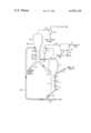
- the drawing is a schematic representation of an oil shale extraction process utilizing one embodiment of this invention.
- crushed raw oil shale is introduced into retort 1 via feed conduit 3.
- Recycled burned shale serving as heat transfer material is introduced into the retort through conduit 5.
- the lower portion 7 of the retort is equipped with multiple perforated plates 9, 11 and 13 which serve as dispersing elements.
- the upper portion 15 of retort 1 is of a larger diameter than the lower portion 7 in order to serve as a disengaging section for entrained solids.
- a stripping gas preferably steam or in some cases recycled product gas or other inert gas, is introduced into the bottom of the retort through conduit 17.
- the stripping gas and retorted oil vapors flow upward through the retort and are removed via conduit 19.
- Entrained fine particles of retorted oil shale are separated from the product vapors and stripping gas by a separation device 21.
- the separation device may be a hot cyclone, hot filter, electrostatic precipitator, or a combination of the described devices.
- the product vapors and stripping gas pass via conduit 23 into a product recovery zone 25 in which the shale oil and water are recovered.
- the oil is recovered for further processing through outlet 27 and water is withdrawn via conduit 29 for disposal and for recycling as steam.
- Product gas exits by way of outlet 31.
- solids are removed from the bottom of the lower portion 7 of the retort by means of conduit 33 and pass into a dilute phase combustion pipe 35 into which an entraining gas, usually air, is introduced by means of inlet 37.
- the carbonaceous residue in the retorted shale is partially burned in the dilute phase combustion pipe 35, raising the temperature of the entrained solids.
- the partially burned oil shale is discharged into a dense phase combustion chamber 39 having a lower portion 41 and an upper portion 43.
- the lower portion contains multiple perforated plates 45, 47, and 49 which serve as dispersing elements.
- dispersing elements limit gross vertical backmixing of the solids, limit slugging, and increase the residence time of the nonfluidizable coarse particles passing through the combustion chamber.
- the presence of the dispersing elements increases the residence time of the nonfluidizable particles to between about 50-90% of the average residence time for all particles passing through the dense phase combustion chamber.
- Air and entrained fine particles of retorted shale from separation device 21 are introduced into the lower portion 41 of the dense phase combustion chamber 39 by way of conduit 51.
- Conduit 51 preferably is sized so that some combustion of the entrained particles occurs prior to entry into the lower portion 41 of the dense phase combustion chamber.
- the air from conduit 51 passes upward in countercurrent flow to the downward moving bed of burning oil shale entraining fine particles of burned shale.
- the upper portion 43 of the combustion chamber serves as a disengager for entrained solids having a particle size larger than a preselected minimum.
- Flue gas carrying fine entrained particles of burned shale pass via conduit 53 to separation device 55 where the fines are separated from the flue gas.
- Intermediate and coarse particles of burned shale are recycled by way of conduit 5 back into retort 1. Burned shale in excess of that needed for recycle is disposed of through outlet 57.
- Retorted shale and recycled burned shale entering the dilute phase combustion zone are pneumatically entrained in a gas stream, usually air, and part of the residual carbonaceous material remaining in the shale is burned.
- Shale particles entering the dilute phase combustion chamber generally contain a wide range of particle sizes. In processes using recycled burned shale as a heat transfer material, maximum particle size may be about 1/4 inch.
- the entraining gas should have a velocity in the range of from about 50 feet per second to about 150 feet per second with a preferred range being of from about 80 feet per second to about 100 feet per second.
- the chamber (usually a liftpipe) need only be long enough to carry out the desired degree of combustion and temperature equilibration between the recycle shale and the burning retorted shale.
- the liftpipe must be long enough to raise the burning shale to the level of the inlet into the dense phase combustion zone.
- the shale moves through the dense phase combustion zone as a downward moving bed of material partially fluidized by a countercurrent flow of gas.
- These particles having a minimum fluidization velocity greater than the velocity of the countercurrent gas flow will pass downward in this combustion zone at a somewhat faster rate than the fluidized particles.
- Fine particles having a terminal velocity less than the velocity of the countercurrent gas flow will be entrained and carried upward with the gas.
- minimum fluidization velocity refers to the minimum superficial velocity of a gas passing through a bed of particles of given size required to cause the bed to behave like a fluid.
- Terminal velocity refers to the maximum velocity attained by a particle falling in a very long column of stagnant air.
- Entrained particle refers to a particle subjected to a gas flow whose velocity is in excess of the particle's terminal velocity.
- An essential feature of the dense phase combustion zone lies in limiting the maximum bubble size in the gas phase and limiting vertical backmixing of the downward moving shale to produce stable, substantially plug flow conditions of both gas and solids through this zone.
- An advantage of this design is that relatively uniform residence times for all particle sizes are achieved in the combustion zone. This assures substantially complete combustion of the carbonaceous residue and thermal equilibration between the hot burning particles and the cooler recycle particles. Residence times measured in minutes, rather than seconds (characteristic of the dilute phase section), are attainable.
- dispersing elements for substantially limiting gross vertical backmixing of the solids also permits a reduction in the size of the combustion zone required for a given mass throughput, since the chance for removing partially burned shale with the completely burned shale is reduced.
- the dispersing elements for limiting bubble size and increasing the residence time of the coarse particles may take the form of barriers or flow distributors and may, for example, include spaced horizontal perforated plates, bars, screens, packing, or other suitable internals.
- the preferred way of carrying out combustion in the dense phase combustion zone is by using air, or another oxygen containing gas, to supply the countercurrent gas flow.
- Combustion is preferably carried out in the super-stoichiometric mode, i.e., more than sufficient oxygen is present to insure complete combustion of the residual carbonaceous material.
- the velocity of the upward gas flow is usually in the range of from about 1 foot per second to about 5 feet per second and preferably in range of from about 1 to about 3 feet per second. This velocity is sufficient to entrain fine particles of about 200 mesh or smaller and carry them out of the top of the combustion zone along with the flue gas. Larger particles (intermediate and coarse sizes) are removed from the bottom of the combustion zone for recycling and for disposal.
- the process of this invention is most advantageously used in an oil shale retorting process using recycled burned shale as a heat transfer material, the process is not limited to that mode of operation.
- the process herein described can also be used to heat other types of heat transfer material such as, for example, ceramic compositions, sand, alumina, iron, steel and the like. Even in processes using burned shale as the principal heat transfer material, it is often necessary to add supplemental heat transfer material to the system.
- the hot flue gases exiting the top of the dense phase combustion zone could be used in retorting raw oil shale if such is desired, or alternatively the combustion could be also used to produce steam.
- various alternative embodiments and permutations of the invention may be conceived by one skilled in the art.
Abstract
Description
Claims (12)
Priority Applications (8)
| Application Number | Priority Date | Filing Date | Title |
|---|---|---|---|
| US06/268,938 US4336128A (en) | 1981-06-01 | 1981-06-01 | Combustion of pyrolyzed carbon containing solids in staged turbulent bed |
| CA000397715A CA1174524A (en) | 1981-06-01 | 1982-03-05 | Combustion of pyrolyzed carbon containing solids in a staged turbulent bed |
| ZA821522A ZA821522B (en) | 1981-06-01 | 1982-03-08 | Combustion of pyrolyzed carbon containing solids in a staged turbulent bed |
| AU81729/82A AU549655B2 (en) | 1981-06-01 | 1982-03-19 | Combustion of pyrolyzed carbon containing solids in staged turbulent bed |
| DE3218967A DE3218967A1 (en) | 1981-06-01 | 1982-05-19 | METHOD FOR GENERATING HEAT FROM SOLID PYROLYSIZED CARBON-SOLID PARTICLES |
| FR8208944A FR2506896B1 (en) | 1981-06-01 | 1982-05-24 | METHOD FOR PRODUCING HEAT FROM CARBON PYROLYSIS IN PARTICLES |
| GB08215186A GB2102107B (en) | 1981-06-01 | 1982-05-25 | Combustion of pyrolyzed carbon containing solids in staged turbulent bed |
| BR8203136A BR8203136A (en) | 1981-06-01 | 1982-05-28 | PROCESS TO PRODUCE HEAT WITH SOLIDS IN PIROLIZED PARTICLES CONTAINING CARBON |
Applications Claiming Priority (1)
| Application Number | Priority Date | Filing Date | Title |
|---|---|---|---|
| US06/268,938 US4336128A (en) | 1981-06-01 | 1981-06-01 | Combustion of pyrolyzed carbon containing solids in staged turbulent bed |
Publications (1)
| Publication Number | Publication Date |
|---|---|
| US4336128A true US4336128A (en) | 1982-06-22 |
Family
ID=23025154
Family Applications (1)
| Application Number | Title | Priority Date | Filing Date |
|---|---|---|---|
| US06/268,938 Expired - Lifetime US4336128A (en) | 1981-06-01 | 1981-06-01 | Combustion of pyrolyzed carbon containing solids in staged turbulent bed |
Country Status (8)
| Country | Link |
|---|---|
| US (1) | US4336128A (en) |
| AU (1) | AU549655B2 (en) |
| BR (1) | BR8203136A (en) |
| CA (1) | CA1174524A (en) |
| DE (1) | DE3218967A1 (en) |
| FR (1) | FR2506896B1 (en) |
| GB (1) | GB2102107B (en) |
| ZA (1) | ZA821522B (en) |
Cited By (25)
| Publication number | Priority date | Publication date | Assignee | Title |
|---|---|---|---|---|
| US4389950A (en) * | 1981-03-23 | 1983-06-28 | Chevron Research Company | Process for burning retorted oil shale and improved combustor |
| US4404083A (en) * | 1981-08-17 | 1983-09-13 | Standard Oil Company(Indiana) | Fluid bed retorting process and system |
| US4440623A (en) * | 1982-08-30 | 1984-04-03 | Chevron Research Company | Recycle classifier for retorting oil shale |
| US4481080A (en) * | 1983-05-13 | 1984-11-06 | The United States Of America As Represented By The United States Department Of Energy | Staged fluidized bed |
| US4495058A (en) * | 1983-06-06 | 1985-01-22 | Chevron Research Company | Process for generating superheated steam using retorted solids |
| US4539917A (en) * | 1983-09-21 | 1985-09-10 | The United States Of America As Represented By The United States Department Of Energy | Combustion heater for oil shale |
| US4544478A (en) * | 1982-09-03 | 1985-10-01 | Chevron Research Company | Process for pyrolyzing hydrocarbonaceous solids to recover volatile hydrocarbons |
| US4578175A (en) * | 1984-04-02 | 1986-03-25 | Conoco Inc. | Combined process for coal pyrolysis and char gasification |
| US4601812A (en) * | 1985-01-07 | 1986-07-22 | Conoco Inc. | Oil shale retorting process |
| US4619738A (en) * | 1983-09-21 | 1986-10-28 | The United States Of America As Represented By The United States Department Of Energy | Apparatus for oil shale retorting |
| US20110123407A1 (en) * | 2007-11-20 | 2011-05-26 | Ensyn Rewables, Inc. | Rapid thermal conversion of biomass |
| US20120137939A1 (en) * | 2010-12-06 | 2012-06-07 | Uop Llc | Processes and systems for producing heat for rapid thermal processing of carbonaceous material |
| US9044727B2 (en) | 2011-09-22 | 2015-06-02 | Ensyn Renewables, Inc. | Apparatuses and methods for controlling heat for rapid thermal processing of carbonaceous material |
| US9102888B2 (en) | 2011-12-12 | 2015-08-11 | Ensyn Renewables, Inc. | Methods for renewable fuels with reduced waste streams |
| US9127208B2 (en) | 2006-04-03 | 2015-09-08 | Pharmatherm Chemicals, Inc. | Thermal extraction method and product |
| US9347005B2 (en) | 2011-09-13 | 2016-05-24 | Ensyn Renewables, Inc. | Methods and apparatuses for rapid thermal processing of carbonaceous material |
| US9422478B2 (en) | 2010-07-15 | 2016-08-23 | Ensyn Renewables, Inc. | Char-handling processes in a pyrolysis system |
| US9441887B2 (en) | 2011-02-22 | 2016-09-13 | Ensyn Renewables, Inc. | Heat removal and recovery in biomass pyrolysis |
| US9670413B2 (en) | 2012-06-28 | 2017-06-06 | Ensyn Renewables, Inc. | Methods and apparatuses for thermally converting biomass |
| US9951278B2 (en) | 2010-05-20 | 2018-04-24 | Ensyn Renewables, Inc. | Processes for controlling afterburn in a reheater and for controlling loss of entrained solid particles in combustion product flue gas |
| US10041667B2 (en) | 2011-09-22 | 2018-08-07 | Ensyn Renewables, Inc. | Apparatuses for controlling heat for rapid thermal processing of carbonaceous material and methods for the same |
| US10337726B2 (en) | 2015-08-21 | 2019-07-02 | Ensyn Renewables, Inc. | Liquid biomass heating system |
| US10400175B2 (en) | 2011-09-22 | 2019-09-03 | Ensyn Renewables, Inc. | Apparatuses and methods for controlling heat for rapid thermal processing of carbonaceous material |
| US10400176B2 (en) | 2016-12-29 | 2019-09-03 | Ensyn Renewables, Inc. | Demetallization of liquid biomass |
| US10633606B2 (en) | 2012-12-10 | 2020-04-28 | Ensyn Renewables, Inc. | Systems and methods for renewable fuel |
Citations (3)
| Publication number | Priority date | Publication date | Assignee | Title |
|---|---|---|---|---|
| US4148710A (en) * | 1977-06-13 | 1979-04-10 | Occidental Oil Shale, Inc. | Fluidized bed process for retorting oil shale |
| US4199432A (en) * | 1978-03-22 | 1980-04-22 | Chevron Research Company | Staged turbulent bed retorting process |
| US4243489A (en) * | 1978-11-13 | 1981-01-06 | Occidental Petroleum Corp. | Pyrolysis reactor and fluidized bed combustion chamber |
Family Cites Families (1)
| Publication number | Priority date | Publication date | Assignee | Title |
|---|---|---|---|---|
| GB706164A (en) * | 1951-10-31 | 1954-03-24 | Standard Oil Dev Co | Improvements in or relating to oil shale distillation |
-
1981
- 1981-06-01 US US06/268,938 patent/US4336128A/en not_active Expired - Lifetime
-
1982
- 1982-03-05 CA CA000397715A patent/CA1174524A/en not_active Expired
- 1982-03-08 ZA ZA821522A patent/ZA821522B/en unknown
- 1982-03-19 AU AU81729/82A patent/AU549655B2/en not_active Ceased
- 1982-05-19 DE DE3218967A patent/DE3218967A1/en not_active Withdrawn
- 1982-05-24 FR FR8208944A patent/FR2506896B1/en not_active Expired
- 1982-05-25 GB GB08215186A patent/GB2102107B/en not_active Expired
- 1982-05-28 BR BR8203136A patent/BR8203136A/en unknown
Patent Citations (3)
| Publication number | Priority date | Publication date | Assignee | Title |
|---|---|---|---|---|
| US4148710A (en) * | 1977-06-13 | 1979-04-10 | Occidental Oil Shale, Inc. | Fluidized bed process for retorting oil shale |
| US4199432A (en) * | 1978-03-22 | 1980-04-22 | Chevron Research Company | Staged turbulent bed retorting process |
| US4243489A (en) * | 1978-11-13 | 1981-01-06 | Occidental Petroleum Corp. | Pyrolysis reactor and fluidized bed combustion chamber |
Cited By (48)
| Publication number | Priority date | Publication date | Assignee | Title |
|---|---|---|---|---|
| US4389950A (en) * | 1981-03-23 | 1983-06-28 | Chevron Research Company | Process for burning retorted oil shale and improved combustor |
| US4404083A (en) * | 1981-08-17 | 1983-09-13 | Standard Oil Company(Indiana) | Fluid bed retorting process and system |
| US4440623A (en) * | 1982-08-30 | 1984-04-03 | Chevron Research Company | Recycle classifier for retorting oil shale |
| US4544478A (en) * | 1982-09-03 | 1985-10-01 | Chevron Research Company | Process for pyrolyzing hydrocarbonaceous solids to recover volatile hydrocarbons |
| US4481080A (en) * | 1983-05-13 | 1984-11-06 | The United States Of America As Represented By The United States Department Of Energy | Staged fluidized bed |
| US4495058A (en) * | 1983-06-06 | 1985-01-22 | Chevron Research Company | Process for generating superheated steam using retorted solids |
| US4539917A (en) * | 1983-09-21 | 1985-09-10 | The United States Of America As Represented By The United States Department Of Energy | Combustion heater for oil shale |
| US4619738A (en) * | 1983-09-21 | 1986-10-28 | The United States Of America As Represented By The United States Department Of Energy | Apparatus for oil shale retorting |
| US4578175A (en) * | 1984-04-02 | 1986-03-25 | Conoco Inc. | Combined process for coal pyrolysis and char gasification |
| US4601812A (en) * | 1985-01-07 | 1986-07-22 | Conoco Inc. | Oil shale retorting process |
| US9809564B2 (en) | 2006-04-03 | 2017-11-07 | Pharmatherm Chemicals, Inc. | Thermal extraction method and product |
| US9127208B2 (en) | 2006-04-03 | 2015-09-08 | Pharmatherm Chemicals, Inc. | Thermal extraction method and product |
| US20110123407A1 (en) * | 2007-11-20 | 2011-05-26 | Ensyn Rewables, Inc. | Rapid thermal conversion of biomass |
| US10544368B2 (en) | 2007-11-20 | 2020-01-28 | Ensyn Renewables, Inc. | Rapid thermal conversion of biomass |
| US8961743B2 (en) * | 2007-11-20 | 2015-02-24 | Ensyn Renewables, Inc. | Rapid thermal conversion of biomass |
| US9631145B2 (en) | 2007-11-20 | 2017-04-25 | Ensyn Renewables, Inc. | Rapid thermal conversion of biomass |
| US10563127B2 (en) | 2010-05-20 | 2020-02-18 | Ensyn Renewables, Inc. | Processes for controlling afterburn in a reheater and for controlling loss of entrained solid particles in combustion product flue gas |
| US9951278B2 (en) | 2010-05-20 | 2018-04-24 | Ensyn Renewables, Inc. | Processes for controlling afterburn in a reheater and for controlling loss of entrained solid particles in combustion product flue gas |
| US9422478B2 (en) | 2010-07-15 | 2016-08-23 | Ensyn Renewables, Inc. | Char-handling processes in a pyrolysis system |
| US20120137939A1 (en) * | 2010-12-06 | 2012-06-07 | Uop Llc | Processes and systems for producing heat for rapid thermal processing of carbonaceous material |
| US11028325B2 (en) | 2011-02-22 | 2021-06-08 | Ensyn Renewables, Inc. | Heat removal and recovery in biomass pyrolysis |
| US9441887B2 (en) | 2011-02-22 | 2016-09-13 | Ensyn Renewables, Inc. | Heat removal and recovery in biomass pyrolysis |
| US9347005B2 (en) | 2011-09-13 | 2016-05-24 | Ensyn Renewables, Inc. | Methods and apparatuses for rapid thermal processing of carbonaceous material |
| US10794588B2 (en) | 2011-09-22 | 2020-10-06 | Ensyn Renewables, Inc. | Apparatuses for controlling heat for rapid thermal processing of carbonaceous material and methods for the same |
| US10400175B2 (en) | 2011-09-22 | 2019-09-03 | Ensyn Renewables, Inc. | Apparatuses and methods for controlling heat for rapid thermal processing of carbonaceous material |
| US9044727B2 (en) | 2011-09-22 | 2015-06-02 | Ensyn Renewables, Inc. | Apparatuses and methods for controlling heat for rapid thermal processing of carbonaceous material |
| US10041667B2 (en) | 2011-09-22 | 2018-08-07 | Ensyn Renewables, Inc. | Apparatuses for controlling heat for rapid thermal processing of carbonaceous material and methods for the same |
| US9422485B2 (en) | 2011-12-12 | 2016-08-23 | Ensyn Renewables, Inc. | Method of trading cellulosic-renewable identification numbers |
| US9120988B2 (en) | 2011-12-12 | 2015-09-01 | Ensyn Renewables, Inc. | Methods to increase gasoline yield |
| US9120990B2 (en) | 2011-12-12 | 2015-09-01 | Ensyn Renewables, Inc. | Systems for fuels from biomass |
| US9127223B2 (en) | 2011-12-12 | 2015-09-08 | Ensyn Renewables, Inc. | Systems and methods for renewable fuel |
| US9109177B2 (en) | 2011-12-12 | 2015-08-18 | Ensyn Renewables, Inc. | Systems and methods for renewable fuel |
| US9102890B2 (en) | 2011-12-12 | 2015-08-11 | Ensyn Renewables, Inc. | Fluidized catalytic cracking apparatus |
| US9969942B2 (en) | 2011-12-12 | 2018-05-15 | Ensyn Renewables, Inc. | Systems and methods for renewable fuel |
| US9120989B2 (en) | 2011-12-12 | 2015-09-01 | Ensyn Renewables, Inc. | Generating cellulosic-renewable identification numbers in a refinery |
| US9410091B2 (en) | 2011-12-12 | 2016-08-09 | Ensyn Renewables, Inc. | Preparing a fuel from liquid biomass |
| US9127224B2 (en) | 2011-12-12 | 2015-09-08 | Ensyn Renewables, Inc. | External steam reduction method in a fluidized catalytic cracker |
| US10975315B2 (en) | 2011-12-12 | 2021-04-13 | Ensyn Renewables, Inc. | Systems and methods for renewable fuel |
| US9102889B2 (en) | 2011-12-12 | 2015-08-11 | Ensyn Renewables, Inc. | Fluidized catalytic cracker riser quench system |
| US9102888B2 (en) | 2011-12-12 | 2015-08-11 | Ensyn Renewables, Inc. | Methods for renewable fuels with reduced waste streams |
| US10570340B2 (en) | 2011-12-12 | 2020-02-25 | Ensyn Renewables, Inc. | Systems and methods for renewable fuel |
| US9670413B2 (en) | 2012-06-28 | 2017-06-06 | Ensyn Renewables, Inc. | Methods and apparatuses for thermally converting biomass |
| US10633606B2 (en) | 2012-12-10 | 2020-04-28 | Ensyn Renewables, Inc. | Systems and methods for renewable fuel |
| US10640719B2 (en) | 2013-06-26 | 2020-05-05 | Ensyn Renewables, Inc. | Systems and methods for renewable fuel |
| US10948179B2 (en) | 2015-08-21 | 2021-03-16 | Ensyn Renewables, Inc. | Liquid biomass heating system |
| US10337726B2 (en) | 2015-08-21 | 2019-07-02 | Ensyn Renewables, Inc. | Liquid biomass heating system |
| US10400176B2 (en) | 2016-12-29 | 2019-09-03 | Ensyn Renewables, Inc. | Demetallization of liquid biomass |
| US10982152B2 (en) | 2016-12-29 | 2021-04-20 | Ensyn Renewables, Inc. | Demetallization of liquid biomass |
Also Published As
| Publication number | Publication date |
|---|---|
| BR8203136A (en) | 1983-05-17 |
| CA1174524A (en) | 1984-09-18 |
| GB2102107A (en) | 1983-01-26 |
| DE3218967A1 (en) | 1982-12-16 |
| FR2506896B1 (en) | 1986-05-02 |
| AU8172982A (en) | 1982-12-09 |
| GB2102107B (en) | 1984-09-26 |
| ZA821522B (en) | 1983-01-26 |
| FR2506896A1 (en) | 1982-12-03 |
| AU549655B2 (en) | 1986-02-06 |
Similar Documents
| Publication | Publication Date | Title |
|---|---|---|
| US4336128A (en) | Combustion of pyrolyzed carbon containing solids in staged turbulent bed | |
| US4145274A (en) | Pyrolysis with staged recovery | |
| US4102773A (en) | Pyrolysis with cyclone burner | |
| US3703442A (en) | Method for the low-temperature distillation of finely granular bituminous materials which form a pulverulent residue in the process | |
| US4087347A (en) | Shale retorting process | |
| US3167494A (en) | Method for pyrolizing solid carbonaceous materials | |
| CA1098852A (en) | Process and apparatus to produce synthetic crude oil from tar sands | |
| US3004898A (en) | Shale retorting process | |
| US3976558A (en) | Method and apparatus for pyrolyzing oil shale | |
| US4507195A (en) | Coking contaminated oil shale or tar sand oil on retorted solid fines | |
| US4336127A (en) | Staged burning of retorted carbon-containing solids | |
| US2984602A (en) | Method and apparatus for stripping oil from oil shale | |
| US4125453A (en) | Spouted-bed shale retorting process | |
| US4377466A (en) | Process for staged combustion of retorted carbon containing solids | |
| US5008005A (en) | Integrated coke, asphalt and jet fuel production process and apparatus | |
| US4521292A (en) | Process for improving quality of pyrolysis oil from oil shales and tar sands | |
| US4336126A (en) | Process for burning retorted oil shale and improved combustor | |
| US4332669A (en) | Oil shale retorting process with raw shale preheat prior to pyrolysis | |
| US4152245A (en) | Separation of rock solids from heat carriers in an oil shale retorting process | |
| US4366046A (en) | Size separation of oil shale particles for efficient retorting | |
| US4392942A (en) | Modified staged turbulent bed process for retorting carbon containing solids | |
| US4402823A (en) | Supplemental pyrolysis and fines removal in a process for pyrolyzing a hydrocarbon-containing solid | |
| US2959284A (en) | Transporting and classifying fluid solids | |
| US4389950A (en) | Process for burning retorted oil shale and improved combustor | |
| SU850012A3 (en) | Method of redusing iron ore materials in bolling layer |
Legal Events
| Date | Code | Title | Description |
|---|---|---|---|
| AS | Assignment |
Owner name: CHEVRON RESEARCH COMPANY, SAN FRANCISCO, CA., A C Free format text: ASSIGNMENT OF ASSIGNORS INTEREST.;ASSIGNOR:TAMM, PAUL W.;REEL/FRAME:003893/0485 Effective date: 19810519 |
|
| STCF | Information on status: patent grant |
Free format text: PATENTED CASE |
|
| MAFP | Maintenance fee payment |
Free format text: PAYMENT OF MAINTENANCE FEE, 4TH YEAR, PL 96-517 (ORIGINAL EVENT CODE: M170); ENTITY STATUS OF PATENT OWNER: LARGE ENTITY Year of fee payment: 4 |
|
| FEPP | Fee payment procedure |
Free format text: PAYOR NUMBER ASSIGNED (ORIGINAL EVENT CODE: ASPN); ENTITY STATUS OF PATENT OWNER: LARGE ENTITY |
|
| MAFP | Maintenance fee payment |
Free format text: PAYMENT OF MAINTENANCE FEE, 8TH YEAR, PL 96-517 (ORIGINAL EVENT CODE: M171); ENTITY STATUS OF PATENT OWNER: LARGE ENTITY Year of fee payment: 8 |
|
| MAFP | Maintenance fee payment |
Free format text: PAYMENT OF MAINTENANCE FEE, 12TH YEAR, LARGE ENTITY (ORIGINAL EVENT CODE: M185); ENTITY STATUS OF PATENT OWNER: LARGE ENTITY Year of fee payment: 12 |