US4325564A - Bicycle trailer - Google Patents
Bicycle trailer Download PDFInfo
- Publication number
- US4325564A US4325564A US06/134,540 US13454080A US4325564A US 4325564 A US4325564 A US 4325564A US 13454080 A US13454080 A US 13454080A US 4325564 A US4325564 A US 4325564A
- Authority
- US
- United States
- Prior art keywords
- secured
- hitch
- bicycle
- trailer
- frame
- Prior art date
- Legal status (The legal status is an assumption and is not a legal conclusion. Google has not performed a legal analysis and makes no representation as to the accuracy of the status listed.)
- Expired - Lifetime
Links
- 229910052751 metal Inorganic materials 0.000 claims description 4
- 239000002184 metal Substances 0.000 claims description 4
- 238000003466 welding Methods 0.000 description 5
- 238000010276 construction Methods 0.000 description 3
- 238000003780 insertion Methods 0.000 description 2
- 230000037431 insertion Effects 0.000 description 2
- 230000004048 modification Effects 0.000 description 2
- 238000012986 modification Methods 0.000 description 2
- 229910000831 Steel Inorganic materials 0.000 description 1
- 229910052782 aluminium Inorganic materials 0.000 description 1
- XAGFODPZIPBFFR-UHFFFAOYSA-N aluminium Chemical compound [Al] XAGFODPZIPBFFR-UHFFFAOYSA-N 0.000 description 1
- 239000000969 carrier Substances 0.000 description 1
- 239000012141 concentrate Substances 0.000 description 1
- 230000008878 coupling Effects 0.000 description 1
- 238000010168 coupling process Methods 0.000 description 1
- 238000005859 coupling reaction Methods 0.000 description 1
- 230000005484 gravity Effects 0.000 description 1
- 238000000034 method Methods 0.000 description 1
- 230000008450 motivation Effects 0.000 description 1
- 230000035939 shock Effects 0.000 description 1
- 239000010959 steel Substances 0.000 description 1
Images

Classifications
-
- B—PERFORMING OPERATIONS; TRANSPORTING
- B62—LAND VEHICLES FOR TRAVELLING OTHERWISE THAN ON RAILS
- B62K—CYCLES; CYCLE FRAMES; CYCLE STEERING DEVICES; RIDER-OPERATED TERMINAL CONTROLS SPECIALLY ADAPTED FOR CYCLES; CYCLE AXLE SUSPENSIONS; CYCLE SIDE-CARS, FORECARS, OR THE LIKE
- B62K27/00—Sidecars; Forecars; Trailers or the like specially adapted to be attached to cycles
- B62K27/003—Trailers
- B62K27/006—Trailers having a single wheel
-
- B—PERFORMING OPERATIONS; TRANSPORTING
- B60—VEHICLES IN GENERAL
- B60D—VEHICLE CONNECTIONS
- B60D1/00—Traction couplings; Hitches; Draw-gear; Towing devices
-
- B—PERFORMING OPERATIONS; TRANSPORTING
- B62—LAND VEHICLES FOR TRAVELLING OTHERWISE THAN ON RAILS
- B62J—CYCLE SADDLES OR SEATS; AUXILIARY DEVICES OR ACCESSORIES SPECIALLY ADAPTED TO CYCLES AND NOT OTHERWISE PROVIDED FOR, e.g. ARTICLE CARRIERS OR CYCLE PROTECTORS
- B62J7/00—Luggage carriers
- B62J7/02—Luggage carriers characterised by the arrangement thereof on cycles
- B62J7/04—Luggage carriers characterised by the arrangement thereof on cycles arranged above or behind the rear wheel
Definitions
- the invention relates generally to bicycle trailers and, more particularly, but not by way of limitation, it relates to an improved construction of bicycle trailer having lighter weight and greater tracking ability.
- the present invention relates to improvements in construction of bicycle trailers which enables provision of a standardized hitch and trailer assembly that may be utilized with any of today's touring-type bicycles as well as most other types of bicycles.
- the hitch assembly is vertically pivotally mounted to the rear forks of the bicycle for pivotal affixure with a tongue assembly as secured to an elongated trailer frame.
- the elongated trailer frame is supported in the horizontal attitude by suitable trailer fork members and braces which, in turn, are supported rotatably on a standard sized bicycle wheel.
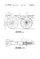
- FIG. 1 is a side elevation of the bicycle trailer and hitch assembly
- FIG. 2 is a top view of the bicycle trailer and hitch assembly
- FIG. 3 is a top plan view of a hitch T-connector as constructed in accordance with the present invention.
- FIG. 4 is a side view of the T-connector of FIG. 3;
- FIG. 5 is a top plan view of the hitch plate of the present invention.
- FIG. 6 is a top plan view of the tongue assembly of the present invention.
- FIG. 7 is a section taken along lines 7--7 of FIG. 6.
- the bicycle trailer 10 is pivotally secured for rear towing from a standard bicycle 12.
- the trailer 10 includes a horizontal, elongated frame 14 as supported on a standard bicycle wheel 16, and towing affixure is carried out by a tongue assembly 18 and hitch assembly 20 as vertically, pivotally secured to first and second T-connectors 22.
- the T-connectors 22 are suitably secured to the bicycle rear fork members 24 by such as tubing clamps, welding, etc.
- the support frame 14 may be formed from a single piece of steel or aluminum tubing to form parallel side rails 26 and 28 which are secured to opposite sides of tongue assembly 18, as will be further described. Suitable tubing cross pieces 30 are secured as by welding between side rails 26 and 28 to provide lateral rigidity.
- the load frame 14 is then supported by a bifurcated support structure including fork members 32 and 34, rear brace members 36 and 38, front brace members 40 and 42 and long braces 44 and 46.
- the opposed side fork members and brace members are secured as by welding to the underside of respective frame rails 26 and 28 wherein they terminate as secured at fork flanges 48 and 50 wherein an axle 52 of support wheel 16 is rotatably received.
- the long braces 44 and 46 are secured as by welding from respective front braces 40 and 42 to be secured beneath the forward portion of side rails 28 and 26.
- Each of the left and right T-connectors 22 are formed identically as illustrated in FIGS. 3 and 4.
- a central bar 54 is formed with one long edge having a half-round hollowed edge 56 for abutment against the bicycle fork members.
- a pair of identical flange plates 58, 60 having a securing eye 62 are then rigidly fastened centrally on opposite sides of bar 54 thereby to provide connector brackets for receiving the hitch assembly 20.
- the T-connectors 22 may be unitarily formed, or they may be formed utilizing one-half inch by 11/4 inch metal bar stock for the bar 54 and 1/4 inch by 1 inch metal bar stock for the flange plates 58 and 60 with suitable securing by means of pins 64, 66.
- T-connector 22 The half-round edge 56 of T-connector 22 is then placed in abutment to the bicycle rear fork member for clamping, and it is preferred that a padded hose-type clamp be utilized on each end of bar 54, thereby avoiding any marring or permanent disfiguration of the bicycle finish.
- FIG. 5 illustrates the hitch assembly 20 which is formed as a bifurcated hitch plate 58 having arms 70 and 72 and a hitch hole 74 formed centrally of the plate portion 68.
- the fork arm ends 70 and 72 are each tapped to receive the threaded rod ends 76 and 78 of the bearing rod ends 80 and 82, respectively.
- the threaded shaft bearing rod ends 80 and 82 are a commercially available type, AN 946-RE3MR3-"Self Aligning Ball Bearing Rod Ends".
- Each of the bearing rod ends 80 and 82 is then adapted for insertion between flange plates 58 and 60 of each of respective T-connectors 22L and 22R where a suitable fastener connection can be inserted, e.g. clevis pins 83 of other type rotatable fasteners.
- FIGS. 6 and 7 illustrate the tongue assembly 18 as it is formed on the forward end of frame side rails 26 and 28.
- Upper and lower tongue plates 84 and 86 are formed, preferably from a single piece of folded metal, and to include a lateral edge plate 88 which serves to provide additional transverse stiffening.
- the upper and lower tongue plate 84 and 86 are each formed with a semicircular end portion 90 having a hitch receiving hole 92 formed generally centrally in the semicircular end portion 90 of the plates.
- the side rail frames 26 and 28 are then secured as by welding along opposite sides 94 and 96. Semicircular cut out portions 98 and 100 in the back plate 88 will enable the side frames 26 and 28 to be led in for suitable securing affixure between tongue plates 84 and 86.
- the sides 94 and 96 of the tongue plate may be welded to side rails 26, 28 and a length of tubing 102 and angle tubes 104 and 106 are further secured between tongue plates 84 and 86 by means of spot welds 108, or like fastening techniques.
- the upper and lower tongue plates 84 and 86 are then adapted to be received above and below the spade portion 74 of hitch plate 58 with insertaion of a clevis pin 110 or like rotatable fastener through holes 92 and 74 to maintain the trailer 10 in proper tracking and trailing position.
- the T-connectors 22 are suitably secured to opposite rear fork members 24 and the bearing rod ends 80 and 82 are then pin-secured by means of pins 83 within the respective T-connectors 22L and 22R.
- the eye inserts of bearings 80 and 82 are capable of limited swivelling to enable easy alignment of the receiving holes and pin fasteners.
- the trailer 10 may be moved to slide tongue plates 84 and 86 over the hinge plate 68, and alignment of hinge hole 74 with tongue hole 92 enables insertion of the hitch pin 110, a suitable clevis pin or like arrangement.
- the bicycle 12 and trailer 10 are then in operative coupling for travel as the traveller's gear is affixed on horizontal frame 14.
- the biker may utilize various types of carriers such as standard bicycle panniers, saddle bags, wire side baskets and the like.
- larger items such as tents and sleeping bags may be easily secured on top of frame 14 by the use of shock cords or similar tying equipment.
- the carriage load may be centered directly over the trailer wheel 16 in such concentration as advantageous, and the trailer 10 will track in draft of the bicycle with least resistance to the biker's motivation efforts.
- the foregoing discloses a positive tracking bicycle trailer that exhibits considerable advantage over prior art forms of device.
- the trailer is optimally adjusted as to height and linearity to provide best center of gravity connection to the towing bicycle, and the trailer load is concentrated wholly on the trailer wheel without placing downward forces on the rear wheel of the bicycle.
- the particular structure contemplated allows use of high quality, light weight, efficient components having sufficient rugged characteristic for the particular usage.
- the trailer assembly has reduced frontal area to lessen wind resistance while also maintaining a lighter overall frame weight.
- the bicycle trailer of the present invention requires no modification to the towing bicycle and is readily usable on all 26 or 27 inch bicycles, i.e. the touring type bicycles.
Landscapes
- Engineering & Computer Science (AREA)
- Transportation (AREA)
- Mechanical Engineering (AREA)
- Fittings On The Vehicle Exterior For Carrying Loads, And Devices For Holding Or Mounting Articles (AREA)
Abstract
A bicycle trailer having reduced transverse profile and horizontal frame work with load carriage concentrated over the trailer wheel. The device utilizes a horizontal frame work as fork-supported above a standard bicycle wheel and having a tongue assembly formed integral with the trailer frame. The tongue assembly is then pivotally attached over a hitch plate that is vertically pivotally attached via T-connectors to each rear fork member of the associated bicycle.
Description
1. Field of the Invention
The invention relates generally to bicycle trailers and, more particularly, but not by way of limitation, it relates to an improved construction of bicycle trailer having lighter weight and greater tracking ability.
2. Description of the Prior Art
The prior art includes numerous types of bicycle trailers that have been used in the past for carrying various types of loads. United States patents known to be of particular interest are U.S. Pat. Nos. 2,404,362; 660,598; and 624,678. These prior art trailer types teach an entirely different form of frame structure and wheeling arrangements of distinguishable nature from the disclosure set forth hereinafter.
The present invention relates to improvements in construction of bicycle trailers which enables provision of a standardized hitch and trailer assembly that may be utilized with any of today's touring-type bicycles as well as most other types of bicycles. The hitch assembly is vertically pivotally mounted to the rear forks of the bicycle for pivotal affixure with a tongue assembly as secured to an elongated trailer frame. The elongated trailer frame is supported in the horizontal attitude by suitable trailer fork members and braces which, in turn, are supported rotatably on a standard sized bicycle wheel.
Therefore, it is an object of the present invention to provide a bicycle trailer which is light weight and durable of construction.
It is also an object of the present invention to provide an improved bicycle trailer having superior tracking capability to alleviate any dragging forces imposed on the bicycle.
Finally, it is an object of the present invention to provide a trailer that concentrates load weight on the trailer wheel and which requires no modification for use on all touring bicycles.
Other objects and advantages will be evident from the following detailed description when read in conjunction with the accompanying drawings which illustrate the invention.
FIG. 1 is a side elevation of the bicycle trailer and hitch assembly;
FIG. 2 is a top view of the bicycle trailer and hitch assembly;
FIG. 3 is a top plan view of a hitch T-connector as constructed in accordance with the present invention;
FIG. 4 is a side view of the T-connector of FIG. 3;
FIG. 5 is a top plan view of the hitch plate of the present invention;
FIG. 6 is a top plan view of the tongue assembly of the present invention; and,
FIG. 7 is a section taken along lines 7--7 of FIG. 6.
With reference to FIGS. 1 and 2, the bicycle trailer 10 is pivotally secured for rear towing from a standard bicycle 12. The trailer 10 includes a horizontal, elongated frame 14 as supported on a standard bicycle wheel 16, and towing affixure is carried out by a tongue assembly 18 and hitch assembly 20 as vertically, pivotally secured to first and second T-connectors 22. The T-connectors 22 are suitably secured to the bicycle rear fork members 24 by such as tubing clamps, welding, etc.
The support frame 14 may be formed from a single piece of steel or aluminum tubing to form parallel side rails 26 and 28 which are secured to opposite sides of tongue assembly 18, as will be further described. Suitable tubing cross pieces 30 are secured as by welding between side rails 26 and 28 to provide lateral rigidity. The load frame 14 is then supported by a bifurcated support structure including fork members 32 and 34, rear brace members 36 and 38, front brace members 40 and 42 and long braces 44 and 46. The opposed side fork members and brace members are secured as by welding to the underside of respective frame rails 26 and 28 wherein they terminate as secured at fork flanges 48 and 50 wherein an axle 52 of support wheel 16 is rotatably received. The long braces 44 and 46 are secured as by welding from respective front braces 40 and 42 to be secured beneath the forward portion of side rails 28 and 26.
Each of the left and right T-connectors 22 are formed identically as illustrated in FIGS. 3 and 4. Thus, a central bar 54 is formed with one long edge having a half-round hollowed edge 56 for abutment against the bicycle fork members. A pair of identical flange plates 58, 60 having a securing eye 62 are then rigidly fastened centrally on opposite sides of bar 54 thereby to provide connector brackets for receiving the hitch assembly 20. The T-connectors 22 may be unitarily formed, or they may be formed utilizing one-half inch by 11/4 inch metal bar stock for the bar 54 and 1/4 inch by 1 inch metal bar stock for the flange plates 58 and 60 with suitable securing by means of pins 64, 66. The half-round edge 56 of T-connector 22 is then placed in abutment to the bicycle rear fork member for clamping, and it is preferred that a padded hose-type clamp be utilized on each end of bar 54, thereby avoiding any marring or permanent disfiguration of the bicycle finish.
FIG. 5 illustrates the hitch assembly 20 which is formed as a bifurcated hitch plate 58 having arms 70 and 72 and a hitch hole 74 formed centrally of the plate portion 68. The fork arm ends 70 and 72 are each tapped to receive the threaded rod ends 76 and 78 of the bearing rod ends 80 and 82, respectively. The threaded shaft bearing rod ends 80 and 82 are a commercially available type, AN 946-RE3MR3-"Self Aligning Ball Bearing Rod Ends". Each of the bearing rod ends 80 and 82 is then adapted for insertion between flange plates 58 and 60 of each of respective T- connectors 22L and 22R where a suitable fastener connection can be inserted, e.g. clevis pins 83 of other type rotatable fasteners.
FIGS. 6 and 7 illustrate the tongue assembly 18 as it is formed on the forward end of frame side rails 26 and 28. Upper and lower tongue plates 84 and 86 are formed, preferably from a single piece of folded metal, and to include a lateral edge plate 88 which serves to provide additional transverse stiffening. The upper and lower tongue plate 84 and 86 are each formed with a semicircular end portion 90 having a hitch receiving hole 92 formed generally centrally in the semicircular end portion 90 of the plates. The side rail frames 26 and 28 are then secured as by welding along opposite sides 94 and 96. Semicircular cut out portions 98 and 100 in the back plate 88 will enable the side frames 26 and 28 to be led in for suitable securing affixure between tongue plates 84 and 86. The sides 94 and 96 of the tongue plate may be welded to side rails 26, 28 and a length of tubing 102 and angle tubes 104 and 106 are further secured between tongue plates 84 and 86 by means of spot welds 108, or like fastening techniques. The upper and lower tongue plates 84 and 86 are then adapted to be received above and below the spade portion 74 of hitch plate 58 with insertaion of a clevis pin 110 or like rotatable fastener through holes 92 and 74 to maintain the trailer 10 in proper tracking and trailing position.
In operation, the T-connectors 22 are suitably secured to opposite rear fork members 24 and the bearing rod ends 80 and 82 are then pin-secured by means of pins 83 within the respective T- connectors 22L and 22R. The eye inserts of bearings 80 and 82 are capable of limited swivelling to enable easy alignment of the receiving holes and pin fasteners. Thereafter, the trailer 10 may be moved to slide tongue plates 84 and 86 over the hinge plate 68, and alignment of hinge hole 74 with tongue hole 92 enables insertion of the hitch pin 110, a suitable clevis pin or like arrangement.
The bicycle 12 and trailer 10 are then in operative coupling for travel as the traveller's gear is affixed on horizontal frame 14. The biker may utilize various types of carriers such as standard bicycle panniers, saddle bags, wire side baskets and the like. In addition, larger items such as tents and sleeping bags may be easily secured on top of frame 14 by the use of shock cords or similar tying equipment. In any event, the carriage load may be centered directly over the trailer wheel 16 in such concentration as advantageous, and the trailer 10 will track in draft of the bicycle with least resistance to the biker's motivation efforts.
The foregoing discloses a positive tracking bicycle trailer that exhibits considerable advantage over prior art forms of device. The trailer is optimally adjusted as to height and linearity to provide best center of gravity connection to the towing bicycle, and the trailer load is concentrated wholly on the trailer wheel without placing downward forces on the rear wheel of the bicycle. The particular structure contemplated allows use of high quality, light weight, efficient components having sufficient rugged characteristic for the particular usage. In addition, the trailer assembly has reduced frontal area to lessen wind resistance while also maintaining a lighter overall frame weight. The bicycle trailer of the present invention requires no modification to the towing bicycle and is readily usable on all 26 or 27 inch bicycles, i.e. the touring type bicycles.
Changes may be made in combination and arrangement of elements as heretofore set forth in the specification and shown in the drawings; it being understood that changes may be made in the embodiment disclosed without departing from the spirit and scope of the invention as defined in the following claims.
Claims (5)
1. Apparatus for trailing behind a standard bicycle having a pair of opposite rear fork members, comprising:
first and second connector means each secured to a respective one of said opposite rear fork members;
hitch assembly means consisting of bifurcated plate means having a hitch support portion and laterally spaced hitch arms;
a first bearing rod having the rod end secured to one of said hitch arms and having the bearing end vertically pivotally secured to said first connector means;
a second bearing rod having the rod end secured to the opposite hitch arm and the bearing end vertically pivotally secured to said second connector means;
elongated, horizontal frame means having forward and and rearward ends;
fork support means secured beneath said frame means;
a bicycle wheel and axle rotatably secured between said fork support means;
tongue plate means integrally formed with the forward end of said frame means; and
pin securing means for pivotally affixing said tongue plate means over said hitch assembly means hitch support portion.
2. Apparatus as set forth in claim 1 wherein said frame means comprises:
tubular metal forming spaced parallel side rails that are laterally separated by approximately the length of the bicycle wheel axle.
3. Apparatus as set forth in claim 1 wherein said tongue plate means comprises:
upper and lower tongue plates secured to said forward end of said frame means, said tongue plates being secured in parallel and spaced for sliding reception over said hitch assembly means.
4. Apparatus as set forth in claim 1 wherein said fork support means comprises:
opposite side fork members secured to extend perpendicularly downward from the opposite sides of said frame means to terminate in an axle receiving flange; and
forward and rear angle braces disposed on each side at approximately forty-five degrees as secured between said frame means and said receiving flanges.
5. Apparatus as set forth in claim 1 wherein:
the horizontal contact area of said hitch support portion and said tongue plates has a lateral dimension on the order of half the width of the frame means thereby to provide additional vertical stability.
Priority Applications (1)
| Application Number | Priority Date | Filing Date | Title |
|---|---|---|---|
| US06/134,540 US4325564A (en) | 1980-03-27 | 1980-03-27 | Bicycle trailer |
Applications Claiming Priority (1)
| Application Number | Priority Date | Filing Date | Title |
|---|---|---|---|
| US06/134,540 US4325564A (en) | 1980-03-27 | 1980-03-27 | Bicycle trailer |
Publications (1)
| Publication Number | Publication Date |
|---|---|
| US4325564A true US4325564A (en) | 1982-04-20 |
Family
ID=22463829
Family Applications (1)
| Application Number | Title | Priority Date | Filing Date |
|---|---|---|---|
| US06/134,540 Expired - Lifetime US4325564A (en) | 1980-03-27 | 1980-03-27 | Bicycle trailer |
Country Status (1)
| Country | Link |
|---|---|
| US (1) | US4325564A (en) |
Cited By (10)
| Publication number | Priority date | Publication date | Assignee | Title |
|---|---|---|---|---|
| US4413835A (en) * | 1981-02-11 | 1983-11-08 | Richard Hazelett | Hitch for one-wheel cycle trailers |
| US4971463A (en) * | 1990-03-16 | 1990-11-20 | Ncr Corporation | Printer ribbon cassette mounting apparatus |
| US5011170A (en) * | 1990-03-26 | 1991-04-30 | Forbes Alexander D | Pedal cycle and motorcycle trailer |
| WO1992003329A1 (en) * | 1990-08-28 | 1992-03-05 | Albitre Eugene E | Trailer for cycles |
| USD404692S (en) * | 1995-04-20 | 1999-01-26 | Cobb Jr William T | Cycling trailer |
| US6431570B1 (en) | 2001-03-05 | 2002-08-13 | Sean Lennon | Bicycle trailer assembly |
| US6890120B2 (en) * | 2002-03-20 | 2005-05-10 | Wayne A. Hozie | Hinge for docks |
| US20060066075A1 (en) * | 2004-09-28 | 2006-03-30 | Zlotkowski Kevin J | Towing trailer for two or three wheeled vehicles |
| US9663183B1 (en) * | 2014-12-17 | 2017-05-30 | Jon N. Wilson | Towing frame for a bicycle |
| US20230391417A1 (en) * | 2022-06-01 | 2023-12-07 | Christian Dorr | Device for towing a towed bicycle with a towing bicycle |
Citations (5)
| Publication number | Priority date | Publication date | Assignee | Title |
|---|---|---|---|---|
| DE868120C (en) * | 1951-07-03 | 1953-02-23 | Wilhelm Buescher | Universal joint coupling for attaching single-axle trailers to two-wheeled vehicles |
| US2706055A (en) * | 1951-09-10 | 1955-04-12 | Nichols Morgan | Towing attachment for motor vehicles |
| US3387859A (en) * | 1966-03-28 | 1968-06-11 | Leslie L Mcclellan | Trailer for motor bikes |
| US3456959A (en) * | 1967-11-22 | 1969-07-22 | Thomas E Hemphill | Pushcart |
| US3937489A (en) * | 1973-05-16 | 1976-02-10 | Hawes Edward L | Motorcycle trailer |
-
1980
- 1980-03-27 US US06/134,540 patent/US4325564A/en not_active Expired - Lifetime
Patent Citations (5)
| Publication number | Priority date | Publication date | Assignee | Title |
|---|---|---|---|---|
| DE868120C (en) * | 1951-07-03 | 1953-02-23 | Wilhelm Buescher | Universal joint coupling for attaching single-axle trailers to two-wheeled vehicles |
| US2706055A (en) * | 1951-09-10 | 1955-04-12 | Nichols Morgan | Towing attachment for motor vehicles |
| US3387859A (en) * | 1966-03-28 | 1968-06-11 | Leslie L Mcclellan | Trailer for motor bikes |
| US3456959A (en) * | 1967-11-22 | 1969-07-22 | Thomas E Hemphill | Pushcart |
| US3937489A (en) * | 1973-05-16 | 1976-02-10 | Hawes Edward L | Motorcycle trailer |
Cited By (11)
| Publication number | Priority date | Publication date | Assignee | Title |
|---|---|---|---|---|
| US4413835A (en) * | 1981-02-11 | 1983-11-08 | Richard Hazelett | Hitch for one-wheel cycle trailers |
| US4971463A (en) * | 1990-03-16 | 1990-11-20 | Ncr Corporation | Printer ribbon cassette mounting apparatus |
| US5011170A (en) * | 1990-03-26 | 1991-04-30 | Forbes Alexander D | Pedal cycle and motorcycle trailer |
| WO1992003329A1 (en) * | 1990-08-28 | 1992-03-05 | Albitre Eugene E | Trailer for cycles |
| US5098113A (en) * | 1990-08-28 | 1992-03-24 | Albitre Eugene E | Trailer for cycles |
| USD404692S (en) * | 1995-04-20 | 1999-01-26 | Cobb Jr William T | Cycling trailer |
| US6431570B1 (en) | 2001-03-05 | 2002-08-13 | Sean Lennon | Bicycle trailer assembly |
| US6890120B2 (en) * | 2002-03-20 | 2005-05-10 | Wayne A. Hozie | Hinge for docks |
| US20060066075A1 (en) * | 2004-09-28 | 2006-03-30 | Zlotkowski Kevin J | Towing trailer for two or three wheeled vehicles |
| US9663183B1 (en) * | 2014-12-17 | 2017-05-30 | Jon N. Wilson | Towing frame for a bicycle |
| US20230391417A1 (en) * | 2022-06-01 | 2023-12-07 | Christian Dorr | Device for towing a towed bicycle with a towing bicycle |
Similar Documents
| Publication | Publication Date | Title |
|---|---|---|
| US5067641A (en) | Vehicle bicycle carrier | |
| US5497927A (en) | Bicycle rack | |
| US4646952A (en) | Method and apparatus for carrying a load with a motor vehicle | |
| US5127564A (en) | Bicycle holder for pickup truck | |
| US4325564A (en) | Bicycle trailer | |
| US6120051A (en) | Apparatus for the transportation of trucks | |
| US4815638A (en) | Moped carrier | |
| US5579972A (en) | Bicycle carrier | |
| US4666071A (en) | Bicycle rear carrier rack | |
| CA1196935A (en) | Convertible horse wagon | |
| US4174120A (en) | Bicycle cart attachment | |
| US4804120A (en) | Bicycle carrier | |
| US5330217A (en) | Bicycle trailer and hitch apparatus | |
| US5368325A (en) | Universal single-wheel single beam trailer having adjustable bed | |
| US5467906A (en) | Camera bicycle | |
| US5096068A (en) | Bicycle rack | |
| US4288087A (en) | Simplified snowmobile support dolly | |
| US3829125A (en) | Bicycle trailer | |
| JP6594729B2 (en) | Traveling means variable transport cart | |
| US9022409B2 (en) | Tow behind steerable caddy trailer | |
| US4596346A (en) | Bicycle luggage rack | |
| US3583721A (en) | Ski bobs | |
| US3580533A (en) | Golf cart bag securement apparatus | |
| US3912292A (en) | Horse drawn vehicle | |
| US5461984A (en) | Apparatus and method for enabling a two-wheeled vehicle to travel along a railroad track |
Legal Events
| Date | Code | Title | Description |
|---|---|---|---|
| STCF | Information on status: patent grant |
Free format text: PATENTED CASE |