US4322666A - Brushless, permanent magnet d-c pulse current controlled, essentially uniform torque dynamo electric machine particularly motor - Google Patents
Brushless, permanent magnet d-c pulse current controlled, essentially uniform torque dynamo electric machine particularly motor Download PDFInfo
- Publication number
- US4322666A US4322666A US06/250,224 US25022481A US4322666A US 4322666 A US4322666 A US 4322666A US 25022481 A US25022481 A US 25022481A US 4322666 A US4322666 A US 4322666A
- Authority
- US
- United States
- Prior art keywords
- brushless
- strip
- motor according
- winding
- magnetic
- Prior art date
- Legal status (The legal status is an assumption and is not a legal conclusion. Google has not performed a legal analysis and makes no representation as to the accuracy of the status listed.)
- Expired - Lifetime
Links
- 238000004804 winding Methods 0.000 claims abstract description 237
- 230000005291 magnetic effect Effects 0.000 claims abstract description 152
- 230000005415 magnetization Effects 0.000 claims abstract description 50
- 230000004907 flux Effects 0.000 claims description 47
- 230000000737 periodic effect Effects 0.000 claims description 18
- 230000003993 interaction Effects 0.000 claims description 11
- 230000003247 decreasing effect Effects 0.000 claims description 5
- 230000005672 electromagnetic field Effects 0.000 claims description 4
- 230000001965 increasing effect Effects 0.000 claims description 4
- 230000006698 induction Effects 0.000 claims description 4
- 230000005674 electromagnetic induction Effects 0.000 claims description 2
- 230000005294 ferromagnetic effect Effects 0.000 claims description 2
- 230000010354 integration Effects 0.000 claims description 2
- 230000001360 synchronised effect Effects 0.000 claims description 2
- 230000005404 monopole Effects 0.000 abstract description 53
- 230000009977 dual effect Effects 0.000 abstract 1
- 238000010276 construction Methods 0.000 description 17
- BGPVFRJUHWVFKM-UHFFFAOYSA-N N1=C2C=CC=CC2=[N+]([O-])C1(CC1)CCC21N=C1C=CC=CC1=[N+]2[O-] Chemical compound N1=C2C=CC=CC2=[N+]([O-])C1(CC1)CCC21N=C1C=CC=CC1=[N+]2[O-] BGPVFRJUHWVFKM-UHFFFAOYSA-N 0.000 description 11
- 239000011888 foil Substances 0.000 description 10
- 230000008859 change Effects 0.000 description 5
- 230000007704 transition Effects 0.000 description 5
- XEEYBQQBJWHFJM-UHFFFAOYSA-N Iron Chemical compound [Fe] XEEYBQQBJWHFJM-UHFFFAOYSA-N 0.000 description 4
- 239000000696 magnetic material Substances 0.000 description 4
- 230000007423 decrease Effects 0.000 description 3
- 238000011161 development Methods 0.000 description 3
- 230000018109 developmental process Effects 0.000 description 3
- 229920001971 elastomer Polymers 0.000 description 3
- 239000000463 material Substances 0.000 description 3
- 239000000853 adhesive Substances 0.000 description 2
- 230000001070 adhesive effect Effects 0.000 description 2
- 230000008901 benefit Effects 0.000 description 2
- 238000013461 design Methods 0.000 description 2
- 230000000694 effects Effects 0.000 description 2
- 238000005516 engineering process Methods 0.000 description 2
- 229910052742 iron Inorganic materials 0.000 description 2
- 239000002184 metal Substances 0.000 description 2
- 229910052751 metal Inorganic materials 0.000 description 2
- 230000003287 optical effect Effects 0.000 description 2
- 230000009467 reduction Effects 0.000 description 2
- 238000010992 reflux Methods 0.000 description 2
- 229910001369 Brass Inorganic materials 0.000 description 1
- RYGMFSIKBFXOCR-UHFFFAOYSA-N Copper Chemical compound [Cu] RYGMFSIKBFXOCR-UHFFFAOYSA-N 0.000 description 1
- 239000004593 Epoxy Substances 0.000 description 1
- 229910000831 Steel Inorganic materials 0.000 description 1
- 230000004323 axial length Effects 0.000 description 1
- 239000010951 brass Substances 0.000 description 1
- 238000005266 casting Methods 0.000 description 1
- 229910052802 copper Inorganic materials 0.000 description 1
- 239000010949 copper Substances 0.000 description 1
- 230000008030 elimination Effects 0.000 description 1
- 238000003379 elimination reaction Methods 0.000 description 1
- 238000011156 evaluation Methods 0.000 description 1
- 238000002474 experimental method Methods 0.000 description 1
- 229920002457 flexible plastic Polymers 0.000 description 1
- 230000001939 inductive effect Effects 0.000 description 1
- 238000002347 injection Methods 0.000 description 1
- 239000007924 injection Substances 0.000 description 1
- 239000011810 insulating material Substances 0.000 description 1
- 239000006249 magnetic particle Substances 0.000 description 1
- 238000013017 mechanical damping Methods 0.000 description 1
- 238000000034 method Methods 0.000 description 1
- 238000012986 modification Methods 0.000 description 1
- 230000004048 modification Effects 0.000 description 1
- 238000005293 physical law Methods 0.000 description 1
- 229920003023 plastic Polymers 0.000 description 1
- 239000004033 plastic Substances 0.000 description 1
- 230000008569 process Effects 0.000 description 1
- 238000012545 processing Methods 0.000 description 1
- 230000000717 retained effect Effects 0.000 description 1
- 230000002441 reversible effect Effects 0.000 description 1
- 229920006395 saturated elastomer Polymers 0.000 description 1
- 238000007650 screen-printing Methods 0.000 description 1
- 238000007493 shaping process Methods 0.000 description 1
- 239000010959 steel Substances 0.000 description 1
- 230000001755 vocal effect Effects 0.000 description 1
Images


Classifications
-
- H—ELECTRICITY
- H02—GENERATION; CONVERSION OR DISTRIBUTION OF ELECTRIC POWER
- H02K—DYNAMO-ELECTRIC MACHINES
- H02K29/00—Motors or generators having non-mechanical commutating devices, e.g. discharge tubes or semiconductor devices
- H02K29/06—Motors or generators having non-mechanical commutating devices, e.g. discharge tubes or semiconductor devices with position sensing devices
- H02K29/08—Motors or generators having non-mechanical commutating devices, e.g. discharge tubes or semiconductor devices with position sensing devices using magnetic effect devices, e.g. Hall-plates, magneto-resistors
Definitions
- the present invention relates to a brushless d-c dynamo electric machine, and more particularly to a motor construction in which the rotor and the stator are so arranged that the output torque derived from the motor is essentially uniform over its entire angular range of rotation.
- Brushless d-c motors are widely known and readily made.
- a motor of the general type to which the present invention relates is described in U.S. Pat. No. 3,873,897, assigned to the assignee of the present application.
- Such a motor has a permanent magnet rotor which reacts with electric current applied in pulses, selectively, to either one of two winding groups--in which the winding groups may well have only a single winding--so that current flow through the respective winding groups interacts with a selected pole of the rotor.
- the current is alternatingly supplied, in pulses, unidirectionally, to the respective windings under control of switching circuits, for example control transistors.
- the motor of U.S. Pat. No. 3,873,897 is efficient in utilization of the magnetic material present therein and requires only a simple and hence inexpensive electronic control circuit. Only a single electromagnetic control element, typically a Hall generator is used, located within the field of the rotor magnet and controlled thereby. This Hall generator, thus, is positioned in the air gap of the motor so that no special space is required therefor.
- the drive power for the motor is provided by current pulses selectively steered through the respective coils or groups of coils by the transistor switching circuit. The current pulses provide interrupted drive power; to render the output torque of the motor essentially uniform, an additional auxilliary torque, that is, a reluctance torque, is provided.
- This reluctance torque is matched to the overall, essentially uniform torque to be derived from the motor. Without such a reluctance torque, the output torque derived from the motor would occur in interrupted pulses, that is, have gaps therebetween. Such gaps in output torque are not desirable in many applications, and in some must be definitely prevented.
- a brushless d-c motor which does not utilize a reluctance torque is described in U.S. Pat. No. 3,299,335.
- an optical sensing system is provided. Actual operating experience has shown that optical sensing of position of a rotor in a motor is less reliable than galvanomagnetic sensing means, typically a Hall generator. If a galvanomagnetic rotor position sensing element were to be used in the motor of U.S. Pat. No. 3,299,335 to provide for more reliable commutation, then an additional permanent magnet rotor would be required, which would be undesirable due to the increase in motor size and consequent added cost.
- the present invention provides a brushless permanent magnet d-c motor which comprises a stator winding means providing an advancing and preferably a rotaring field with the windings of the winding means located at positions corresponding to a number of possible periodic winding positions.
- the winding at each position provieles a magneticfield effective devis from about 100° to 150° electrical and preferably from about 110° to 130° electrical.
- the motor can be a cylindrical gap or a planar gap rotary motor or a linear motor.
- a permanent magnet moving element or preferably a rotor ist adapted to the stator by maintaining an air gap relative to the stator and by having a magnetization in an area of each pole pitch of 180° electrical comprising two successive zones a long the direction of motion or preferably of rotation of the motor.
- the magnetization of the permanent magnet moving element In a first zone the magnetization of the permanent magnet moving element is of one polarity and in an adjacent second zone the magnetization of the permanent magnet moving element has perpendicular th the direction of said motion two adjacent sections of opposite magnetization.
- the magnetic field provided by the winding at each position is effective at the air gap bezween the permanent magnet moving element and the stator.
- a magnetic sensing means is attached to the stator and is responsive to the magnetization in the section of the second zone having the same magnetic directions as the magnetic direction of the first zone.
- a current switching control means is connected to the sending means and connected to the winding means for providing to the winding means periodic current flow.
- the motor can be a feature of the motor to have the first zone of the two zones range over from about 90° electrical to 120° electrical and preferably from about 110° to 140° electrical and the second zone range over from about 30° elextrical to 90° electrical and preferably from about 40° to 70° electrical.
- the permanent magnet moving element is a rotor adapted for a cylindrical or planar air gap.
- the magnetic flux size of the sum of the magnetic flux of a pole section in said first zone and of the magnetic flux of the part of the pole section of the second zone having the same polyrity as said section in the first zone and being disposed adjacent to said section in the first zone can be from about 3 to 10 times and preferably from about 5 to 7 times the size of the magnetic flux of the part of the pole section of opposite polarity of the second zone.
- a preferred magnetic sensing means is a Hall generator.
- the succession of first and second zone is reversed for each successive pole pitch.
- the integral over the magnetic flux density over the second zone is less than about 10 percent of the product of the absolute of maximum flux density times the area of the second zone.
- the area elements of the integration can be weighted by their size of providing electromagnetic interaction with the winding means during rotation.
- the present invention also provides a brushless permanent magnet d-c motor which comprises stator winding means providing a rotating or moving electromagnetic field, the windings of the winding means being located at positions corresponding to a number 2p of possible periodic winding positions.
- the winding at each position provides a magnetic field effective over from about 100° to 150° electrical and preferably 110° to 130° electrical.
- a magnetic sensing means is attached to the stator.
- a permanent magnet moving element is adapted to the stator by maintaining an air gap relative to the stator and by having a first strip with a number of magnetic poles of said number 2p, the poles being with essentially uniform pitch spacially located in magnetic interaction with said sensing means for generating upon motion of the moving element a signal in the magnetic sensing means depending on the relative position of the moving element and the magnetic sensing means, and a second strip with twice the number of magnetic poles compared with the first strip and being disposed relatively remote from the magnetic sensing means for avoiding substantial magnetic interaction with the magnetic sensing means, wherein all poles are located in electromagnetic induction relation to the stator winding means.
- the winding at each position provides a magnetic field effective at the air gap between the permanent magnet moving element and the stator.
- a current switching means is connected to the sensing means for receiving said signal and connected to the winding means for providing to the winding means periodic current flow.
- the ratio of the overlapping magnetically active areas of the stator winding means and the second strip to the overlapping magnetically active areas of the stator winding means and the first strip can be from about 0.5 to 2 and is preferably from about 0.9 to 1.1.
- the magnetic flux size acting on the stator winding means during rotation of the pole of the second strip of opposite polarity to the neighboring pole of the first strip can be from about 0.1 to 0.4 and preferably from about 0.15 to 0.25 of the size of the sum of the magnetic fluxes of the neighboring pole of the first strip and of the neighboring pole of the second strip also neighboring to said pole of the first strip.
- the distance between the first and the second strip can be less than about one tenth of the sum of the widths of the first strip and of the second strip and preferably less than about one fiftieth of the sum of the widths of the first strip and of the second strip.
- each pole of the first strip are coordinated two poles of the second strip, one of said poles being of opposite polarity to said pole of the first strip.
- the neighboring poles of the second strip not coordinated to the same pole of the first strip can provide about equal magnetic flux of mutually opposite polarity.
- the extension in moving direction of each pole of the first strip can be 0.5a, wherein a corresponds to an angle of 360° electrical and wherein the total extension in moving direction of the two coordinated poles of the second strip is 0.5a and wherein neighboring poles of the second strip have equal extension in moving direction of a length a 1 or 0.5a-a 1 .
- the extension in moving direction can be an angle for rotary motors and can be a length along a centered circle for rotary motors and a length for linear motors. Such length is sometimes herein designated as a or a 1 or x as the corresponding coordinate.
- the extension cross to the moving direction corresponds to the width of the strip. This extension can be a length along a radius through the rotation axis for a planar air gap motor, a length parallel to the rotation axis for a motor with a cylindrical air gap and a width for a linear motor.
- Such extension cross to the moving direction is characterized in the following sometimes with the letters c 1 and c 2 or b 1 , b 2 , b 3 and b 4 and the corresponding coordinate is designated as y.
- the length a 1 preferably corresponds to the pole on the second strip having the same polarity as the coordinated pole of the first strip and wherein a 1 is from about 0.2a to 0.4a.
- the width of the first strip c 1 can be from about 0.5 to 2 times the width of the second strip c 2 .
- the winding means can be positioned on the stator such that two magnetically active rections of any one of the winding means offset from each other by about from 110° electrical to 140° electrical ⁇ n 360° electrical have current flowing there-through in opposite directions.
- the windings can have magnetically active sections which upon coincidence with the boundary between two poles of the first and second strip of the same polarity of the rotor at least in part can have a longitudinal extent which is parallel to said boundary.
- the present invention provides a brushless permanent magnet d-c motor which comprises stator winding means providing a rotating or moving electromagnetic field, the windings of the winding means being located at positions corresponding to a number 2p of possible periodic winding positions with each possible winding position extending over a length of maximal 0.5a. "a" corresponds to 360° electrical and the winding at each position provides a magnetic field effective over about 0.28 to 0.42a, that is from about 100° to 150° electrical.
- a permanent magnet moving element is adapted to the stator and comprises a permanent magnet strip of width b 2 -b 1 wherein b 1 ⁇ b 2 .
- the strip has a substantially periodic magnetization with a period length of a and the points of the strip surface in each period are represented by coordinates (x,y) with 0 ⁇ x ⁇ a and b 1 ⁇ y ⁇ b 2 .
- the representation of the magnetization component in normal, that is vertical, direction to the strip surface is M(x,y).
- the function sign (M(x,y)) has the value +1 where the magnetization M(x,y) is positive and the magnetization is directed in a first direction and sign (M(x,y)) has the value -1 where M(x,y) is negative and the normal magnetization component is directed oppositely to said first direction.
- sign (M(x,y)) can assume values as follows:
- the ratio of the overlapping magnetic areas of the stator winding means and the strips with b 4 ⁇ y ⁇ b 2 and b 1 ⁇ y ⁇ b 3 to the overlapping magnetic areas of the winding means and the strip with b 3 ⁇ y ⁇ b 4 can be from about 0.5 to 2 and is preferably from about 0.9 to 1.1.
- the magnetic moving element is in magnetic induction relation to the stator winding means.
- Magnetic sensing means is attached to the stator and disposed in proximity to the surface area of the strip corresponding to points with b 3 ⁇ y ⁇ b 4 for generating upon motion of the moving element a signal depending on the relative position of the moving element to the magnetic sensing means.
- a current switching control means receives said signal and is connected to the winding means for providing to the winding means periodic current flow.
- the permanent magnet brushless d-c motor as described in various way above has a number of 2 winding positions or the number of possible winding positions can be 2i where i is an integer from 2 to 24.
- the current switching control means can switch current flow direction through the windings synchronous to the advance in rotation.
- the magnetic sensing means wich preferably is a Hall generator, controls the current switching control means to connect the stator winding means to a source of energy substantially uninterruptedly during operation of the motor for providing drive torque to the motor essentially free of gaps.
- the magnetic sensing means can be a galvano-magnetic sensor.
- the magnetization shape of the magnetization of the rotor is approximately trapezoidal when measured for the strip area showing the lower number of pole boundaries in moving direction.
- the current switching control means can provide approximately constant current to the respective windings during the time that a voltage is electromagnetically induced in said winding for providing an approximately uniform motion of the motor.
- the current switching control means can provide a decreasing current to certain winding in the range of current switching from one winding means to another while the current in a respective other winding is increasing.
- the winding means can be positioned on the stator such that two magnetically active sections of any one of the winding means offset from each other by about 120° electrical ⁇ 360° electrical have current flowing therethrough in opposite directions.
- the windings can have magnetically active sections which upon coincidence with the boundary between two poles of the first strip and the second strip of the same polarity as the rotor at least in part have a longitudinal extent which is parallel to said boundary.
- a differential amplifier can be connected between said magnetic sensing means and said current switching control means to control switching or commutation of current through said winding means.
- the motor can be an axial motor and each stator winding can be an air core or a coreless winding.
- the motor can be a cylindrical air gap motor and the stator can include a slotless stator structure.
- the motor can also be a four-pole motor having four symmetrically arranged stator coils with respective coils having a winding pitch of about 240° electrical or alternatively the four-pole motor can have four symmetrically arranged stator coils having a winding pitch of from about 100° to 150° electrical and preferably from about 110° to 130° electrical.
- the windings can have magnetically active sections with a width of from about 10° electrical to 60° electrical.
- the windings of the stator have relieved corners by chamfering the corners in those regions in which they are within the moving path of the region of the moving element corresponding to the first strip or the area of the lower number of pole boundaries when counted in moving direction.
- stator coils are in the shape of an approximately five cornered polygon, one tip of the polygon pointing for a planar air gap motor preferably in a radial outward direction of the motor and in general in the direction cross to the moving direction where the area of the lower number of pole boundaries when counted in moving direction is located.
- the permanent magnet brushless d-c motor can further include a tachogenerator winding located in the air gap and positioned for magnetic interaction with the flux derived from the section of the second strip oppositely magnetized to the first strip.
- a tachogenerator winding can be included, which is located in the air gap and positioned for magnetic interaction with the magnetic flux derived from the first strip or the area b 3 ⁇ y ⁇ b 4 .
- the tachogenerator winding can comprise a plurality of serially connected winding loops having the same direction of winding. Preferbly at least 3p tachogenerator winding loops are provided for a motor having 2p poles in the first strip or the area b 3 ⁇ y ⁇ b 4 .
- the winding width of separate loops of the tachogenerator winding can be approximately 60°/p.
- a plurality of meander windings can be provided and the individual ones of said meander windings can be electrically and mechanically offset with respect to each other to provide a multiphase tachogenerator system.
- the tachogenerator winding can be a meander winding or an undualating winding.
- the meander winding is essentially a flat meander and the radial sections of the meander can have a distance of about 60°/p for a motor having 2p poles on the first strip or in the area b 3 ⁇ y ⁇ b 4 .
- the brushless d-c-motor comprises a permanent magnet rotor having first and second circular and generally annular magnetic regions, the first region being defined by n rotor poles and the second region by 2 n rotor poles, where n is an even number.
- a magnetically-actuable rotor position sensing means is arranged to be magnetically actuated by a part of the first magnetic region and to provide, as a consequence of said actudtion, rotor position indicating signals.
- An electric circuit is fed with the position indicating signal.
- a stator pole means comprises two windings providing a stator poles disposed interact with the rotor and alternately connectable to the electric circuit in dependence upon said position indicating signal.
- the stator poles extend over at least a part of both the first and second regions and the stator poles each have an angular extend, over both the first and second regions, of from about 100° to 150° electrical or preferably approximately from 0,66 to 0,75 of one pole pitch of the first magnetic region.
- the boundaries between adjacent stator poles of the first magnetic region can be substantially aligned with boundaries between adjacent rotor poles of the second magnetic region.
- the magnetication of the stator poles of the first circular magnetic region as determined along a circular section can follow substantially a trapezoidal function.
- the winding means can be a two phase winding.
- the windings of the winding means can be coreless or they can be disposed adjacent to a soft magnetic element.
- the soft magnetic element can form salient poles extending toward the air gap between the permanent magnet moving element and the stator.
- the motor can be a cylindrical motor.
- the stator can alternatively include a slotless stator structure.
- the rotor of the motor is so constructed that, with respect to a right angle to the direction of rotation of the rotor, the magnetization is divided into two zones; in a first zone, the magnetization of the rotor is in one polarity only; in an adjacent zone, the magnetization of the rotor has two adjacent opposite zones of magnetization--all with respect to a direction at right angle to the direction of rotation of the motor.
- monopole magnetization will be used for that zone of magnetization of the rotor which is magnetized in accordance with one pole only; and "dipole magnetization” for the adjacent zone at which, with respect to a right angle to the direction of rotation, the magnetization includes two oppositely poled regions of magnetization.
- the particular construction permits use of a galvanomagnetic element, typically a Hall generator, positioned in the air gap of the motor in such a way as to be affected by the monopole zone of magnetization, to then, preferably, produce output control signals which control a switching circuit, typically including switching transistors which steer current to either one of two coils, or groups of coils, in respective directions, to interact with the magnetic fields from the rotor.
- a galvanomagnetic element typically a Hall generator
- the angular ranges of the respective monopole and dipole zones are preferably so selected that the monopole range extends over approximately 120°-el, and the dipole range over approximately 60°-el.
- a second monopole zone of opposite polarity to that of the first monopole zone, will be positioned, and thereafter a second dipole zone, in which the relative position of the poles of the dipole zone are spatially reversed with respect to that of the first dipole zone.
- the output torque of the motor with this unusual rotor will be essentially uniform and free of gaps.
- the mechanical construction of the motor can be inexpensive and simple.
- the motor requires only two windings, or groups of windings, which are controlled from a single galvanomagnetic element, typically a Hall generator.
- its construction with respect to control circuitry is also simple and inexpensive.
- the electromagnetically generated torque will be matched automatically to the loading of the motor, that is, the motor can be operated in the manner of the wellknown multi-phase, multi-pulsed, brushless d-c motors--for example as defined in the ASR Digest literature reference.
- the motor can thus be used to drive loads which require uniform output torque which, however, may vary within rather wide limits.
- the electromagnetic drive torque will have a high degree of uniformity so that the motor can be used for drives of audio equipment, for example turntables, tape recorders, or the like, for video tape applications, and other drives in which wow and flutter of the resulting drive are highly undesirable.
- the motor has four or more poles.
- Axial air gap motors are preferably so constructed that the stator winding is core- or ironless; motors having a cylindrical air gap, whether of the internal rotor or external rotor type, preferably use a stator which is not slotted, that is, which is smooth, in order to avoid any possible arising reluctance torques which may disturb smooth operation of the motor.
- stator coils have their corners chamfered, that is, the geometric area taken up by the coils along the edges has been reduced in the region where they extend above the path of the rotor in which the dipole zones are located which have the same polarity as the next adjacent monopole zones.
- the motor can be additionally supplied with a tacho generator winding, located in the air gap of the motor.
- a tacho generator winding is supplied in form of a printed circuit, printed on an insulating foil which, in operation, provides an undulating output voltage having a frequency which is a multiple of the frequency induced in the motor winding by the rotating rotor magnet itself.
- the output of such a tacho generator winding can then be used simply and easily to control a speed control circuit which, in dependence on the frequency of the signal from the tacho generator winding, controls the speed of the motor.
- a plurality of such foils with printed tacho generator winding can be used, offset 180°-el/n with respect to each other (wherein n is the number of foils), thereby further increasing the output frequency by, effectively, providing a multi-phase system which, after full-wave rectification and, if necessary, preamplification provides a d-c output voltage with an a-c ripple of relatively high frequency.
- FIG. 1 is a longitudinal section through a first embodiment of a brushless d-c motor having a flat, axial air gap;
- FIG. 2 is a schematic top view of the motor of FIG. 1 taken, essentially, along line II--II of FIG. 1 in which, for clarity, the insulating plate carrying the stator winding has been omitted but showing, additionally, the circuit arrangement to commutate the motor current between the two coils of the motor;
- FIG. 3 is a view of a longitudinal section through a brushless d-c motor having a flat axial airgap and a soft ferromagnetic element (sheet) attached to the stator.
- FIGS. 4 and 5 are highly schematic graphic representations of the rotor position with respect to coils as the rotor turns;
- FIG. 6 is a graph of motor voltage induced in the coils with respect to time
- FIG. 7 is a graph of Hall generator voltages and motor current with respect to time
- FIG. 8 is a schematic representation of a Hall generator circuit generating the voltages and controlling the currents of FIG. 7;
- FIG. 9 is a highly schematic top view of an alternate arrangement of rotor magnetization
- FIG. 10 is a highly schematic top view of rotor magnetization for a four-pole axial air gap motor
- FIG. 11 is a highly schematic view of the coil arrangement, and a simplified control circuit for the rotor of FIG. 10;
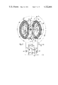
- FIG. 12 is a transverse cross section, perpendicular to the axis of rotation, of a two-pole external rotor motor having a cylindrical air gap;
- FIG. 13 is a developed view of the rotor of FIG. 12 with a schematic illustration of the stator coils superimposed;
- FIG. 14 is a view similar to FIG. 12, but illustrating an arrangement for a four-pole external rotor motor
- FIG. 15 is a view of transverse cross-section, perpendicular to the axis of rotation of another embodiment of a four pole external rotor motor.
- FIG. 16 is a developed view of the rotor of FIG. 14 or 15 with the stator coils being schematically shown.
- FIG. 17 is a view similar to FIG. 14 showing a different arrangement of coils in a four-pole external rotor motor.
- FIG. 18 is a views similar to FIG. 17 showing a different winding of coils in a four pole external rotor motor
- FIG. 19 is a developed view of the rotor and coil arrangement of FIG. 17 or 18,
- FIG. 20 is a highly schematic representation of a tacho generator winding formed as a lap winding for use with an axial air gap motor, for example of FIGS. 10 and 11,
- FIG. 21 is a schematic representation of a wave winding used as a tacho generator winding, for use in the axial air gap motor of FIG. 10 or 11, for example.
- FIG. 22 is a schematic representation of a permanent magnet pole surface for a planar air gap motor showing two strips of magnet surface
- FIG. 23 is a schematic representation of a developed permanent magnet surface for a cylindrical air gap motor showing two strips of magnet surface
- FIG. 24 is a schematic representation of a permanent magnet pole surface for a planar air gap motor showing three strips of magnet surface
- FIG. 25 is a schematic representation of a developed permanent magnet surface for a cylindrical air gap motor showing three strips of magnet surface
- FIG. 26 is a schematic representation of a developed permanent magnet surface for a cylindrical air gap motor showing three strips of magnet surface and magnet pole surface boundries at angles;
- FIG. 27 is a schematic representation of a developed permanent magnet surface for a cylindrical air gap motor showing two strips of magnet surface and magnet pole surface boundaries at angles.
- FIGS. 1 and 2 A motor shaft 1 has a hub 2 secured thereto by means of a press fit; the hub 2 preferably is in the shape of a belt pulley, made as a metal injection pressure casting.
- a soft iron or soft magnetic return disk 4 has a central opening 3 thereof secured to the hub 2, for example by being cast integrally therewith.
- a ring-shaped, axially magnetized ring magnet 5 is secured to disk 4, coaxially with respect to shaft 1.
- the hub 2 is formed with blind bore 7, the inner surface of which functions as a bearing surface 8 for a bearing tube 9 seated on shaft 1 with slight axial play. This construction is compact in an axial direction.
- the axial distance between the surface 8 and the surface 12 facing the axial air gap 11, and defined by the dimension arrow 10, is constructed with small tolerance.
- the bearing tube 9 is made of sintered metal and is tapered at its ends to formal journal or slide bearings 13, 14.
- the enlarged central portion 15 of the bearing tube 9 is secured, with a press fit, to a flanged disk 16 on which a stator plate 18 is secured at the side 17 facing away from the rotor assembly 6.
- the stator plate 18 is made of a plastic insulating material formed with cut-outs in which oppositely located coils 19, 20 are secured by an adhesive, for example epoxy, or the like.
- Two steel washer disks 23, 24 are located between the bearing surface 8 and the upper facing end surface 21 of the tube 9.
- the lower rotor disk 25 is formed as a soft magnetic return disk which is secured on shaft 1 with slight play and engages a locking disk 27 secured to shaft 1 in a groove 26 formed thereon.
- the magnetic return rotor disk 25 is pulled towards disk 4 by the axial attraction of the magnet 5, to securely retain disk 25 against the retaining ring or washer 27.
- the entire air gap is designated by the dimension arrow 29.
- the upper distance between rotor and stator is shown at 11, and the lower distance between rotor and stator at 11'.
- the end surfaces of the bearing tube 9 are unloaded with respect to the axial tension applied by the magnet 5 by the washer 27.
- a locking disk 32 is applied to the end shaft 1 to secure the return magnet rotor disk 25 against inadvertent removal from the shaft 1.
- FIG. 2 from which the invention will be particularly apparent, is highly schematic and the mechanical construction of the motor has been largely omitted since it is known.
- the rotor 5 of FIG. 2 is a two-pole rotor and can be subdivided into four characteristic zones:
- a zone 35 which, throughout its radial and axial extent is magnetized as a north pole, and having an angular extent of about 120°-el; in a two-pole construction, the mechanical degrees and electrical degrees are equal.
- first dipole zone 38 extending in the direction of rotation, as indicated by arrow 37, adjacent to the monopole zone 36, and having an angular extent of about 56°-el; and a second dipole zone 39, adjacent to dipole zone 38 and extending, likewise, over about 60°-el, in which the radial position of the poles of magnetization is reversed with respect to that of zone 38.
- the magnetization of the zones 38, 39 extends throughout the axial dimension of the magnet 5.
- the dipole zones 38, 39 are not uniformly magnetized over the entire radial width, as are the monopole zones 35, 36. Rather, the direction of the magnetic field changes along an imaginary radius vector.
- the outer ring segment 41 of dipole zone 38 is a south pole, the inner ring segment 42 a north pole; for the dipole zone 39, the outer segment 43 is a north pole and the inner ring segment 44 a south pole.
- the radial width and/or the magnetization of the respective ring segments is preferably so selected that the magnetic flux of the ring segments 41 and 42 is as equal as possible.
- the magnetic flux to be derived from ring segments 43, 44 should be equal. This equality of flux in the respective segments of the dipole zones is important when uniformity of torque is desired. Any one monopole zone and an adjacent dipole zone cover an arcuate extent of 180°-el.
- the volume of the magnets thereof should preferably be equal, which means that the radial extent of the inner one of the magnets may be slightly greater than the radial extent of the outer one.
- the stator coils 19, 20 of the coreless or air-core stator are approximately sector-shaped, as shown.
- the active portions extend radially outwardly; the junctions between the zones 35, 36, 38 and 39 are approximately parallel to the active portions of the coils, when the rotor is in a position in which the junctions between adjacent zones and the rotor coils are above each other.
- the south pole of the monopole zone 36 merges directly with the south pole of the outer ring segment 41 of the dipole zone 38.
- the north pole of the outer ring segment 43 of the dipole 39 merges directly with the north pole of the monopole zone 35.
- the outer circumference of the rotor magnet 5 thus has a north pole and a south pole, each, extending over about 180° each.
- a Hall generator 53 is located within the region of the outer portion of the rotor, secured to the stator plate 18. The Hall generator 53 is shown twice in FIG. 2, once in its actual location with respect to the rotor, and once, schematically, in the circuit to which the rotor is connected. The Hall generator, thus, is cyclically exposed to the magnetic field from the respective motor poles.
- One connection of the Hall generator 53 leads over a resistor 58 to a positive terminal or bus 59; the other power connection of the Hall generator 53 extends through resistor 60 to the negative or reference bus 61.
- the emitters of transistors 54, 55 are connected together over a common resistor 64 with positive bus 59.
- the collector of transistor 54 is connected over resistor 65 with the negative bus 61 and directly to the base of transistor 56, the emitter-collector path is connected between coil 9 and negative bus 61.
- the collector of transistor 55 is connected over resistor 66 with the bus 61 and further directly to the base of transistor 57, the emitter-collector path of which is connected between coil 20 and negative bus 61.
- the coils 19, 20 have their other winding ends connected to positive bus 59.
- the circuit of FIG. 2, as such, is known--see, for example, German Disclosure Document DE-OS No. 24 19 432, FIG. 1, where a similar circuit is used with a different type of motor, however. In motors of small power output it is not necessary to provide a two-stage amplifier circuit; for low-power application, the transistors 56, 57 may be omitted and coils 19, 20 can then be connected instead of resistors 65, 66.
- FIG. 3 shows another embodiment where the stator comprises a soft magnetic reflux-element 240.
- a rotor comprises a shaft 244, a refluxing magnet plate 246 and a permanent magnet section 248.
- the rotor is surrounded by a casing 250.
- a rotating magnetic field is provided by windings 252.
- the reflux soft magnetic plate 240 is disposed close to the windings 252.
- the shaft 244 is supported by a plate 254 to maintain its position in axial direction.
- a bushing 256 preferably from brass supports the shaft in a centered position.
- I 2 R losses and voltage drops due to wire resistances, friction losses and the like will be neglected. These losses can be compensated, for example, by operating the dynamo electric machine as a motor but supplying driving power thereto equal to losses.
- a voltage is induced in coil 20 having the negative amplitude u 1 (see FIG. 6).
- This position corresponds to the time instant t 0 (FIG. 6).
- the voltages induced in coils 19, 20 are shown in FIG. 6 with u 19 and u 20 .
- the negative voltage with amplitude u 1 can be readily explained by cutting of the magnetic field derived from the two monopoles 35, 36 by the active coil portions 47, 48 so that the voltages induced in the coil portions 47, 48 will add. Since the monopoles 35 and 36, just like coil 20, are approximately 120°-el long, this voltage is induced during an angle of rotation of about 120°-el. The voltages will not cut off in square wave form, but rather will drop off gradually, in rounded form, due to the transition between the poles over the relatively wide width of the coil portions.
- FIG. 4 illustrates the position of the rotor 5 upon further rotation.
- Coil 20 carries current, since Hall generator 53 is opposite a north pole, whereas coil 19 is de-energized, that is, will not carry current.
- the polarity of the voltage induced in coil 20 is reversed.
- This voltage u 2 will have a center or peak amplitude which has an absolute value u 2 which is only about half that of the absolute value of u 1 , which can readily be explained:
- the coil portions 48 cross the field lines of the monopole 35, that is, of a north pole.
- the coil portion 47 is influenced by the dipole 39, the opposite magnets 43, 44 of which induce in coil portion 47 voltages of equal magnitude but opposite polarity which, therefore, cancel.
- the amplitude u 2 is thus determined only by the field lines derived from monopole 35 and cutting the coil portion 48; thus, the amplitude is only half that of u 1 .
- the rotor position as shown in FIG. 3 occurs at an instant of time indicated in FIG. 5 at t 1 .
- the voltage waves show a large positive portion having two peaks 68 separated by a dip or valley 69. This non-uniformity between peaks and the dip therebetween can be largely eliminated or compensated by suitable choice of the shape of the coils, as will be described in detail below.
- the angle of rotation of the rotor during which a voltage with positive amplitude u 2 is induced in coil 20 extends over about 240°-el; the transition zone of the voltage shows a rounded curve. This can readily be explained based on physical laws since the time integral of the voltage induced in any one coil, upon rotation over 360°-el, must be zero, unless a d-c source is connected to the coil.
- the voltage u 20 induced in coil 20 is shown in broken lines in FIG. 6; the voltage induced in coil 19, u 19 , is shown in full lines. Due to the symmetry of the arrangement, the wave shapes will have the same appearance.
- the voltages u 19 and u 20 are idealized, that is, are shown for the case in which the rotor 5 is externally driven and the motor is not connected to a current source. In actual operation, and when connected as a motor, the voltage drops due to wire resistance at the respective current-carrying coils must be added to the voltages shown.
- FIG. 6 also shows the overlap of the positive portions of the voltages u 19 and u 20 .
- the condition is present that the motor is subject to a torque at any rotary position of the rotor upon energization of the coils, by energizing that one of the coils or a group of coils in which a positive voltage is being induced.
- each group of coils consists of only one coil element but, as can readily be seen, the same reasoning applies to multiple coils.
- the torque is given by the relationship
- u ind is the induced voltage which is induced in any one instant in a coil, in accordance with the above description; the i the then instantaneously flowing current through the coil; m the torque applied to the motor and ⁇ the angular speed of the rotor.
- the commutating instants are shown in FIG. 6 at t 3 , t 4 , t 5 , and they correspond to those rotor positions at which the Hall generator 53 is affected by a transition of flux between a south pole and a north pole.
- the Hall generator 53 is located on a line of symmetry 65 between the coils 19, 20, and spaced from the center of the shaft 1 by a radial distance 66.
- the distance 66 in a first example, is so selected that Hall generator 53 is affected only by the ring segments 41, 43 of the dipoles 38, 39 and by the monopoles, but not by the ring segments 42, 44 of the dipoles 38, 39.
- the ring segments 41, 43 of the dipoles 38, 39 need have only a sufficient width to suitably control the Hall generator 53 to conduction in the respective direction.
- graphs a and b show the two hall voltages u A and U B at the two outputs of the Hall generator 53 with respect to rotor position, that is, with respect to instantaneous rotor angle ⁇ .
- Graph c of FIG. 7 shows the currents i 19 and i 20 in the coils 19, 20.
- FIG. 7 also illustrates the effect of leakage or stray flux. Due to the greater stray flux of the magnetization device to magnetize the rotor, the flux density in the region of the ring segments 41, 43 will normally be somewhat smaller; this causes a drop in the Hall voltage when the Hall generator is exposed to the flux from those ring segments 41, 43, as illustrated by the step 67, in FIG. 7, graph a.
- FIG. 8 illustrates, schematically, the connection of Hall generator 53 and the voltages derived therefrom at the respective output terminals.
- FIG. 9 shows this relationship, in which the monopoles 35, 36 are joined to dipoles 38',39'.
- Dipole 38' has an outer segment 70 in form of a north pole, an inner segment 71 in form of a south pole.
- the dipole 39' similarly, has the outer segment 72 in form of a south pole, and the inner segment in form of a north pole.
- the radial distance 74 of Hall generator 53 from the center of shaft 1 is so selected that the Hall generator 53 will be within the range of rotation beneath the ring segments 71, 73, respectively, that is, within those segments of the dipole which have like polarity of the adjacent monopole.
- Hall sensors are preferred in accordance with the present State of the Art because they have two symmetrical outputs and thus permit direct control of current flow through the two coils 19, 20 in a symmetric arrangement. If the motor, for example, would be folded flat along a plane of symmetry 65, coils 19, 20 would fall above each other; these coils are, therefore, mirror images. Sensors such as field plates, magnetic diodes, magnetic field responsive resistors, and the like, may also be used, however, particularly in connection with suitable signal evaluation circuits which provide outputs suitable to control current flow through the respective coils 19, 20.
- Torque can be generated only at a location at which a current-carrying, magnetically active coil portion is in flux linkage relationship with a monopole of the rotor 5.
- torque is generated at the coil section 48; in FIG. 5 at coil section 47, and in FIG. 2 a transition occurs between coil section 50 to coil section 49.
- This change of the location of the generation of the torque places high requirements on the bearing with which rotor 5 is held.
- the bearing may have only very slight play since, otherwise bearing noise may result.
- the motor has more than two poles, and at least four poles should be used.
- the number of poles in the examples given herein, as well as in other examples, of course is related to the number of monopoles.
- FIGS. 10 and 11 illustrate a motor arrangement with four monopoles in an axial air gap motor.
- the forces which are applied by the stator to the rotor, at any instant of time, are symmetrical with respect to the rotor shaft 1 so that cyclically, rhythmically varying lateral forces applied to the bearings of shaft 1 are compensated and the requirements of accuracy and strength being placed on the bearing can be reduced.
- Similar parts and elements operating similarly to those previously described have been given the same reference numerals and will not be described again.
- FIGS. 10 and 11 The mechanical construction of the motor of FIGS. 10 and 11 is essentially similar to that of FIG. 1; the respective angles are shown in FIGS. 10 and 11.
- stator construction is also symmetrical with respect to a plane of symmetry 65.
- Hall generator 53 is located in that plane 65.
- Two coils are serially connected in the same direction of winding.
- the circuit can be identical to that of FIG. 2.
- the four coils 75, 76, 77, 78 have the same number of turns and are essentially trapeze shaped.
- the magnetically active portions of the coils have an approximate angular distance of about 120°-el from each other and extend essentially radially.
- transistor 56 When transistor 56 is conductive, current will flow from the positive bus 59 through coils 77, 75 and then transistor 56 to negative bus 61; upon conduction of transistor 57, current will flow from positive bus 59 through coils 76, 78 and through the conductive transistor 57 to negative bus 61.
- the currents are controlled by the Hall generator 53, commutation being effected after each rotation about 180°-el. In a four-pole motor, current is commutated four times for each revolution.
- the rotor 5' is shown in top representation in FIG. 10.
- a first monopole zone 80 forming a south pole extends from the 12 o'clock to the 2 o'clock position, followed by a dipole zone between the 2 and 3 o'clock position having an outer south and an inner north pole.
- the dipole zone 81 is joined to a second dipole zone 82 of reversed polarity between the 3 o'clock and 4 o'clock position, and then joined to another monopole 83 between the 4 o'clock and 6 o'clock position.
- the remaining sections of the monopoles 84, 87 and the dipoles 85, 86 are obvious from FIG. 9.
- the various angles are shown in FIG. 10.
- the flux generated in the dipole zones by the respective north and south poles thereof should be the same.
- the electrical angles of the motor in accordance with FIGS. 10 and 11 and of that in accordance with FIGS. 1 to 5 are the same.
- the operation will be identical, particularly the shape of the voltage induced in the motor when not carrying current, as illustrated in FIG. 6.
- the groups of the coils 75, 77 and 76, 78 are connected when the voltage with lower amplitude u 2 is induced therein; they are retained in connection for about 180°-el, that is, a quarter revolution.
- the spool group 76, 78 is connected after the prior connection of the spools 75, 77, and so on, in cyclical variation.
- the torque that is, the drive forces acting on the rotor 5'
- the torque is always generated at two radially oppositely located positions which, of course, change in the manner described in connection with FIGS. 1-5.
- Rhythmically changing lateral forces acting on the bearings are avoided, however, thus ensuring quieter running and less wear and tear mechanically.
- This feature is generally applicable to all motors having more than two poles, that is, monopoles, in which the principles of the present invention are used.
- the present invention is suitable for all types of motors, that is, whether of the axial air gap or cylindrical air gap type; motors having a cylindrical air gap can, additionally, be subdivided into motors having an external stator and an internal rotor, or an external rotor and an internal stator.
- the mechanical construction of cylindrical air gap motors is well known and the present invention is applicable to many types; it will be described, specifically, with respect to a motor illustrated, generally, in U.S. Pat. No. 3,703,221, assigned to the assignee of the present invention.
- the invention may be applied to two-pole, that is monopole motors, as well as motors having a multiple of two-pole pairs.
- a two-pole external rotor motor 90 has an external rotor 91 with an outer carrying ring 92 made of soft iron magnetic, that is, soft magnetic material.
- a ring magnet 93 is secured within the support element 92.
- the ring magnet is, for example, made of a flexible plastic material, typically a rubbery material, having magnetic particles located therein. Such structures are known as rubber magnets.
- the rubber magnet can be secured to the support 92 by an adhesive.
- the rubber magnet, and its magnetization, is shown in developed form in FIG. 13. Considering FIG.
- a monopole zone 94 forming a south pole is positioned adjacent a dipole zone 95 with an upper north pole and a lower south pole; adjacent thereto is a dipole zone 96, with reversed polarity, and followed by a monopole zone 97.
- the north pole of zone 95 is not visible since it is located behind the south pole, the view being from the bottom of FIG. 13 upwardly.
- Hall generator 53 is located in the plane of symmetry 65 of the stator 100.
- the rotor shaft 101 is journalled in suitable and well-known manner in the center of the stator 100.
- the stator itself is made of a laminated core 102 having an outer circular cylindrical circumference. Together with the rotor magnet 93 it defines an air gap 103 which has the same width at all circumferential positions, so that reluctance torques are avoided, that is, rotor 91 will not have any specific magnetically determined preferred position.
- the two stator coils 104, 105 are mirror images with respect to the plane of symmetry 65. They are indicated in chain-dotted lines in the development of FIG. 13. It is desirable to slightly offset Hall generator 53 counter the direction of rotation, as indicated by arrow 37, FIG. 12, from the plane of symmetry 65 in high-speed motors.
- the magnetically active coil sections of both coils include an angle of about 120°-el; the coils 104, 105 are adhered to the circular stator, since the stator winding is applied to a slotless or smooth stator core.
- Hall generator 53 is located within the circle of rotation of the rotor and so positioned that changeover the Hall generator occurs after each revolution extending over 180°-el, that is, in FIG. 13 at the lower portion of the path of rotation to be acted on by the monopoles and the like poled dipoles.
- the Hall generator is affected at each 180°-el, first by a south pole and during the next half revolution--with respect to electrical degrees--by a north pole.
- the south pole of monopole zone 94 merges directly with the south pole of the dipole zone 95; the north pole of the monopole zone 97 merges directly with the north pole of the dipole zone 96.
- FIG. 12 corresponds practically identically to FIG. 2 with the only difference that the straight magnetic path shown in the developed form of FIG. 13, is bent in ring shape, and the coils, similarly, then become sector-shaped.
- the two-pole motor of FIGS. 12 and 13 is subject to non-symmetrical bearing forces acting laterally, that is, radially on the bearing.
- FIGS. 14 and 16 show a four-pole motor having a cylindrical air gap 103.
- the stator core 102 of soft magnetic material, has four coils 110, 111, 112, 113 secured thereon, the magnetically active sections of which, as shown, have a distance from each other of about 240°-el.
- These four coils are shown in developed form in FIG. 16, together with the rotor magnet and its pattern of magnetization.
- the coils are connected in series, by serial connection of coil 110 with coil 112 and of coil 111 with coil 113.
- the connections to the transistors 56, 57 of the circuit of FIG. 2 are likewise shown.
- the position of Hall generator 53 with respect to the coils is clearly apparent from FIGS. 14 and 16, where the plane of symmetry 65 of the stator is also shown.
- the rotor 93 has four monopoles which, each, extend over 120°-el, and four dipoles, each extending over 60°-el.
- a monopole 116 next a dipole 117 with an upper south and a lower north pole, then a dipole 118 with an upper north and a lower south pole, a south-monopole 119, and north-monopole 120, another dipole 121 with an upper south and a lower north pole, a dipole 122 with reversed polarity, and finally a monopole 123.
- FIG. 14 is a developed figure, the monopole 123 would, in the closed cylinder, be placed adjacent the monopole 116.
- FIG. 14 is a developed figure
- the coil group having the coils 111, 113 have the lower voltage u 2 induced therein.
- the transistor 57 is controlled to be conductive. At that instant, thus, a drive torque is generated by the left active coil section 125 of coil 111 and by the left active coil section 126 of coil 113.
- FIG. 14 clearly shows that the coil sections 125, 126 are diametrically opposite each other, that is, rotor 91 has a drive torque applied thereto which is symmetrical with respect to shaft 101. The same relationship will occur in analogous manner with respect to the other coil sections when they take over the generation of the drive torque.
- the four coils 110 to 113 have a relatively high copper or wire resistance.
- the coil arrangement in accordance with FIG. 16 is preferred.
- the development of the arrangement of FIG. 16 is shown in FIG. 19.
- the magnetically inactive coil section, that is, the head ends of the loops, as is clearly seen, are substantially shorter and do not cross. This is particularly important when the motors are to have a short axial length.
- the four coils 130, 131, 132, 133 are symmetrically arranged and are so wound that their magnetically active section as shown, have a distance of 120°-el from each other.
- FIG. 19 is again shown with respect to the rotor magneti 93, which is identical to that shown in FIGS. 14 and 16.
- Hall generator 53 is also shown in FIG. 19, and its location relative to the coils, as well as the connection of coil 131 and coil 133 to form a first coil group, the current through which is controlled by transistor 56; and the connection of coil 132 and coil 130 to a second coil group, the current through which is controlled by transistor 57.
- the full voltage u 2 is induced in the coil groups 130, 132 since transistor 56 is blocked due to its control by Hall generator 53, whereas transistor 57 is controlled by Hall generator 53 to be conductive.
- the drive torque is generated by the right active coil section 135 of coil 131 and coil section 136 of coil 133. As clearly seen in FIG. 14, these coil sections are diametrically opposite each other, so that the generated torque again is symmetrical with respect to the shaft 101 and thus does not cause an unsymmetrical loading of the bearings for the rotor 91.
- Hall generator 53 is located in the region of the lower rotary path of rotor 91. It changes over it conductivity after each 180°-el rotation.
- the circuit is the same as that in FIG. 2; the connections of the Hall generator to the circuit must be so made, as noted above, that current will only flow in that group of coils in which the lower voltage +u 2 is induced, as explained in connection with FIG. 6.
- the angles h 2 , h 4 and h 5 shown in FIG. 14 determine the electrical phase relationships of the winding means.
- h 4 is the angle between a neighboring winding and a Hall element.
- h 2 is the angle between windings within 360° electrical and h 5 is the angle bezween windings corresponding to a 360° repeat angle.
- the angle h 4 can be from about 15° to 45° electrical.
- the angle h 2 can be from about 30° to 90° electrical and the angle h 5 can be from about 100° to 150° electrical and preferably from about 110° to 130° electrical.
- the embodiment shown in FIG. 14 has h 2 about equal 60° el; h 4 about equal 120° el.
- the angles g 1 , g 2 , g 3 and g 4 shown in FIG. 17 determine the electrical phase relationships of the winding means.
- g 1 is the angle of a pole provided by a winding
- g 2 is the angle between two neighboring windings
- g 3 is the angle between a central line of a winding and the connection line of the middle of the wound wires to the motor axis
- g 4 is the angle at the motor axis of the lines connecting to the magnetic sensor element and to the middle of the wound wires of a winding.
- g 1 can be from about 100° to 150° electrical and preferably from about 110° el to 130° el; g 2 can be from about 30° el to 90° el and g 4 can be from about 15° el to 45° el.
- the embodiment shown in FIG. 11 has g, about equal to 120° el, g 2 about equal to 60° el; g 3 about equal to 60° el and g 4 about equal to 30° el.
- FIG. 15 shows an embodiment similar to that of FIG. 14, however the windings are positioned on a slotted soft magnet case.
- FIG. 16 also corresponds to FIG. 15 and the angles h 2 , h 4 , h 5 of FIG. 15 correspond to those auf FIG. 14.
- the reference numerals of FIG. 16 also correspond to those of FIG. 15.
- FIG. 18 shows an embodiment similar to that of FIG. 17, however the windings are positioned on a slotted soft magnet core
- FIG. 19 also corresponds to FIG. 18 and the angles g 1 , g 2 , g 3 , g 4 of FIG. 18 correspond to those of FIG. 17.
- the reference numerals shown in FIG. 18 also correspond to those of FIG. 17.
- the leakage or stray field from the motor in actual practice, is particularly effective on the outer winding portions of the coils with which the rotor interacts and causes a deformation of the theoretical flat curve, thus inducing the pips 68, shown in FIG. 6.
- This deformation of the induced voltage which, when the motor current remains uniform, causes a corresponding variation of the torque which is particularly annoying if the motor is to be used for direct drive of audio equipment, for example phonograph turntables or the like which require output torque of high uniformity.
- the deviation from the idealized coil form is shown in FIG. 2 for the right coil 20 by superimposing thereon the actual, desirable coil form shown in chain-dotted lines 150, 151.
- the resulting coil as shown, is approximately a pentagon. This shape is derived by decreasing the coil surface in the region of that portion of the rotary path of the rotor 5 which controls the Hall generator 53, that is, in the embodiment of FIG. 2, the outer region of the rotor.
- the corners 152, 153 of the coils above or close to that portion of the rotary path of the rotor are cut or chamfered. Identical considerations of course apply for coil 19 of FIG. 2 where the superimposed showing of the actual desirable coil form has been omitted for clarity.
- the upper envelope of the induced voltage thus has a much lesser degree of waviness or ripple by inclining or relieving the corners 152, 153 of the coil, and the overall torque derived from the motor will become substantially more uniform.
- the extent of chamfering or relieving the corners 152, 153 depends on the overall shape of the coil, the magnetization of the rotor, its size and shape, and the quality of magnetization, and the stray field thereof. It is best determined by experiments starting with a coil shape which is approximately that indicated by the chain-dotted lines 150, 151 in FIG. 2, for example, or by measuring the extent of the stray field from a particular rotor construction.
- FIG. 9 illustrates the type of coil which is suitable for a motor in which the Hall generator 53 is located at an inner circumferential path of the rotor.
- a suitable coil form is shown in broken lines at 140 (FIG. 9).
- the segments 71, 73 of the dipole zones 38', 39' are located radially inwardly.
- the magnetically active coil sections do not extend radially outwardly through an essential portion of their length, but rather extend under an angle 155 of, for example, about 30° with respect to an intersecting radius vector 156.
- the radial extent of the coils themselves has been reduced to about 50 to 60% of the width of the magnets. None of these angles, nor the reduction in length of the magnetically active coil sections is critical. The exact matching of the shape of the coils to a specific rotor for minimum ripple can be easily determined experimentally.
- a coil shape 141 for use with a rotor magnet 5' which has been found suitable in actual practice is shown in FIG. 11.
- the Hall generator 53 is located at a radially external circumferential path of the magnet which is shown in broken lines 142, 143 with respect to the upper coil segments.
- the open window 144 of the coil corresponds to the preferred relation B S :B M ⁇ 0.9.
- the coil window is approximately in the shape of a pentagon which is symmetrical with respect to a 90° line 145, and which has a tip 146 facing outwardly, that is, towards the circumferential path which also controls the Hall generator 53.
- the outer shape of the coil 141 is almost circular. This is due to the winding of the coil and has been found suitable in actual practice.
- broken-lines 160, 161 show the actual coil shape--in developed form--as distinguished from the ideal coil shape shown in chain-dotted lines and used in connection with the theoretical explanation of the invention. Again, the coils will have an approximate pentagon shape, the tip of which is directed towards the side of the magnet which controls the Hall generator 53. The rounding or relieving of the corners extends, in accordance with operating experience, usually only to the first quarter of the width of the magnet, as shown in FIGS. 11 and 13. The angle of inclination is a function of the respective width of the poles. Motors having many poles will require a greater extent or angle of inclination than motors with fewer poles.
- the coils should also have the shape indicated in broken lines 160, 161 in FIG. 13, with the tip of the five-corner polygon being directed towards the Hall generator 53 which controls the lower rotary portion of the rotor.
- the relieving of the corners has not been shown in FIGS. 16 and 19 for clarity in the drawings. If the Hall generator 53 would be controlled from the upper section, then the tip of the pentagon would have to be directed upwardly.
- the particular magnetization of the rotor permits use of the motor as a tachogenerator, or to use the motor in combination with a speed controller.
- Speed control is independent of the magnitude of the magnetic flux density of the rotor magnet if frequency of induced voltage is used as a measure of actual speed rather than amplitude.
- the dynamic characteristic of a controller which uses frequency as a measure for instantaneous speed is that much better, the higher the frequency.
- the voltage induced in the main winding of a brushless d-c motor in operation upon rotation of the rotor usually has a comparatively low frequency. In the present motor the frequency is: ##EQU9## wherein the speed n is measured in rpm, and p is the number of pole pairs of the monopoles.
- This frequency is often not sufficient for effective speed control, particularly if the speed n is small, which is the case if the motor is to be used as a direct drive motor for a phonograph turntable, record player, or the like, which operates at 331/3 rpm.
- An output signal is derived from a winding which, when combined with the motor, is an auxiliary winding and located either only in that portion of the air gap of the rotor magnet in which the dipole regions have the reverse polarity as the adjacent monopoles or only in that region of the air gap in which the segments of the dipole width is the same as that of the adjacent monopole.
- the additional winding can be wound, for example, as a lap winding with three p single coils, in which p is the number of pole pairs of the monopoles.
- FIG. 20 for use with a rotor 5' as illustrated in FIG. 10.
- the specific construction of the rotor has been shown only schematically to clarify the drawing, and reference is made to the discussion in connection with FIG. 10 for a detailed description.
- the six separate coils 165 have a width of 30°-mechanical and a distance of 30°-mechanical and are placed above the inner rotary portion of rotor 5'.
- the coils are serially connected.
- the external connections are shown at 166.
- a speed control circuit can be connected to terminals 166, which analyzes the frequency of the induced voltage forming the output signal at terminals 166.
- the form of the tacho generator winding with single coils can be used, equally, in motors having a cylindrical air gap.
- a wave winding is suitable which can readily be constructed in form of a meander or undulating winding 167, applied as a printed circuit to a flat plate, and as shown in FIG. 21.
- the undulating winding 167 preferably is secured to a thin insulating foil as a printed circuit, for example applied in a screen printing process and then etched.
- the inner terminals 168 and 169 are part of the printed circuit. Due to the relatively small number of windings of the printed circuit, it is desirable to amplify the resulting output signal before further processing the signal.
- the undulating winding of FIG. 21 is so constructed that it is affected only by the inner portion of the rotor 5'. Alternatively, it could be so constructed that it is affected only by the outer portion thereof.
- Constructing the winding 167 as a printed circuit has the further advantage that several foils of such undulating windings 167 can be stacked above each other.
- n foils it is possible to offset the respective windings of the respective foils by 180°-el/n.
- the degrees are referred to the pole pitch of the meander or undulating winding.
- two foils for example which are then offset 90°-el with respect to each other, it is necessary to offset the foil by a mechanical actual angle of 15° with respect to each other.
- Two 90° offset output voltages are then obtained from the two foils. Upon subsequent full-wave rectification of these voltages, the frequency of the output is doubled once more.
- Coils 165 or the undulating loops 167 within the region of the monopoles of the rotor 5' have no voltage induced therein as long as there is no change in magnetic flux derived from the monopoles. This is the case in two p coils, or undulating loops, respectively; in FIG. 20 or 21, in four coils or undulating loops.
- the other p coils have a voltage induced therein.
- voltages are induced in two coils 165 in which the dipole segments change from polarity N to the dipole segments of the polarity S. This change occurs sequentially during one revolution in all three p coils, that is, three p-times for each revolution.
- the motor having four monopoles thus will have twelve changes although the magnetic flux in the main winding changes only four times for each revolution.
- a voltage thus is induced in the undulating winding 167 of FIG. 21 or in the three p serially connected separate coils 165 of FIG. 20 which has a small amplitude with respect to that of the main coils, but which has a frequency which is three times that of the voltage induced in the main coil. Since the voltage induced in the measuring windings 165, 167 has a higher frequency, it provides a desirable output signal for a speed control system in which the frequency of rotary induced voltage is used as a control parameter for revolution of the motor.
- the auxiliary or tacho winding can be used with any sensor; it is particularly suitable for use when the sensor is a Hall generator, but the tacho winding itself is independent of the commutation sensing device.
- the permanent magnet rotor comprises a first outer strip and a second inner strip of permanent magnet material.
- the width of the outer strip is c 1 and the width of the inner strip is c 2 .
- the outer strip 181 comprises one magnetic south pole and one magnetic north pole surface.
- the inner strip 183 shows two permanent magnet pole surfaces of different polarity for each pole surface on the outer strip, a larger one 183 having the same polarity as the one coordinated of the inner strip and a smaller one 187 having opposite polarity to the pole surface coordinated on the outer strip.
- each pole surface on the second inner strip is neighbored on the inner strip on each side a pole surface of opposite polarity of in general different extension and with the one having the larger extension being coordinated to a permanent magnet pole surface of the same polarity on the outer strip.
- annular space 185 without magnetic material.
- annular space is kept as narrow as possible since it does not provide for electromagnetic interaction with the winding means.
- FIG. 23 shows a corresponding construction for as an unwound surface for a cylindrical air gap motor or for a linear motor.
- the designations correspond to those of FIG. 22.
- the extension a corresponds to 360° electrical and the extension a 1 corresponds to the extension of the permanent magnet pole on the second strip having the same polarity as the coordinated pole on the first strip.
- FIG. 24 is shown an embodiment of the present invention employing three magnetic strips, to wit an inner strip 203 of extension b 3 -b 1 , an outer strip 201 of extension b 2 -b 4 and a middle strip 205 of extension b 4 -b 3 .
- the middle strip corresponds to the first strip as designated above and the inner and outer strips correspond to the second strip as mentioned above.
- the winding means are not shown and they are similar to those shown in FIG. 2,4 to 5 or FIG. 13.
- the middle strip is shown with two permanent magnet pole surfaces each extending over 180° electrical in FIGS. 24 and 25 and over 180° mechanical in FIG. 24. A magnetic sensing element would be disposed near the middle strip. When the width of either the outer or the inner permanent magnet surface goes to zero, then the embodiment with the two strips is present.
- FIGS. 26 and 27 show two embodiments wherein not all boundaries between the permanent magnet pole surfaces are either in the direction of motion or normal to it, but there are also shown pole surface boundaries at angles. This is not limited to a cylindrical air gap or a linear motor, but holds also for a planar air gap motor.
- FIG. 26 corresponds in some respects to FIGS. 24 and 25 and FIG. 27 as a special case of FIG. 26 corresponds to FIGS. 12 and 13 in some respect.
- These permanent magnet pole surfaces are employed in conjunction with and in a like fashion as is described above for other embodiments of the motor of the present invention.
- a 1 is the extension or angle(electrical) corresponding to the length where the permanent magnet surface has the same polarity over the full width for a pole pitch.
- the middle strip 225 or the strip 235 corresponding to the first strip is shown as having a width b 4 -b 3
- the upper strip 221 or 231 is shown having a width of b 2 -b 4
- the lower strip 223 is shown as having a width of b 3 -b 1 .
- upper and lower strip correspond closely to the second strip described above.
- the motor can be used not only to provide an essentially uniform output torque, but also output torque which varies in a roughly stepped pattern. By non-uniformly magnetizing the dipole zones, the output torque will fluctuate. It is possible to generate a torque with pronounced stepped wave shape by unequally magnetizing the magnetic areas. Motors with such torque shape are used for some applications in which the output torque should fluctuate or vibrate.
- the motor is to have particularly uniform output torque, then it may be desirable to increase the current through the motor coils at the instant of commutation, that is, at time periods t 6 , t 7 , as shown in FIG. 7, graph c, particularly when combined with the arrangements to make the output torque uniform.
- Supplying the motor with constant current, use of dipole-magnetic regions of uniform, equal flux, and coils with chamfered, relieved corners at the side facing the Hall generator provides highly uniform drive torque.
- the coil form 140 of FIG. 9, or 141 of FIG. 11 is particularly preferred.
- a four-pole axial air gap motor with a coil shape as shown at 141 in FIG. 11 provided measured output torque variations of ⁇ 10%.
- Hall generators as galvano magnetic sensors is preferred; these generators are inexpensive and small and permit elimination of additional or accessory devices to control commutation, such as separate control magnets, contacts, induction coils, and the like.
- the magnetized region within the circumferential path in the dipole zone need only be as wide as required for proper control of such a galvano magnetic sensor.
- the preferred form of the invention uses motors which have four or more poles to reduce non-symmetrical loading on the bearings.
- the coils when used with axial air gap motors, are preferably coreless or air-core coils; motors with cylindrical air gap, whether for use as an internal or external rotor motor, are preferably applied to a slotless stator, in order to entirely or in any event essentially avoid reluctance torques which cause disturbances and interferences.
Landscapes
- Engineering & Computer Science (AREA)
- Power Engineering (AREA)
- Brushless Motors (AREA)
- Permanent Magnet Type Synchronous Machine (AREA)
- Control Of Motors That Do Not Use Commutators (AREA)
Abstract
Description
(1-d)a(c.sub.1 +c.sub.2)≦6(a-2a.sub.1)c.sub.2 ≦(1+d)a(c.sub.1 +c.sub.2)
m·ω=u.sub.ind ·i (1)
Claims (83)
(1-d)·a(c.sub.1 +c.sub.2)≦6(a-2a.sub.1)c.sub.2 ≦(1+d)·a(c.sub.1 +c.sub.2)
Applications Claiming Priority (2)
| Application Number | Priority Date | Filing Date | Title |
|---|---|---|---|
| DE2730142A DE2730142C2 (en) | 1977-07-04 | 1977-07-04 | Brushless DC motor of the two-strand design |
| DE2730142 | 1977-07-04 |
Related Parent Applications (1)
| Application Number | Title | Priority Date | Filing Date |
|---|---|---|---|
| US06/212,502 Continuation-In-Part US4371817A (en) | 1977-07-04 | 1980-12-03 | Brushless, permanent magnet d-c pulse current controlled, essentially uniform torque dynamo electric machine, particularly motor |
Publications (1)
| Publication Number | Publication Date |
|---|---|
| US4322666A true US4322666A (en) | 1982-03-30 |
Family
ID=6013121
Family Applications (3)
| Application Number | Title | Priority Date | Filing Date |
|---|---|---|---|
| US05/919,702 Expired - Lifetime US4211963A (en) | 1977-07-04 | 1978-06-27 | Brushless, permanent magnet d-c pulse current controlled, essentially uniform torque dynamo electric machine, particularly motor |
| US06/212,502 Expired - Lifetime US4371817A (en) | 1977-07-04 | 1980-12-03 | Brushless, permanent magnet d-c pulse current controlled, essentially uniform torque dynamo electric machine, particularly motor |
| US06/250,224 Expired - Lifetime US4322666A (en) | 1977-07-04 | 1981-04-02 | Brushless, permanent magnet d-c pulse current controlled, essentially uniform torque dynamo electric machine particularly motor |
Family Applications Before (2)
| Application Number | Title | Priority Date | Filing Date |
|---|---|---|---|
| US05/919,702 Expired - Lifetime US4211963A (en) | 1977-07-04 | 1978-06-27 | Brushless, permanent magnet d-c pulse current controlled, essentially uniform torque dynamo electric machine, particularly motor |
| US06/212,502 Expired - Lifetime US4371817A (en) | 1977-07-04 | 1980-12-03 | Brushless, permanent magnet d-c pulse current controlled, essentially uniform torque dynamo electric machine, particularly motor |
Country Status (7)
| Country | Link |
|---|---|
| US (3) | US4211963A (en) |
| JP (1) | JPS5441406A (en) |
| CH (1) | CH642496A5 (en) |
| DE (1) | DE2730142C2 (en) |
| FR (1) | FR2397089A1 (en) |
| GB (1) | GB2000646B (en) |
| HK (1) | HK5885A (en) |
Cited By (32)
| Publication number | Priority date | Publication date | Assignee | Title |
|---|---|---|---|---|
| US4494028A (en) * | 1982-09-30 | 1985-01-15 | Rotron Incorporated | Integral coaxial commutation and rotor magnets and apparatus and method for making same |
| US4563622A (en) * | 1984-07-12 | 1986-01-07 | Rotron Incorporated | Simple brushless DC fan motor |
| US4564793A (en) * | 1983-09-28 | 1986-01-14 | Rotron, Incorporated | Brushless DC motor with improved starting |
| US4707645A (en) * | 1986-07-25 | 1987-11-17 | Shicoh Engineering Co., Ltd. | Single-phase brushless motor |
| US4779069A (en) * | 1982-09-30 | 1988-10-18 | Comair Rotron, Inc. | Apparatus and method for making integral coaxial communication and rotor magnets |
| US5293093A (en) * | 1991-11-25 | 1994-03-08 | Mpc Products Corporation | Limited large angle rotary dynamoelectric machine |
| US5654598A (en) * | 1995-12-14 | 1997-08-05 | Siemens Electric Limited | Brushless motor with inside mounted single bearing |
| US5675206A (en) * | 1995-12-18 | 1997-10-07 | Siemens Electric Limited | Slim-line brushless motor |
| US5823165A (en) * | 1996-02-23 | 1998-10-20 | Unisia Jecs Corporation | Valve actuator arrangement for internal combustion engine |
| US5834873A (en) * | 1983-09-05 | 1998-11-10 | Papst Licensing Gmbh | Brushless three-phase dc motor |
| US5844338A (en) * | 1995-12-18 | 1998-12-01 | Siemens Electric Limited | Slim-line brushless motor with inside mounted single bearing |
| WO2003085805A3 (en) * | 2002-04-08 | 2004-03-18 | Geok Hwee Chng | Rotating electric machine |
| US20050116675A1 (en) * | 2003-12-01 | 2005-06-02 | Dooley Kevin A. | Sensorless control in a permanent magnet machine |
| US20080024044A1 (en) * | 2006-07-26 | 2008-01-31 | Dynamic Energy Corporation Inc. | Electric Motor |
| US20080218007A1 (en) * | 2004-12-17 | 2008-09-11 | Hitachi Metals, Ltd. | Rotor for Motor and Method for Producing the Same |
| US20090278481A1 (en) * | 2008-05-06 | 2009-11-12 | Palmer Denis L | Apparatus and system for efficiently controlling a hub motor |
| US20100041504A1 (en) * | 2008-08-13 | 2010-02-18 | Denis Palmer | Apparatus, System, and Method for a Variable Ratio Transmission |
| US20100084938A1 (en) * | 2008-08-15 | 2010-04-08 | Millennial Research Corporation | Regenerative motor and coil |
| US20110062901A1 (en) * | 2007-08-16 | 2011-03-17 | Dorma Gmbh + Co. Kg | Arrangement of Stator Modules in a Linear Motor |
| US20110181131A1 (en) * | 2010-01-25 | 2011-07-28 | Pu yong-hua | Flat vibrating motor |
| US20110221295A1 (en) * | 2010-03-09 | 2011-09-15 | Zhongshan Broad-Ocean Motor Co., Ltd. | Permanent magnet rotor and motor using the same |
| US20110234180A1 (en) * | 2010-03-29 | 2011-09-29 | Rolls-Royce Plc | Electrical machine safety system |
| US20110291532A1 (en) * | 2010-05-26 | 2011-12-01 | Seiko Epson Corporation | Coreless electromechanical device |
| KR101098150B1 (en) | 2007-07-10 | 2011-12-26 | 밀레니얼 리서치 코오포레이숀 | Electric motor |
| US20140167572A1 (en) * | 2012-12-14 | 2014-06-19 | Lg Innotek Co., Ltd. | Motor and sensing magnet of the same |
| US9139767B2 (en) | 2008-12-30 | 2015-09-22 | Nanosys, Inc. | Methods for encapsulating nanocrystals and resulting compositions |
| US9199842B2 (en) | 2008-12-30 | 2015-12-01 | Nanosys, Inc. | Quantum dot films, lighting devices, and lighting methods |
| US20150381018A1 (en) * | 2013-02-04 | 2015-12-31 | Halla Visteon Climate Control Corporation | Brushless dc motor with reduced emissions |
| US10038349B2 (en) | 2008-08-15 | 2018-07-31 | Millennial Research Corporation | Multi-phase modular coil element for electric motor and generator |
| US10214686B2 (en) | 2008-12-30 | 2019-02-26 | Nanosys, Inc. | Methods for encapsulating nanocrystals and resulting compositions |
| US20210336513A1 (en) * | 2018-10-26 | 2021-10-28 | Borgwarner Inc. | Rotating machine and method of using the same |
| US11198270B2 (en) | 2008-12-30 | 2021-12-14 | Nanosys, Inc. | Quantum dot films, lighting devices, and lighting methods |
Families Citing this family (60)
| Publication number | Priority date | Publication date | Assignee | Title |
|---|---|---|---|---|
| DE2730142C2 (en) * | 1977-07-04 | 1988-01-21 | Papst-Motoren GmbH & Co KG, 7742 St Georgen | Brushless DC motor of the two-strand design |
| DE2850478C3 (en) * | 1978-11-21 | 1981-10-15 | Siemens AG, 1000 Berlin und 8000 München | Electronic motor with a multi-pole external rotor |
| DE2901676A1 (en) * | 1979-01-17 | 1980-08-14 | Papst Motoren Kg | COLLECTORLESS DC MOTOR |
| DE2933437A1 (en) * | 1979-08-17 | 1981-03-26 | Siegas Metallwarenfabrik Wilhelm Loh Gmbh & Co Kg, 5900 Siegen | ENCLOSED MOTOR COMPRESSOR FOR PARTICULAR REFRIGERATORS |
| JPS5656162A (en) * | 1979-10-09 | 1981-05-18 | Matsushita Electric Ind Co Ltd | Dc rotary motor |
| JPS56123790A (en) * | 1980-02-29 | 1981-09-29 | Sony Corp | Driving circuit for two phase |
| US5361010A (en) * | 1980-07-09 | 1994-11-01 | Papst Licensing Gmbh | Tachogenerator for speed control of electric motors |
| US4517480A (en) * | 1980-07-09 | 1985-05-14 | Papst Motoren Gmbh & Co, Kg | Tachogenerator for speed control of electric motors |
| JPS5722366A (en) * | 1980-07-15 | 1982-02-05 | Tokyo Parts Kogyo Kk | Commutatorless motor |
| JPH036149Y2 (en) * | 1981-01-13 | 1991-02-15 | ||
| JPS57132753A (en) * | 1981-02-06 | 1982-08-17 | Japan Servo Co Ltd | Dc brushless motor |
| US4508998A (en) * | 1981-02-09 | 1985-04-02 | David H. Rush | Brushless disc-type DC motor or generator |
| JPS57186976A (en) * | 1981-05-08 | 1982-11-17 | Nippon Densan Kk | Brushless motor |
| DE3120559A1 (en) * | 1981-05-23 | 1982-12-09 | Robert Bosch Gmbh, 7000 Stuttgart | REACTIVE SERVO DRIVE |
| JPS5895184U (en) * | 1981-12-18 | 1983-06-28 | アルプス電気株式会社 | DC brushless motor |
| US4529934A (en) * | 1982-01-18 | 1985-07-16 | Papst-Motoren Gmbh & Co. Kg | Apparatus for detecting a predetermined angular position on rotating devices |
| CH660264A5 (en) * | 1982-05-27 | 1987-03-31 | Papst Motoren Gmbh & Co Kg | COLLECTORLESS DC MOTOR. |
| ATE26634T1 (en) * | 1982-12-10 | 1987-05-15 | Micronel Ag | FAN WITH ELECTRONICALLY COMMUTATED DC MOTOR. |
| JPH0622394B2 (en) * | 1983-01-14 | 1994-03-23 | ソニー株式会社 | 3-phase brushless motor |
| JPS59183180U (en) * | 1983-05-23 | 1984-12-06 | 沖電気工業株式会社 | Flat type DC brushless motor |
| US4553075A (en) * | 1983-08-04 | 1985-11-12 | Rotron Incorporated | Simple brushless DC fan motor with reversing field |
| DE3434965A1 (en) * | 1983-09-22 | 1985-04-04 | Papst-Motoren GmbH & Co KG, 7742 St Georgen | ENCLOSED SMALL ENGINE |
| US4556828A (en) * | 1983-11-02 | 1985-12-03 | Sanders Associates, Inc. | Electric motor adapted to permit translational motion between field and armature |
| DE3526166C2 (en) * | 1984-07-23 | 1996-05-02 | Asahi Chemical Ind | Brushless electric motor and method of manufacturing a coil unit therefor |
| CH660542A5 (en) * | 1984-08-31 | 1987-04-30 | Asgalium Sa | ELECTRIC MOTOR. |
| DE3439665A1 (en) * | 1984-10-30 | 1986-05-07 | Ebm Elektrobau Mulfingen Gmbh & Co, 7119 Mulfingen | COLLECTORLESS DC MOTOR |
| JPH0135556Y2 (en) * | 1984-11-05 | 1989-10-30 | ||
| US4618806A (en) * | 1985-02-11 | 1986-10-21 | Rotron, Inc. | Ironless, brushless DC motor with wave-winding |
| JPS61247262A (en) * | 1985-04-25 | 1986-11-04 | Sony Corp | Detector for rotational position |
| JPS62201048A (en) * | 1986-02-27 | 1987-09-04 | Sony Corp | Two-phase brushless motor |
| NL8601869A (en) * | 1986-07-17 | 1988-02-16 | Philips Nv | ELECTRIC MACHINE. |
| DE3713304A1 (en) * | 1987-04-18 | 1988-11-03 | Heldt & Rossi Servoelektronik | DEVICE FOR DETECTING TURNING ANGLE POSITION IN ROTARY DRIVES |
| US4751415A (en) * | 1987-04-28 | 1988-06-14 | Matsushita Electric Industrial Co., Ltd. | Brushless DC motor with means for compensating ripple torque |
| US4883999A (en) * | 1988-08-15 | 1989-11-28 | Pacific Scientific Company | Polyphase electronically commutated reluctance motor |
| US4950960A (en) * | 1989-03-27 | 1990-08-21 | General Electric Company | Electronically commutated motor having an increased flat top width in its back EMF waveform, a rotatable assembly therefor, and methods of their operation |
| JPH0756616Y2 (en) * | 1990-08-07 | 1995-12-25 | 株式会社ゼクセル | Magnetization structure of motor rotor magnet |
| JPH04109896A (en) * | 1990-08-28 | 1992-04-10 | Secoh Giken Inc | Torque ripple eliminator of reluctance-type motor |
| US5512871A (en) * | 1990-12-17 | 1996-04-30 | Moving Magnet Technologies S.A. | Rotatable single-phase electromagnetic actuator |
| FR2675322A1 (en) * | 1991-04-11 | 1992-10-16 | Ebauchesfabrik Eta Ag | ELECTROMAGNETIC MICROMOTOR WITH AXIAL FLUX. |
| US5550414A (en) * | 1992-12-10 | 1996-08-27 | Kabushiki Kaisha Sankyo Seiki Seisakusho | Motor |
| US5631508A (en) * | 1993-07-27 | 1997-05-20 | Mitsumi Electric Co., Ltd. | Cost-saving, small-sized motor with improved stability over wide speed range |
| US6366037B1 (en) * | 1997-08-18 | 2002-04-02 | Rolf Strothmann | Separately excited electric machine |
| US6437529B1 (en) | 1998-05-04 | 2002-08-20 | Comair Rotron, Inc. | Multi-stator motor with independent stator circuits |
| KR20000009230A (en) * | 1998-07-22 | 2000-02-15 | 윤종용 | Brushless dc motor |
| US6046518A (en) * | 1999-01-21 | 2000-04-04 | Williams; Malcolm R. | Axial gap electrical machine |
| US6005320A (en) * | 1999-06-22 | 1999-12-21 | Amotron Co., Ltd. | Two-phase brushless direct-current motor having single hall effect device |
| US6450772B1 (en) * | 1999-10-18 | 2002-09-17 | Sarcos, Lc | Compact molecular drag vacuum pump |
| US6407521B1 (en) * | 2001-09-17 | 2002-06-18 | Ford Global Technologies, Inc. | Adaptive demagnetization compensation for a motor in an electric or partially electric motor vehicle |
| US6762527B1 (en) * | 2003-06-19 | 2004-07-13 | Yea Huey Horng | DC brushless motor |
| JP2005333714A (en) * | 2004-05-19 | 2005-12-02 | Niitekku:Kk | Simple structure dc motor and its constitution method |
| US20100303652A1 (en) * | 2007-05-10 | 2010-12-02 | Industrial Technology Research Institute | Miniature heat-dissipating fan device |
| US20090021100A1 (en) * | 2007-07-19 | 2009-01-22 | Sheng-Chung Lee | Stator Structure of External-rotor Motor |
| TW200913442A (en) * | 2007-09-05 | 2009-03-16 | Chuan-Sheng Chen | Coilless motor |
| US20110309315A1 (en) * | 2008-12-22 | 2011-12-22 | Williams Kevin R | Two speed direct drive drawworks |
| TWI384748B (en) * | 2009-04-03 | 2013-02-01 | Anpec Electronics Corp | Driving method and related driving device for a motor |
| US8745990B2 (en) * | 2009-07-27 | 2014-06-10 | Rolls-Royce Corporation | Gas turbine engine with integrated electric starter/generator |
| US8872395B2 (en) * | 2009-11-04 | 2014-10-28 | Fraen Mechatronics, Llc | Rotary single-phase electromagnetic actuator |
| DE202009015515U1 (en) | 2009-11-17 | 2011-04-07 | Novopress Gmbh Pressen Und Presswerkzeuge & Co. Kommanditgesellschaft | Hand-held pressing device |
| CA3031369A1 (en) * | 2016-07-20 | 2018-01-25 | Dumitru Bojiuc | Variable magnetic monopole field electro-magnet and inductor |
| KR102380348B1 (en) * | 2017-03-24 | 2022-03-31 | 삼성전자주식회사 | Wireless power transmitter and method for transmitting wireless power according to an aspect of a cradle in a wireless power transmitter |
Citations (7)
| Publication number | Priority date | Publication date | Assignee | Title |
|---|---|---|---|---|
| US3299335A (en) * | 1963-03-12 | 1967-01-17 | Philips Corp | Self-starting direct-current motors having no commutator |
| US3873897A (en) * | 1972-05-25 | 1975-03-25 | Papst Motoren Kg | Collector-less D-C motor |
| US3986086A (en) * | 1972-05-25 | 1976-10-12 | Papst-Motoren Kg | Control circuit for brushless D-C motor |
| US4030005A (en) * | 1974-04-23 | 1977-06-14 | Papst-Motoren Kg | Brushless d.c. motor having rotor position-dependent control means |
| US4115715A (en) * | 1974-04-08 | 1978-09-19 | Papst-Motoren Kg | Brushless d. c. motor |
| US4211963A (en) * | 1977-07-04 | 1980-07-08 | Papst-Motoren Kg | Brushless, permanent magnet d-c pulse current controlled, essentially uniform torque dynamo electric machine, particularly motor |
| US4217508A (en) * | 1977-04-08 | 1980-08-12 | Sony Corporation | DC motor |
Family Cites Families (19)
| Publication number | Priority date | Publication date | Assignee | Title |
|---|---|---|---|---|
| DE1613380U (en) | 1949-12-27 | 1950-09-21 | H & H Bruegmann Jun | SCREW SOCKET. |
| US2980839A (en) * | 1959-02-12 | 1961-04-18 | Haeussermann Walter | Electric motor |
| US3132296A (en) | 1960-02-01 | 1964-05-05 | Carrier Corp | Dynamoelectric machine excitation system |
| FR1388848A (en) * | 1963-12-23 | 1965-02-12 | Csf | DC motor using the hall effect |
| US3354329A (en) * | 1964-01-14 | 1967-11-21 | Reich Robert Walter | Magnet arrangement for electric and electronic clocks |
| US3383574A (en) * | 1964-06-30 | 1968-05-14 | Gen Electric | Brushless direct current motor and torquer |
| DE1925332B2 (en) | 1968-05-21 | 1974-07-18 | Matsushita Electric Industrial Co. Ltd., Kadoma, Osaka (Japan) | Commutatorless DC motor with a permanent magnet rotor |
| DE1964889C2 (en) * | 1969-12-24 | 1987-08-20 | Papst-Motoren GmbH & Co KG, 7742 St Georgen | Arrangement for returning escaping lubricant in an electric motor |
| DE2225442C3 (en) * | 1972-05-25 | 1984-06-28 | Papst-Motoren GmbH & Co KG, 7742 St Georgen | Brushless DC motor |
| JPS509098A (en) * | 1973-05-31 | 1975-01-30 | ||
| LU68101A1 (en) * | 1973-07-26 | 1973-11-22 | ||
| DE7328327U (en) * | 1973-08-02 | 1977-08-11 | Papst-Motoren Kg, 7742 St Georgen | COLLECTORLESS DC MOTOR |
| JPS5520146Y2 (en) * | 1974-01-17 | 1980-05-14 | ||
| JPS51129605A (en) * | 1975-04-04 | 1976-11-11 | Tasuku Eng Kk | No-commutator d-c motor |
| JPS5920267B2 (en) * | 1975-10-22 | 1984-05-11 | 株式会社日立製作所 | Electric motor with frequency generator |
| DE2647675C3 (en) | 1975-10-23 | 1983-01-20 | Hitachi, Ltd., Tokyo | Electric motor |
| JP3052494B2 (en) * | 1991-09-25 | 2000-06-12 | カシオ計算機株式会社 | Broadcast receiver |
| JP3030983B2 (en) * | 1991-10-04 | 2000-04-10 | ブラザー工業株式会社 | Printing device |
| JP3030979B2 (en) * | 1991-10-14 | 2000-04-10 | 松下電器産業株式会社 | Oil burner |
-
1977
- 1977-07-04 DE DE2730142A patent/DE2730142C2/en not_active Expired
-
1978
- 1978-06-27 US US05/919,702 patent/US4211963A/en not_active Expired - Lifetime
- 1978-06-27 GB GB7828002A patent/GB2000646B/en not_active Expired
- 1978-07-03 CH CH721378A patent/CH642496A5/en not_active IP Right Cessation
- 1978-07-03 FR FR7819782A patent/FR2397089A1/en active Granted
- 1978-07-04 JP JP8059478A patent/JPS5441406A/en active Granted
-
1980
- 1980-12-03 US US06/212,502 patent/US4371817A/en not_active Expired - Lifetime
-
1981
- 1981-04-02 US US06/250,224 patent/US4322666A/en not_active Expired - Lifetime
-
1985
- 1985-01-17 HK HK58/85A patent/HK5885A/en not_active IP Right Cessation
Patent Citations (7)
| Publication number | Priority date | Publication date | Assignee | Title |
|---|---|---|---|---|
| US3299335A (en) * | 1963-03-12 | 1967-01-17 | Philips Corp | Self-starting direct-current motors having no commutator |
| US3873897A (en) * | 1972-05-25 | 1975-03-25 | Papst Motoren Kg | Collector-less D-C motor |
| US3986086A (en) * | 1972-05-25 | 1976-10-12 | Papst-Motoren Kg | Control circuit for brushless D-C motor |
| US4115715A (en) * | 1974-04-08 | 1978-09-19 | Papst-Motoren Kg | Brushless d. c. motor |
| US4030005A (en) * | 1974-04-23 | 1977-06-14 | Papst-Motoren Kg | Brushless d.c. motor having rotor position-dependent control means |
| US4217508A (en) * | 1977-04-08 | 1980-08-12 | Sony Corporation | DC motor |
| US4211963A (en) * | 1977-07-04 | 1980-07-08 | Papst-Motoren Kg | Brushless, permanent magnet d-c pulse current controlled, essentially uniform torque dynamo electric machine, particularly motor |
Cited By (61)
| Publication number | Priority date | Publication date | Assignee | Title |
|---|---|---|---|---|
| US4779069A (en) * | 1982-09-30 | 1988-10-18 | Comair Rotron, Inc. | Apparatus and method for making integral coaxial communication and rotor magnets |
| US4494028A (en) * | 1982-09-30 | 1985-01-15 | Rotron Incorporated | Integral coaxial commutation and rotor magnets and apparatus and method for making same |
| US5834873A (en) * | 1983-09-05 | 1998-11-10 | Papst Licensing Gmbh | Brushless three-phase dc motor |
| US4564793A (en) * | 1983-09-28 | 1986-01-14 | Rotron, Incorporated | Brushless DC motor with improved starting |
| US4563622A (en) * | 1984-07-12 | 1986-01-07 | Rotron Incorporated | Simple brushless DC fan motor |
| US4707645A (en) * | 1986-07-25 | 1987-11-17 | Shicoh Engineering Co., Ltd. | Single-phase brushless motor |
| US5293093A (en) * | 1991-11-25 | 1994-03-08 | Mpc Products Corporation | Limited large angle rotary dynamoelectric machine |
| US5898988A (en) * | 1995-12-14 | 1999-05-04 | Siemens Electric Ltd. | Method of making a brushless motor with inside mounted single bearing |
| US5654598A (en) * | 1995-12-14 | 1997-08-05 | Siemens Electric Limited | Brushless motor with inside mounted single bearing |
| US5675206A (en) * | 1995-12-18 | 1997-10-07 | Siemens Electric Limited | Slim-line brushless motor |
| US5844338A (en) * | 1995-12-18 | 1998-12-01 | Siemens Electric Limited | Slim-line brushless motor with inside mounted single bearing |
| US5823165A (en) * | 1996-02-23 | 1998-10-20 | Unisia Jecs Corporation | Valve actuator arrangement for internal combustion engine |
| WO2003085805A3 (en) * | 2002-04-08 | 2004-03-18 | Geok Hwee Chng | Rotating electric machine |
| US20050116675A1 (en) * | 2003-12-01 | 2005-06-02 | Dooley Kevin A. | Sensorless control in a permanent magnet machine |
| US7288910B2 (en) * | 2003-12-01 | 2007-10-30 | Pratt & Whitney Canada Corp. | Sensorless control in a permanent magnet machine |
| US20080018275A1 (en) * | 2003-12-01 | 2008-01-24 | Dooley Kevin A | Sensorless control in a permanent magnet machine |
| US7800327B2 (en) * | 2003-12-01 | 2010-09-21 | Pratt-Whitney Canada Corp | Sensorless control in a permanent magnet machine |
| US8039998B2 (en) * | 2004-12-17 | 2011-10-18 | Hitachi Metals, Ltd. | Rotor for motor and method for producing the same |
| US20080218007A1 (en) * | 2004-12-17 | 2008-09-11 | Hitachi Metals, Ltd. | Rotor for Motor and Method for Producing the Same |
| US7719147B2 (en) | 2006-07-26 | 2010-05-18 | Millennial Research Corporation | Electric motor |
| WO2008014112A3 (en) * | 2006-07-26 | 2008-10-23 | Robert A Palmer | Electric motor |
| US8853907B2 (en) | 2006-07-26 | 2014-10-07 | Millennial Research Corporation | Electric motor |
| US20100085005A1 (en) * | 2006-07-26 | 2010-04-08 | Millennial Research Corporation | Electric motor |
| CN101523704B (en) * | 2006-07-26 | 2012-07-04 | 千年研究公司 | Electric motor |
| US20100187931A1 (en) * | 2006-07-26 | 2010-07-29 | Millennial Research Corporation | High Power Rotary Device |
| US8193669B2 (en) | 2006-07-26 | 2012-06-05 | Millennial Research Corporation | High power rotary device |
| AU2007276902B2 (en) * | 2006-07-26 | 2011-02-10 | Millennial Research Corporation | Electric motor |
| US20080024044A1 (en) * | 2006-07-26 | 2008-01-31 | Dynamic Energy Corporation Inc. | Electric Motor |
| KR101040025B1 (en) * | 2006-07-26 | 2011-06-08 | 밀레니얼 리서치 코오포레이숀 | Electric motor |
| KR101098150B1 (en) | 2007-07-10 | 2011-12-26 | 밀레니얼 리서치 코오포레이숀 | Electric motor |
| US20110062901A1 (en) * | 2007-08-16 | 2011-03-17 | Dorma Gmbh + Co. Kg | Arrangement of Stator Modules in a Linear Motor |
| US8264177B2 (en) | 2008-05-06 | 2012-09-11 | Millennial Research Corporation | Apparatus and system for efficiently controlling a hub motor |
| US20090278481A1 (en) * | 2008-05-06 | 2009-11-12 | Palmer Denis L | Apparatus and system for efficiently controlling a hub motor |
| US20100041504A1 (en) * | 2008-08-13 | 2010-02-18 | Denis Palmer | Apparatus, System, and Method for a Variable Ratio Transmission |
| US8142318B2 (en) | 2008-08-13 | 2012-03-27 | Palmer Denis L | Apparatus, system, and method for a variable ratio transmission |
| US9800111B2 (en) | 2008-08-15 | 2017-10-24 | Millennial Research Corporation | Regenerative motor and coil |
| US20100084938A1 (en) * | 2008-08-15 | 2010-04-08 | Millennial Research Corporation | Regenerative motor and coil |
| US10038349B2 (en) | 2008-08-15 | 2018-07-31 | Millennial Research Corporation | Multi-phase modular coil element for electric motor and generator |
| US10899105B2 (en) | 2008-12-30 | 2021-01-26 | Nanosys, Inc. | Quantum dot films, lighting devices, and lighting methods |
| US11198270B2 (en) | 2008-12-30 | 2021-12-14 | Nanosys, Inc. | Quantum dot films, lighting devices, and lighting methods |
| US11396158B2 (en) | 2008-12-30 | 2022-07-26 | Nanosys, Inc. | Quantum dot films, lighting devices, and lighting methods |
| US9139767B2 (en) | 2008-12-30 | 2015-09-22 | Nanosys, Inc. | Methods for encapsulating nanocrystals and resulting compositions |
| US9199842B2 (en) | 2008-12-30 | 2015-12-01 | Nanosys, Inc. | Quantum dot films, lighting devices, and lighting methods |
| US10544362B2 (en) | 2008-12-30 | 2020-01-28 | Nanosys, Inc. | Methods for encapsulating nanocrystals and resulting compositions |
| US10444423B2 (en) | 2008-12-30 | 2019-10-15 | Nanosys, Inc. | Quantum dot films, lighting devices, and lighting methods |
| US10302845B2 (en) | 2008-12-30 | 2019-05-28 | Nanosys, Inc. | Quantum dot films, lighting devices, and lighting methods |
| US11420412B2 (en) | 2008-12-30 | 2022-08-23 | Nanosys, Inc. | Quantum dot films, lighting devices, and lighting methods |
| US9804319B2 (en) | 2008-12-30 | 2017-10-31 | Nanosys, Inc. | Quantum dot films, lighting devices, and lighting methods |
| US10214686B2 (en) | 2008-12-30 | 2019-02-26 | Nanosys, Inc. | Methods for encapsulating nanocrystals and resulting compositions |
| US20110181131A1 (en) * | 2010-01-25 | 2011-07-28 | Pu yong-hua | Flat vibrating motor |
| US20110221295A1 (en) * | 2010-03-09 | 2011-09-15 | Zhongshan Broad-Ocean Motor Co., Ltd. | Permanent magnet rotor and motor using the same |
| US9768654B2 (en) * | 2010-03-09 | 2017-09-19 | Zhongshan Broad-Ocean Motor Manufacturing Co., Ltd. | Permanent magnet rotor and motor using the same |
| US8648575B2 (en) * | 2010-03-29 | 2014-02-11 | Rolls-Royce Plc | Electrical machine safety system |
| US20110234180A1 (en) * | 2010-03-29 | 2011-09-29 | Rolls-Royce Plc | Electrical machine safety system |
| US20110291532A1 (en) * | 2010-05-26 | 2011-12-01 | Seiko Epson Corporation | Coreless electromechanical device |
| US9735658B2 (en) * | 2012-12-14 | 2017-08-15 | Lg Innotek Co., Ltd. | Motor with multiple-pole sensing plate |
| US20140167572A1 (en) * | 2012-12-14 | 2014-06-19 | Lg Innotek Co., Ltd. | Motor and sensing magnet of the same |
| US9960660B2 (en) * | 2013-02-04 | 2018-05-01 | Cooper-Standard Automotive Inc. | Brushless DC motor with reduced emissions |
| US20150381018A1 (en) * | 2013-02-04 | 2015-12-31 | Halla Visteon Climate Control Corporation | Brushless dc motor with reduced emissions |
| US20210336513A1 (en) * | 2018-10-26 | 2021-10-28 | Borgwarner Inc. | Rotating machine and method of using the same |
| US12136855B2 (en) * | 2018-10-26 | 2024-11-05 | Borgwarner Inc. | Rotating machine including an impeller wheel, and at least one target element and at least one sensor to determine angular position of the impeller wheel |
Also Published As
| Publication number | Publication date |
|---|---|
| JPS5441406A (en) | 1979-04-02 |
| FR2397089A1 (en) | 1979-02-02 |
| DE2730142A1 (en) | 1979-01-11 |
| GB2000646B (en) | 1982-07-14 |
| US4211963A (en) | 1980-07-08 |
| CH642496A5 (en) | 1984-04-13 |
| GB2000646A (en) | 1979-01-10 |
| HK5885A (en) | 1985-01-25 |
| US4371817A (en) | 1983-02-01 |
| DE2730142C2 (en) | 1988-01-21 |
| FR2397089B1 (en) | 1983-08-19 |
| JPS6235347B2 (en) | 1987-07-31 |
Similar Documents
| Publication | Publication Date | Title |
|---|---|---|
| US4322666A (en) | Brushless, permanent magnet d-c pulse current controlled, essentially uniform torque dynamo electric machine particularly motor | |
| US4217508A (en) | DC motor | |
| US4633149A (en) | Brushless DC motor | |
| US4874975A (en) | Brushless DC motor | |
| US4125792A (en) | Brushless D-C motor | |
| US4763053A (en) | Electronically commutated DC machine and use thereof | |
| US3891905A (en) | Brushless d-c motor | |
| US4547714A (en) | Low magnetic leakage flux brushless pulse controlled d-c motor | |
| US4804873A (en) | Unidirectional brushless motor | |
| US3805134A (en) | Brushless dc motor using hall elements | |
| US4730136A (en) | Two-pulse permanent magnet brushless D-C motor | |
| US4794293A (en) | Direct current electric motor | |
| HK58697A (en) | Collectorless three phase D.C. motor | |
| CA1260522A (en) | Brushless dc motor | |
| US4968913A (en) | Two-phase brushless motor | |
| US4701650A (en) | Brushless motor with phase cancelling leads for rotational speed detector pattern | |
| US6066910A (en) | Commutator-less direct-current motor | |
| EP0200537A2 (en) | Electrical motor with improved tachometer generator | |
| JPS5855747B2 (en) | Brushless rotary motor | |
| US4701649A (en) | Brushless motor with symmetrical leads for preventing signal distortion | |
| KR860002893A (en) | Electronically rectified DC motor and method of using the same | |
| US6921999B1 (en) | Electric motor | |
| JPH0815388B2 (en) | DC brushless motor | |
| JP3106873B2 (en) | Brushless motor | |
| JP2639521B2 (en) | No-collection three-phase DC motor |
Legal Events
| Date | Code | Title | Description |
|---|---|---|---|
| STCF | Information on status: patent grant |
Free format text: PATENTED CASE |
|
| DC | Disclaimer filed |
Effective date: 19820714 |
|
| PS | Patent suit(s) filed | ||
| FEPP | Fee payment procedure |
Free format text: MAINTENANCE FEE REMINDER MAILED (ORIGINAL EVENT CODE: REM.); ENTITY STATUS OF PATENT OWNER: LARGE ENTITY |
|
| FEPP | Fee payment procedure |
Free format text: MAINTENANCE FEE REMINDER MAILED (ORIGINAL EVENT CODE: REM.); ENTITY STATUS OF PATENT OWNER: LARGE ENTITY |
|
| FEPP | Fee payment procedure |
Free format text: SURCHARGE FOR LATE PAYMENT, PL 96-517 (ORIGINAL EVENT CODE: M176); ENTITY STATUS OF PATENT OWNER: LARGE ENTITY |
|
| MAFP | Maintenance fee payment |
Free format text: PAYMENT OF MAINTENANCE FEE, 4TH YEAR, PL 96-517 (ORIGINAL EVENT CODE: M170); ENTITY STATUS OF PATENT OWNER: LARGE ENTITY Year of fee payment: 4 |
|
| MAFP | Maintenance fee payment |
Free format text: PAYMENT OF MAINTENANCE FEE, 8TH YEAR, PL 96-517 (ORIGINAL EVENT CODE: M171); ENTITY STATUS OF PATENT OWNER: LARGE ENTITY Year of fee payment: 8 |
|
| AS | Assignment |
Owner name: PAPST LICENSING GMBH, GERMANY Free format text: ASSIGNMENT OF ASSIGNORS INTEREST;ASSIGNOR:PAPST-MOTOREN GMBH & CO KG;REEL/FRAME:006573/0174 Effective date: 19930526 |
|
| MAFP | Maintenance fee payment |
Free format text: PAYMENT OF MAINTENANCE FEE, 12TH YEAR, LARGE ENTITY (ORIGINAL EVENT CODE: M185); ENTITY STATUS OF PATENT OWNER: LARGE ENTITY Year of fee payment: 12 |
|
| AS | Assignment |
Owner name: PAPST LICENSING GMBH & CO. KG, GERMANY Free format text: LEGAL ORGANIZATION CHANGE;ASSIGNOR:PAPST LICENSING GMBH;REEL/FRAME:009922/0250 Effective date: 19981103 |