US432016A - Bridge-gate - Google Patents
Bridge-gate Download PDFInfo
- Publication number
- US432016A US432016A US432016DA US432016A US 432016 A US432016 A US 432016A US 432016D A US432016D A US 432016DA US 432016 A US432016 A US 432016A
- Authority
- US
- United States
- Prior art keywords
- bridge
- gates
- bars
- closed
- latch
- Prior art date
- Legal status (The legal status is an assumption and is not a legal conclusion. Google has not performed a legal analysis and makes no representation as to the accuracy of the status listed.)
- Expired - Lifetime
Links
- 230000000994 depressogenic effect Effects 0.000 description 1
- 238000010586 diagram Methods 0.000 description 1
- 238000009408 flooring Methods 0.000 description 1
Images
Classifications
-
- E—FIXED CONSTRUCTIONS
- E05—LOCKS; KEYS; WINDOW OR DOOR FITTINGS; SAFES
- E05F—DEVICES FOR MOVING WINGS INTO OPEN OR CLOSED POSITION; CHECKS FOR WINGS; WING FITTINGS NOT OTHERWISE PROVIDED FOR, CONCERNED WITH THE FUNCTIONING OF THE WING
- E05F13/00—Mechanisms operated by the movement or weight of a person or vehicle
- E05F13/04—Mechanisms operated by the movement or weight of a person or vehicle by platforms lowered by the weight of the user
Definitions
- Myinvention is int-ended more particularly for street-gates of draw-bridges; and it consists in so connecting the bridge andthe gates that the bridge cannot be opened until the gates are closed; also, in so connecting them that the gates cannot be opened until the bridge is closed; also, in so connecting them that the gates which admit teams and passengers to the bridge may be closed in advance of the others, thus permitting those upon the bridge to leave it, while preventing others coming upon it; also, in mechanism by which the gates may be operated by the person in charge of the bridge without his leaving it; also, in other matters hereinafter described, and set forth in the claims at the end hereof.
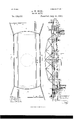
- Figure l is a plan diagram of a bridge and gates.
- Fig. 2 is an elevation of same, the bridge-lock inclines being in section to show the bridge-latch in its notch.
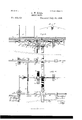
- Fig. 3 is a sectional elevation of one end et' the bridge and the adjacent approach, showing the mechanism and indicating the exitgates as open and the admission-gates as closed.
- Fig. 4. ⁇ is a plan showing the same ⁇ the flooring and other parts being removed to expose the mechanism.
- Fig. 5 shows the form of latch commonly used.
- l is the floor of the bridge, and 2 the floor of the approach.
- ll are prolongations of the latch-bars, for a purpose to be presently described.
- l2 is a lever located at a convenient point upon t-he bridge and connected by cords 13 to the latches to raise the latter out of their notches when it is desired te swing the bridge.
- 1i are the gates through which teams and foot-passengers are admitted to the bridge
- l5 are the gates through which they leave the bridge.
- These gates are each connected to a vertical arbor 16, which is provided at its lowerend beneath the floor with a pinion 17.
- the gates are arranged in pairs operated together, the footway and roadway gates constitutingapair.
- a toothed bar or rack 18 Between the piuions of each pair of gates, and meshing therewith, is a toothed bar or rack 18, which is arranged to slide back and forth in suitable guides to open and close the gates.
- On the bridge end of each rack-bar is a buffer 19.
- 2O are sliding bars, each provided with a buffer 2l, arranged on the bridge so as to register with bars 18 when the bridge is closed. These bars 2O are operated by two levers 22, placed at a convenient point on the bridge, and are connected thereto by links 23 and rock-shafts and arms 24. Each lever operates two bars at diagonally-opposite corners of the bridge, so that the gates at diagonallyopposite corners will be moved together.
- the gates are operated as follows: The bars 20, being moved outward bythe levers 2.2,impinge against rack-bars 18 and force them back, thus opening the gates. Vhen the bars V2O are retracted, the gates are automatically closed by weights 25, acting through the cords 2G, passing over pulleys 27 and connected to the rack-bars IS, so as to draw the latter forward again.
- 2S is a shaftjournaled in hangers 29 under the bridge approach.
- arms 30 At about the middle of this shaft,'and connected thereto, are two arms, one 30 provided with a counter-balance 3l and the other 32 provided with a pair of jaws 33.
- the arm 32 extends forward toward the bridge, so that the projecting tongue 1l on the bridge-latch is re- IOO ceivedbetween the jaws, and the latter are provided with laterally-flaring guides 34 to insure their engagement with said tongue.
- I claiml The combination, substantially as set forth, with a bridge, and gates at the ends thereof, and latches for holding the bridge in its closed position, of locking devices operated by the gate mechanism and adapted to lock the bridge-latches in holding position when the gates'are open, whereby it is impossible to open the bridge without first closing the gates.
Landscapes
- Holders For Apparel And Elements Relating To Apparel (AREA)
Description
2 Sheets-Sheet 1. A. W. BUEL.
BRIDGE GATE.
(No Model.)
Patented July 15,1891).
'ml oms Pneus co., Hom-mno., wAsHlNuYoN, n. c.
(No Model.) 2 SheetsV-Sheet 2.
A. VVv BUEL. BRIDGE GATE.
110.432,016. Patented July 15, 1890.
UNITED STATES PATENT OFFICE.
ALBERT IV. BUEL, OF MILIVAUKEE, VISCONSIN.
BRIDGE-GATE.
SPECIFICATION forming part of Letters Patent No. 432,016, dated July 15, 1890.
Application filed April l, 1890 Serial No. 346,206. (No model.)
To LZZ' whom' it 72mg/ concern:
Be it known that I, ALBERT YV. BUEL, of Milwaukee, Wisconsin, have invented certain new and useful Improvements in Bridge- Gates, of which the following is a specification.
Myinvention is int-ended more particularly for street-gates of draw-bridges; and it consists in so connecting the bridge andthe gates that the bridge cannot be opened until the gates are closed; also, in so connecting them that the gates cannot be opened until the bridge is closed; also, in so connecting them that the gates which admit teams and passengers to the bridge may be closed in advance of the others, thus permitting those upon the bridge to leave it, while preventing others coming upon it; also, in mechanism by which the gates may be operated by the person in charge of the bridge without his leaving it; also, in other matters hereinafter described, and set forth in the claims at the end hereof.
In the accompanying drawings I have illustrated my invention in what I consider its best form. It must be understood, however, that the specilic form of apparatus shown in the drawings is illustrative merely and not specific, except as herein otherwise stated.
In the drawings, Figure lis a plan diagram of a bridge and gates. Fig. 2 is an elevation of same, the bridge-lock inclines being in section to show the bridge-latch in its notch. Fig. 3 is a sectional elevation of one end et' the bridge and the adjacent approach, showing the mechanism and indicating the exitgates as open and the admission-gates as closed. Fig. 4.` is a plan showing the same` the flooring and other parts being removed to expose the mechanism. Fig. 5 shows the form of latch commonly used.
In the figures, l is the floor of the bridge, and 2 the floor of the approach.
3 is the turn-table, upon which the bridge swings.
4 is the bridge-latch, which locks it in its closed position. It is pivoted at 5 to a hanger (3 on the under side of the bridge, and is depressed by a spring 7.
8 are the inclined ways leading up te the notches 9, into which the latch-bars engage when the bridge is shut.
lO are friction-rollers en the latch-bars.
ll are prolongations of the latch-bars, for a purpose to be presently described.
l2 is a lever located at a convenient point upon t-he bridge and connected by cords 13 to the latches to raise the latter out of their notches when it is desired te swing the bridge.
1i are the gates through which teams and foot-passengers are admitted to the bridge, and l5 are the gates through which they leave the bridge. These gates are each connected to a vertical arbor 16, which is provided at its lowerend beneath the floor with a pinion 17. The gates are arranged in pairs operated together, the footway and roadway gates constitutingapair. Between the piuions of each pair of gates, and meshing therewith, is a toothed bar or rack 18, which is arranged to slide back and forth in suitable guides to open and close the gates. On the bridge end of each rack-bar is a buffer 19.
2O are sliding bars, each provided with a buffer 2l, arranged on the bridge so as to register with bars 18 when the bridge is closed. These bars 2O are operated by two levers 22, placed at a convenient point on the bridge, and are connected thereto by links 23 and rock-shafts and arms 24. Each lever operates two bars at diagonally-opposite corners of the bridge, so that the gates at diagonallyopposite corners will be moved together.
The gates are operated as follows: The bars 20, being moved outward bythe levers 2.2,impinge against rack-bars 18 and force them back, thus opening the gates. Vhen the bars V2O are retracted, the gates are automatically closed by weights 25, acting through the cords 2G, passing over pulleys 27 and connected to the rack-bars IS, so as to draw the latter forward again.
To prevent the bridge being opened except when the gates are all closed, and to prevent the gates being opened except when the bridge is closed and latched, I make use of the following mechanism, viz: 2S is a shaftjournaled in hangers 29 under the bridge approach. At about the middle of this shaft,'and connected thereto, are two arms, one 30 provided with a counter-balance 3l and the other 32 provided with a pair of jaws 33. The arm 32 extends forward toward the bridge, so that the projecting tongue 1l on the bridge-latch is re- IOO ceivedbetween the jaws, and the latter are provided with laterally-flaring guides 34 to insure their engagement with said tongue. At the ends of said shaft 28 and under each of the bars 18 is an arm 35, and there is an arm 36 on each of the bars 18 in position to engage the arms 35. This mechanism is duplicated at the two ends of the bridge, as shown in Fig. 2. Its operation is as follows: The parts being in the position shown in Fig. 3 in full lines, with the bridge closed and the gates open, the bridge-latch cannot be raised out of its notch without raising the jaws 33, and the latter cannot be raised while the gates are open, because the arm 35 stops against the arm 36. lf, now, all the gates be closed, the arms 36 are all moved forward to the position indicated by dotted lines, Fig. 3, thus freeing arms 35 and the jaws, and the latter may be raised by raising the latch,aud the bridge be swung. Vhile the bridge is open the jaws are held in their raised position by counterbalance 31, and arms 35 are held up with their endsin the path of arms 36, thus preventing the latter, and with them bars l8,from being moved back, and consequently the gates cannot be opened. When the bridge is closed again and its latch drops into notch 9 under the influence of spring 7, the jaws are movedy down by it and the gates are freed and can be opened. Until, however, thelatch drops into its notch and the bridge is securelyloeked in its closed position the jaws remain up and the gates must remain closed.
I claiml. The combination, substantially as set forth, with a bridge, and gates at the ends thereof, and latches for holding the bridge in its closed position, of locking devices operated by the gate mechanism and adapted to lock the bridge-latches in holding position when the gates'are open, whereby it is impossible to open the bridge without first closing the gates.
2. The combination, substantially as set forth, of a bridge with gates at the ends thereof, and locking devices operated by the bridge-latches to release the gates, whereby it is impossible to open the gates unless the bridge is closed and latched in that position.
3. The combination, substantially as set forth, with a swinging bridge and its latch and swinging gates and their operating-bars, of arms on the gate-bars, jaws adapted to engage the bridge-latch, and arms actuated by said jaws and adapted to engage the gate-bar arms, thereby holding the bridge-latch in locking position when the gates are open and locking the gates in closed position when the bridge is open.
4. The combination, substantially as set forth,of the swinging gates and their operating-bars, the bridge, the sliding bars upon the bridge, adapted to impinge against and move the gate bars, and two handles upon the bridge, one connected to each diagonally-opposite pair of bars, whereby either of the diagonally-opposite set of gates may be operated independently of the others.
ALBERT W. BUEL.
Witnesses:
I. N. TICHENOR, W. D. PATTERSON.
Publications (1)
| Publication Number | Publication Date |
|---|---|
| US432016A true US432016A (en) | 1890-07-15 |
Family
ID=2500921
Family Applications (1)
| Application Number | Title | Priority Date | Filing Date |
|---|---|---|---|
| US432016D Expired - Lifetime US432016A (en) | Bridge-gate |
Country Status (1)
| Country | Link |
|---|---|
| US (1) | US432016A (en) |
-
0
- US US432016D patent/US432016A/en not_active Expired - Lifetime
Similar Documents
| Publication | Publication Date | Title |
|---|---|---|
| US432016A (en) | Bridge-gate | |
| US795539A (en) | Hinge. | |
| US620441A (en) | Automatic gate | |
| US180706A (en) | Improvement in mechanisms for operating sliding doors | |
| US363257A (en) | Bridge-gate | |
| US456974A (en) | William richard white | |
| US770968A (en) | Gate-latch. | |
| US120573A (en) | Improvement in gates | |
| US762455A (en) | Lock for elevator-doors. | |
| US1079047A (en) | Locking mechanism. | |
| US295674A (en) | rathbun | |
| US262783A (en) | Hatchway-door-operating mechanism | |
| US696589A (en) | Bridge-gate. | |
| US472522A (en) | ross carpenter | |
| US776073A (en) | Latch. | |
| US755271A (en) | Gate. | |
| US497041A (en) | Lock or latch for elevator or other doors | |
| US725039A (en) | Gate. | |
| US329056A (en) | Jackson lane | |
| US769784A (en) | Gate. | |
| US660807A (en) | Gate. | |
| US727528A (en) | Farm-gate. | |
| US366832A (en) | Heaton | |
| US594385A (en) | Tilting gate | |
| US840754A (en) | Elevator-door-opening device. |