US4313294A - Constant float attachment apparatus - Google Patents
Constant float attachment apparatus Download PDFInfo
- Publication number
- US4313294A US4313294A US06/186,353 US18635380A US4313294A US 4313294 A US4313294 A US 4313294A US 18635380 A US18635380 A US 18635380A US 4313294 A US4313294 A US 4313294A
- Authority
- US
- United States
- Prior art keywords
- machine
- arm
- pivot
- pivot arm
- attachment
- Prior art date
- Legal status (The legal status is an assumption and is not a legal conclusion. Google has not performed a legal analysis and makes no representation as to the accuracy of the status listed.)
- Expired - Lifetime
Links
Images

Classifications
-
- A—HUMAN NECESSITIES
- A01—AGRICULTURE; FORESTRY; ANIMAL HUSBANDRY; HUNTING; TRAPPING; FISHING
- A01D—HARVESTING; MOWING
- A01D41/00—Combines, i.e. harvesters or mowers combined with threshing devices
- A01D41/12—Details of combines
- A01D41/14—Mowing tables
- A01D41/145—Header lifting devices
-
- Y—GENERAL TAGGING OF NEW TECHNOLOGICAL DEVELOPMENTS; GENERAL TAGGING OF CROSS-SECTIONAL TECHNOLOGIES SPANNING OVER SEVERAL SECTIONS OF THE IPC; TECHNICAL SUBJECTS COVERED BY FORMER USPC CROSS-REFERENCE ART COLLECTIONS [XRACs] AND DIGESTS
- Y10—TECHNICAL SUBJECTS COVERED BY FORMER USPC
- Y10S—TECHNICAL SUBJECTS COVERED BY FORMER USPC CROSS-REFERENCE ART COLLECTIONS [XRACs] AND DIGESTS
- Y10S56/00—Harvesters
- Y10S56/09—Detachable implement
-
- Y—GENERAL TAGGING OF NEW TECHNOLOGICAL DEVELOPMENTS; GENERAL TAGGING OF CROSS-SECTIONAL TECHNOLOGIES SPANNING OVER SEVERAL SECTIONS OF THE IPC; TECHNICAL SUBJECTS COVERED BY FORMER USPC CROSS-REFERENCE ART COLLECTIONS [XRACs] AND DIGESTS
- Y10—TECHNICAL SUBJECTS COVERED BY FORMER USPC
- Y10S—TECHNICAL SUBJECTS COVERED BY FORMER USPC CROSS-REFERENCE ART COLLECTIONS [XRACs] AND DIGESTS
- Y10S56/00—Harvesters
- Y10S56/10—Uneven terrain compensation
Definitions
- This invention relates generally to forage harvesters and more particularly to those including a floating attachment.
- Crop harvesting attachments are removably connected to harvesting machines such as forage harvesters. It is desirable to have the attachment "float" along the ground surface. This is accomplished by tensioning a spring or springs to a desired preload so that most of the weight of the attachment is suspended and only a fraction of the actual weight of the attachment rests on the ground. Thus, the effective ground engaging weight of the attachment is minimized.
- the ground surface is uneven and impact loads are forced on the attachment. Such impact loads could cause structural damage if the impact encountered the full weight of the attachment. However, since the impact encounters only a fraction of the actual weight of the attachment, damage is minimized. Another reason this is advantageous is because it is quite obviously easier to move the attachment along the ground when its effective ground engaging weight has been minimized.
- a limitation of known attachment flotation is that the amount of flotation preload decreases rapidly as the attachment is either forced upwardly or is raised mechanically. This limitation occurs because the spring is usually relaxed as the attachment moves upwardly. The situation is compounded since the torque about the attachment pivot point is increased due to the attachment CG moving away from the pivot point. As a result, when the attachment is only a few inches above the ground surface, its effective ground engaging weight is significantly increased.
- a substantially constant float attachment apparatus including a lift arm pivotally connected to pivot the lift arm.
- a pivot arm is operably connected, at one end, to the lift arm and at another end to a resilient member attached to the machine.
- the pivot arm is movable into and out of engagement with a stop.
- pivotal linkage relationships of the foregoing elements connected in series provide a means for maintaining a substantially constant flotation on the attachment during lifting and flotation operations.
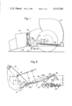
- FIG. 1 is a partial side elevational view illustrating a crop harvesting machine, an associated attachment and the apparatus of this invention
- FIGS. 2, 3 and 4 are partial graphic views illustrating pivotal linkage relationships of the apparatus of this invention.
- FIG. 5 is a graphic view illustrating advantages of the apparatus of this invention.
- FIG. 1 illustrates the constant flotation attachment apparatus of this invention generally designated 10 and operably connected for use in combination with a crop harvesting machine 12 and an associated attachment 14.
- attachment 14 is mounted on machine 12 at a pair of lift arms 16, only one of which is shown and described.
- Such lift arms 16 are usually operable to be pivotally movable about a pivot point 18 for lifting attachment 14 relative to the ground surface 20.
- Such lifting is generally accomplished by a fluid operated member 22, preferably a hydraulic cylinder 22a having a relatively movable piston 22b.
- Member 22 is connected to a well known hydraulic system on machine via a pair of conduits 24.
- piston 22b may be moved relative to cylinder 22a or may be maintained in a stationary position so that cylinder 22a and piston 22b move as a unit without relative movement therebetween.
- Elements of this invention include the lift arm 16, fluid operated member 22, a pivot arm 26, resilient members 28 and a stop 30. These elements are connected in series for forming a substantially constant flotation apparatus. A set of these elements is operably associated with each lift arm 16, however, only one set is shown and described. An advantage of having a set of these elements associated with each lift arm is that each set functions independently which allows one side of the attachment to be raised and lowered relative to the other side.
- Lift arm 16 is of a generally known structure and function.
- Fluid operated member 22 is commercially available and is capable of handling a system pressure of about 2000 psi.
- one end 32 of member 22 is connected to lift arm 16 for pivoting lift arm 16 about pivot point 18.
- Another end 34 of member 22 is connected to an end 36 of a pivot arm 26 connected to machine 12 for pivotal movement about a pivot point 38.
- Another end 40 of pivot arm 26 is connected to resilient members 28.
- pivot arm 26 has a first distance D 1 between pivot point 38 and end 36.
- Pivot arm 26 has a second distance D 2 between pivot point 38 and end 40.
- Pivot arm 26 is preferably formed of steel suitable for use in the construction of farm machinery.
- Resilient members 28 are preferably a commercially available pair of concentric tension springs formed of a known suitable spring steel. It is preferred to use a pair of concentric springs to obtain the desired springload and spring rate in the available space, however, it is recognized that equivalent resilient members may be substituted.
- Springs 28 are adjustably connected to machine 12 at a bolt 42, FIGS. 1 and 4 for increasing spring tension thus obtaining the desired flotation.
- springs 28 are tensioned so that attachment 14 has about a 100 pound effective ground engaging weight.
- more flexibility can be achieved by providing a slot 46 adjacent end 40 of pivot arm 26.
- springs 28 can be connected to pivot arm 26 at various positions. In this manner, the operating characteristics of the apparatus can be substantially maintained when accommodating attachments of various size and weight.
- a moment arm d 1 is a distance between a vertical line through the CG of floating attachment 14 and a vertical line through pivot point 18.
- a moment arm d 2 is a distance between a vertical line through the CG of raised attachment 14.
- End 36 of pivot arm 26 is a fixed point permitting lift arm 16 and a line of force (F 1 ) through member 22 to move to a position P 1 wherein a moment arm d 3 is increased in length to a moment arm d 4 .
- K 1 reamins constant d 2 is greater than d 1 thus T 2 is greater than T 1
- d 4 is greater than d 3 . From the foregoing it can be seen that during the lifting mode, flotation remains substantially constant due to the relationship: K 1 d 3 ⁇ T 1 ; K 1 d 4 ⁇ T 2 .
- Attachment 14 is raised unintentionally during the flotation mode when abrupt ground engagement urges attachment 14 upward thus pivoting lift arm 16 so that the aforementioned relationships occur rendering T 2 greater than T 1 since d 2 is greater than d 1 .
- Pressure in member 22 limits relative movement between piston 22b and cylinder 22a so that member 22 moves as a unit or a solid member.
- a line of force F 2 through member 22 and end 36 of pivot arm 26 move to a position P 2 .
- moment arm d 6 is decreased in length from a moment arm d 5 and a line of force F 3 through springs 28 and end 40 of pivot arm 26 move to position P 2 ' as pivot arm 26 is pivoted away from stop 30.
- the length of springs 28 is reduced which effectively lessens tension in springs 28 and changes the spring rate to a reduced rate K 2 .
- moment arm d 7 is increased in length to moment arm d 8 .
- FIG. 5 graphically illustrates, as an example only, that when springs 28 are tensioned for flotation so that attachment 14 has an effective ground engaging weight of 100 pounds, prior art flotation devices might result in an attachment weight of about 500 pounds when attachment 14 is raised about 12 inches above ground level as illustrated by a theoretical curve X.
- another theoretical curve y illustrates that a goal is to maintain the ground engaging weight absolutely constant regardless of height of the attachment above the ground.
- the apparatus 10 of this invention renders the effective ground engaging weight substantially constant as illustrated by still another theoretical curve Z when related to curves X and Y.
- the graph of FIG. 5 is intended to be exemplary only and is presented solely to illustrate that, within a set of selected parameters, theoretical curve Z falls somewhere between theoretical curves X and Y.
Landscapes
- Life Sciences & Earth Sciences (AREA)
- Environmental Sciences (AREA)
- Agricultural Machines (AREA)
Abstract
Description
Claims (6)
Priority Applications (1)
| Application Number | Priority Date | Filing Date | Title |
|---|---|---|---|
| US06/186,353 US4313294A (en) | 1980-09-11 | 1980-09-11 | Constant float attachment apparatus |
Applications Claiming Priority (1)
| Application Number | Priority Date | Filing Date | Title |
|---|---|---|---|
| US06/186,353 US4313294A (en) | 1980-09-11 | 1980-09-11 | Constant float attachment apparatus |
Publications (1)
| Publication Number | Publication Date |
|---|---|
| US4313294A true US4313294A (en) | 1982-02-02 |
Family
ID=22684613
Family Applications (1)
| Application Number | Title | Priority Date | Filing Date |
|---|---|---|---|
| US06/186,353 Expired - Lifetime US4313294A (en) | 1980-09-11 | 1980-09-11 | Constant float attachment apparatus |
Country Status (1)
| Country | Link |
|---|---|
| US (1) | US4313294A (en) |
Cited By (26)
| Publication number | Priority date | Publication date | Assignee | Title |
|---|---|---|---|---|
| US4435946A (en) | 1981-10-14 | 1984-03-13 | Erickson Leland E | Multi-row crop harvesting attachment |
| US4441307A (en) * | 1983-08-30 | 1984-04-10 | Allis-Chalmers Corporation | Harvester header with floating cutter bar |
| US4742671A (en) * | 1987-08-17 | 1988-05-10 | New Holland Inc. | Crop harvesting machine base unit lift mechanism providing auxiliary height boost to crop gathering attachment |
| US4759173A (en) * | 1985-06-25 | 1988-07-26 | Claas Ohg | Self-propelling agricultural machine |
| US4869058A (en) * | 1987-09-18 | 1989-09-26 | Claas Ohg | Self-propelling agricultural machine |
| US5095600A (en) * | 1989-04-01 | 1992-03-17 | Allan David T | Paving breakers and supports therefor |
| US5327709A (en) * | 1993-03-12 | 1994-07-12 | Ford New Holland, Inc. | Adjustable header flotation mechanism |
| US5341628A (en) * | 1991-08-19 | 1994-08-30 | Schumacher Gustav | Control device for an oscillatingly supported machine structure of an agricultural machine |
| US5381645A (en) * | 1992-05-06 | 1995-01-17 | Schumacher; Gustav | Control for a structural assembly self-aligningly supported on an agricultural machine |
| DE19602222A1 (en) * | 1996-01-23 | 1997-07-24 | Fortschritt Erntemaschinen | Lifting and ground copying appliance for adaptor attached to self-propelled harvester |
| US5799483A (en) * | 1996-08-29 | 1998-09-01 | Voss; Douglas A. | Combine harvester header lateral levelling |
| US6560953B2 (en) * | 2000-06-27 | 2003-05-13 | Claas Saulgau Gmbh | Agricultural harvesting machine front attachment adapting device |
| US6655118B1 (en) | 2002-08-13 | 2003-12-02 | Vermeer Manufacturing Company | Suspension system |
| MY120640A (en) * | 1999-11-05 | 2005-11-30 | Thomson Licensing Sa | Video display with emission control. |
| US7950212B1 (en) | 2010-03-29 | 2011-05-31 | Cnh America Llc | Cutterbar support for a crop harvesting header |
| US20110232251A1 (en) * | 2010-03-29 | 2011-09-29 | Cnh America Llc | Cutterbar support for a crop harvesting header |
| US20130219846A1 (en) * | 2010-06-22 | 2013-08-29 | Didier O. M. Verhaeghe | Combine harvester with automatic hydraulic and electric header coupling |
| US20160150716A1 (en) * | 2014-11-27 | 2016-06-02 | Cnh Industrial America Llc | Agricultural Harvester |
| US9713305B2 (en) * | 2015-07-24 | 2017-07-25 | Deere & Company | Harvesting head support arrangement |
| US9968034B2 (en) * | 2015-05-29 | 2018-05-15 | Cnh Industrial America Llc | Header carrying structure for combine |
| US20180139888A1 (en) * | 2015-05-19 | 2018-05-24 | Mchale Engineering | Coupling apparatus for coupling an agricultural implement to a prime mover |
| US20190110397A1 (en) * | 2017-10-12 | 2019-04-18 | Deere & Company | Roll center for attachment frame control arms |
| US11032970B2 (en) | 2018-10-30 | 2021-06-15 | Deere & Company | Varying a hydraulic cylinder mechanical advantage to obtain smoother float pressure |
| US11234368B2 (en) * | 2019-12-23 | 2022-02-01 | Cnh Industrial America Llc | Cutter bar assembly for a harvester |
| US11350558B2 (en) * | 2019-11-26 | 2022-06-07 | Cnh Industrial America Llc | Harvester head support torque transfer mechanism |
| US11375658B2 (en) * | 2019-12-23 | 2022-07-05 | Cnh Industrial America Llc | System and method for leveling a cutter bar of a harvester |
Citations (5)
| Publication number | Priority date | Publication date | Assignee | Title |
|---|---|---|---|---|
| GB873947A (en) * | 1959-03-31 | 1961-08-02 | Bolinder Munktell | Improvements relating to resilient support means for the cutter table of combined harvesters |
| US3355865A (en) * | 1965-06-30 | 1967-12-05 | Sperry Rand Corp | Forage harvester |
| US3728851A (en) * | 1967-06-13 | 1973-04-24 | Antwerp F Van | Electric circuit for harvester automatic header control |
| US4099368A (en) * | 1976-08-06 | 1978-07-11 | International Harvester Company | Gathering unit control apparatus |
| USRE30056E (en) | 1975-01-24 | 1979-07-31 | Sperry Rand Corporation | Crop harvesting machine header suspension system |
-
1980
- 1980-09-11 US US06/186,353 patent/US4313294A/en not_active Expired - Lifetime
Patent Citations (5)
| Publication number | Priority date | Publication date | Assignee | Title |
|---|---|---|---|---|
| GB873947A (en) * | 1959-03-31 | 1961-08-02 | Bolinder Munktell | Improvements relating to resilient support means for the cutter table of combined harvesters |
| US3355865A (en) * | 1965-06-30 | 1967-12-05 | Sperry Rand Corp | Forage harvester |
| US3728851A (en) * | 1967-06-13 | 1973-04-24 | Antwerp F Van | Electric circuit for harvester automatic header control |
| USRE30056E (en) | 1975-01-24 | 1979-07-31 | Sperry Rand Corporation | Crop harvesting machine header suspension system |
| US4099368A (en) * | 1976-08-06 | 1978-07-11 | International Harvester Company | Gathering unit control apparatus |
Cited By (32)
| Publication number | Priority date | Publication date | Assignee | Title |
|---|---|---|---|---|
| US4435946A (en) | 1981-10-14 | 1984-03-13 | Erickson Leland E | Multi-row crop harvesting attachment |
| US4441307A (en) * | 1983-08-30 | 1984-04-10 | Allis-Chalmers Corporation | Harvester header with floating cutter bar |
| US4759173A (en) * | 1985-06-25 | 1988-07-26 | Claas Ohg | Self-propelling agricultural machine |
| US4742671A (en) * | 1987-08-17 | 1988-05-10 | New Holland Inc. | Crop harvesting machine base unit lift mechanism providing auxiliary height boost to crop gathering attachment |
| US4869058A (en) * | 1987-09-18 | 1989-09-26 | Claas Ohg | Self-propelling agricultural machine |
| US5095600A (en) * | 1989-04-01 | 1992-03-17 | Allan David T | Paving breakers and supports therefor |
| US5341628A (en) * | 1991-08-19 | 1994-08-30 | Schumacher Gustav | Control device for an oscillatingly supported machine structure of an agricultural machine |
| US5381645A (en) * | 1992-05-06 | 1995-01-17 | Schumacher; Gustav | Control for a structural assembly self-aligningly supported on an agricultural machine |
| US5327709A (en) * | 1993-03-12 | 1994-07-12 | Ford New Holland, Inc. | Adjustable header flotation mechanism |
| DE19602222A1 (en) * | 1996-01-23 | 1997-07-24 | Fortschritt Erntemaschinen | Lifting and ground copying appliance for adaptor attached to self-propelled harvester |
| DE19602222C2 (en) * | 1996-01-23 | 1999-08-05 | Case Harvesting Sys Gmbh | Lifting and soil copying device for adapters mounted on the front of self-propelled harvesting machines |
| US5799483A (en) * | 1996-08-29 | 1998-09-01 | Voss; Douglas A. | Combine harvester header lateral levelling |
| MY120640A (en) * | 1999-11-05 | 2005-11-30 | Thomson Licensing Sa | Video display with emission control. |
| US6560953B2 (en) * | 2000-06-27 | 2003-05-13 | Claas Saulgau Gmbh | Agricultural harvesting machine front attachment adapting device |
| US6655118B1 (en) | 2002-08-13 | 2003-12-02 | Vermeer Manufacturing Company | Suspension system |
| US20110232251A1 (en) * | 2010-03-29 | 2011-09-29 | Cnh America Llc | Cutterbar support for a crop harvesting header |
| US8051633B2 (en) | 2010-03-29 | 2011-11-08 | Cnh America Llc | Cutterbar adjustment support for a crop harvesting header |
| US7950212B1 (en) | 2010-03-29 | 2011-05-31 | Cnh America Llc | Cutterbar support for a crop harvesting header |
| US20130219846A1 (en) * | 2010-06-22 | 2013-08-29 | Didier O. M. Verhaeghe | Combine harvester with automatic hydraulic and electric header coupling |
| US9137946B2 (en) * | 2010-06-22 | 2015-09-22 | Cnh Industrial America Llc | Combine harvester with automatic hydraulic and electric header coupling |
| US9730375B2 (en) * | 2014-11-27 | 2017-08-15 | Cnh Industrial America Llc | Agricultural harvester |
| US20160150716A1 (en) * | 2014-11-27 | 2016-06-02 | Cnh Industrial America Llc | Agricultural Harvester |
| US20180139888A1 (en) * | 2015-05-19 | 2018-05-24 | Mchale Engineering | Coupling apparatus for coupling an agricultural implement to a prime mover |
| US10681853B2 (en) * | 2015-05-19 | 2020-06-16 | Mchale Engineering | Coupling apparatus for coupling an agricultural implement to a prime mover |
| US9968034B2 (en) * | 2015-05-29 | 2018-05-15 | Cnh Industrial America Llc | Header carrying structure for combine |
| US9713305B2 (en) * | 2015-07-24 | 2017-07-25 | Deere & Company | Harvesting head support arrangement |
| US20190110397A1 (en) * | 2017-10-12 | 2019-04-18 | Deere & Company | Roll center for attachment frame control arms |
| US10517215B2 (en) * | 2017-10-12 | 2019-12-31 | Deere & Company | Roll center for attachment frame control arms |
| US11032970B2 (en) | 2018-10-30 | 2021-06-15 | Deere & Company | Varying a hydraulic cylinder mechanical advantage to obtain smoother float pressure |
| US11350558B2 (en) * | 2019-11-26 | 2022-06-07 | Cnh Industrial America Llc | Harvester head support torque transfer mechanism |
| US11234368B2 (en) * | 2019-12-23 | 2022-02-01 | Cnh Industrial America Llc | Cutter bar assembly for a harvester |
| US11375658B2 (en) * | 2019-12-23 | 2022-07-05 | Cnh Industrial America Llc | System and method for leveling a cutter bar of a harvester |
Similar Documents
| Publication | Publication Date | Title |
|---|---|---|
| US4313294A (en) | Constant float attachment apparatus | |
| US4733523A (en) | Header flotation system for an agricultural machine | |
| US5157905A (en) | Support linkage for mounting a header on a support frame | |
| US5327709A (en) | Adjustable header flotation mechanism | |
| US5115628A (en) | Height control system for a cotton harvester | |
| US4622803A (en) | Header flotation | |
| US7869922B2 (en) | Method and apparatus to put a windrower header in the transport mode under specified conditions | |
| US9861035B2 (en) | Height of cut control system | |
| US3623304A (en) | Hydraulic system for supporting a harvester platform | |
| US3548570A (en) | Cutter blade continuously automatically adjustable responsive to change in resistance to its operation | |
| JPH11332346A (en) | Mower suspension equipment for lawnmowers | |
| US8701790B2 (en) | Vibratory plow assembly | |
| US9357691B2 (en) | Hydraulic arrangement for a lifting unit | |
| US4924943A (en) | Agricultural pulling machine with automatic pitch vibration damping mechanism | |
| US3768570A (en) | Tractor hydraulic lift system | |
| US10681853B2 (en) | Coupling apparatus for coupling an agricultural implement to a prime mover | |
| US2779145A (en) | Tractor mounted mower | |
| US20040140109A1 (en) | Three-point hitch having flotation | |
| EP0286736A1 (en) | Header flotation system for an agricultural machine | |
| US3312048A (en) | Combine with floating harvesting platform | |
| JPH0228655Y2 (en) | ||
| JPH0442974Y2 (en) | ||
| EP0039213A1 (en) | Turf maintenance machine | |
| EP0066905B1 (en) | Mower lifting mechanism | |
| CA1287222C (en) | Header flotation system for an agricultural machine |
Legal Events
| Date | Code | Title | Description |
|---|---|---|---|
| AS | Assignment |
Owner name: SPERRY CORPORATION, NEW HOLLAND, PENNSYLVANIA Free format text: ASSIGNMENT OF ASSIGNORS INTEREST;ASSIGNOR:MARTENAS WAYNE B.;REEL/FRAME:003815/0239 Effective date: 19800908 |
|
| STCF | Information on status: patent grant |
Free format text: PATENTED CASE |
|
| AS | Assignment |
Owner name: NEW HOLLAND INC., 500 DILLER AVE., NEW HOLLAND, PA Free format text: ASSIGNMENT OF ASSIGNORS INTEREST.;ASSIGNOR:SPERRY CORPORATION A CORP. OF DE;REEL/FRAME:004700/0042 Effective date: 19860326 Owner name: NEW HOLLAND INC., A CORP. OF DE,PENNSYLVANIA Free format text: ASSIGNMENT OF ASSIGNORS INTEREST;ASSIGNOR:SPERRY CORPORATION A CORP. OF DE;REEL/FRAME:004700/0042 Effective date: 19860326 |
|
| AS | Assignment |
Owner name: FORD NEW HOLLAND, INC., 500 DILLER AVENUE, NEW HOL Free format text: ASSIGNMENT OF ASSIGNORS INTEREST.;ASSIGNOR:NEW HOLLAND INC., A CORP. OF DE.;REEL/FRAME:004879/0501 Effective date: 19871222 Owner name: FORD NEW HOLLAND, INC., A CORP. OF DE., PENNSYLVAN Free format text: ASSIGNMENT OF ASSIGNORS INTEREST;ASSIGNOR:NEW HOLLAND INC., A CORP. OF DE.;REEL/FRAME:004879/0501 Effective date: 19871222 |
|
| AS | Assignment |
Owner name: BLUE LEAF I.P., INC., DELAWARE Free format text: ASSIGNMENT OF ASSIGNORS INTEREST;ASSIGNOR:FORD NEW HOLLAND, INC.;REEL/FRAME:007388/0102 Effective date: 19941215 |