US4312407A - Spring trip mechanism for plows - Google Patents
Spring trip mechanism for plows Download PDFInfo
- Publication number
- US4312407A US4312407A US06/110,220 US11022080A US4312407A US 4312407 A US4312407 A US 4312407A US 11022080 A US11022080 A US 11022080A US 4312407 A US4312407 A US 4312407A
- Authority
- US
- United States
- Prior art keywords
- standard
- link
- axis
- axes
- frame
- Prior art date
- Legal status (The legal status is an assumption and is not a legal conclusion. Google has not performed a legal analysis and makes no representation as to the accuracy of the status listed.)
- Expired - Lifetime
Links
Images


Classifications
-
- A—HUMAN NECESSITIES
- A01—AGRICULTURE; FORESTRY; ANIMAL HUSBANDRY; HUNTING; TRAPPING; FISHING
- A01B—SOIL WORKING IN AGRICULTURE OR FORESTRY; PARTS, DETAILS, OR ACCESSORIES OF AGRICULTURAL MACHINES OR IMPLEMENTS, IN GENERAL
- A01B61/00—Devices for, or parts of, agricultural machines or implements for preventing overstrain
- A01B61/04—Devices for, or parts of, agricultural machines or implements for preventing overstrain of the connection between tools and carrier beam or frame
- A01B61/044—Devices for, or parts of, agricultural machines or implements for preventing overstrain of the connection between tools and carrier beam or frame the connection enabling a yielding pivoting movement around a substantially horizontal and transverse axis
Definitions
- the present invention relates to an earthworking implement having a trip mechanism which includes an overcenter linkage incorporating a spring member.
- the trip mechanism for an earthworking implement includes a pair of interconnected links having their remote ends pivotally connected to the implement frame and tool standard, respectively, on first and second horizontal parallel axes.
- One of the links includes an elongated rigid part having a leaf spring rigidly secured to one end thereof.
- the leaf spring extends alongside the rigid part and terminates in a lower offset bearing portion which is pivotally connected by a pivot pin to the other link (which is rigid) on a third axis parallel to and disposed intermediate the first and second axes.
- a pair of cooperating abutments on the links are normally in engagement to limit relative pivotal movement of the links toward an overcenter position.
- the third axis is in an overcenter position relative to a line intersecting the first and second axes when the abutments are in engagement.
- the leaf spring deflects in the manner of a cantilevered beam when excessive working forces are imposed on the tool standard, causing the third axis to move from its locked, overcenter position to a tripped position on the opposite side of a line intersecting the first and second axes.
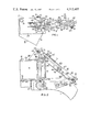
- FIG. 1 is a top view of a trip mechanism incorporating the present invention
- FIG. 2 is a side view of the trip mechanism shown in FIG. 1;
- FIG. 3 is a side view of the trip mechanism showing it subjected to excessive working forces causing the spring member of the trip mechanism to be deflected;
- FIG. 4 is a side view of the trip mechanism shown in a fully tripped condition
- FIG. 5 is a view taken along the line V--V in FIG. 2;
- FIG. 6 is a top view of a rigid part of one of the links of the trip mechanism
- FIG. 7 is a side view of the part shown in FIG. 6;
- FIG. 8 is a top view of the leaf spring component of one of the links which is normally attached to the rigid part shown in FIGS. 6 and 7;
- FIG. 9 is a side view of the leaf spring component shown in FIG. 8.
- a tool standard 11 is pivotally connected to a tubular diagonal frame member 12 of a plow frame 15 by pivot means in the form of a bolt 13 and nut 14 for vertical swinging movement about a horizontal transverse axis 16 which is transverse to the direction of travel of the plow during a working operation, which direction is indicated by arrow 17.
- the bolt 13 includes a shank part extending through an opening 21 in the upper end of the standard 11 and through aligned openings 22, 23 in transversely spaced vertical walls 24, 26 of a bracket 27 welded to a horizontal lower plate 28.
- the lower plate 28 and an upper plate 29 are rigidly secured to the tubular frame member 12 by releasable fastening means in the form of bolts 31 and nuts 32.
- a U-shaped bracket 36 is secured as by welding to upper plate 29 and includes a bearing sleeve 37 extending through aligned openings in the walls 38, 39 of the bracket 36. The outer ends of the sleeve are welded to the walls 38, 39.
- a trip mechanism 41 incorporating the present invention is interconnected between the bracket 36 of the plow frame 15 and a bracket 42 which is rigidly secured to the standard 11 by a pair of bolts 43 and nuts 44.
- the trip mechanism 41 normally maintains the standard 11 in an earthworking position, as illustrated in FIGS. 1 and 2, and trips, allowing the standard 11 to pivot upwardly to the fully tripped position shown in FIG. 4, when excessive working forces are imposed on the standard as when a buried boulder is encountered by the plow.
- the trip mechanism 41 which acts like an overcenter toggle linkage in maintaining the standard 11 in its working position, includes a rigid link 46 comprised of a pair of elongated plates 47, 48 interconnected by a cylindrical sleeve 49 and pin 51 extended therethrough and through aligned openings in the plates 47, 48.
- the pin is secured in its installed condition by a snap ring 52.
- the upper, forward ends of the plates 47, 48 of the rigid link 46 are pivotally connected to the bracket 36 of the frame 15 by a transverse pivot pin 53 for vertical swinging or pivotal movement about transverse horizontal axis 54.
- the pin 53 is held in place by a snap ring 56.
- the trip mechanism also includes a link 61 which comprises a rigid part 62, illustrated in detail in FIGS.
- the rigid part 62 includes a pair of spaced parallel plates 66, 67 rigidly interconnected by a spacer 68 welded to the confronting sides of the plates 66, 67.
- the upper front end of the rigid part 62 of the link 61 includes a transverse plate 71 welded at its transversely opposite sides to the upper end portions of plates 66, 67.
- the top of the plate slopes away from the plates 66, 67 in the rearward direction to accommodate deflection of the leaf spring 63 which is rigidly secured at its forward end to the front end of the rigid part 62 by a pair of bolts 72, 72' and nuts 73.
- the bolts 72, 72' extend through openings 74, 75 in the plate 71 of rigid part 62 and through openings 76, 77 in leaf spring 63.
- the lower, rear ends of the plates 66, 67 of the rigid part 62 are pivotally connected to bracket 42 of the standard 11 on a transverse horizontal axis 81 by a pivot pin 82 secured in place by a snap ring 83.
- the leaf spring 63 includes a flat deflectable part 63' extending downwardly and rearwardly from its rigidly but releasably secured attachment to the upper end of the rigid part 62 to a bearing portion in the form of a rolled end 86 presenting a cylindrical radially inner bearing surface 87 in cooperative pivotal bearing engagement with a transverse pivot pin 88.
- the bearing surface 87 and cooperative pivot pin 88 are disposed below the flat part of the leaf spring 63 so that when the spring 63 is subjected to tension loading, it will deflect upwardly at its rear end.
- the pivot pin 88 which is secured in place by a snap ring 89, pivotally connects the leaf spring 63 of the link 62 to the rear end of the rigid link 46 by virtue of it extending through aligned transverse openings in the rear ends of the plates 47, 48.
- the links 46 and 61 are pivotally interconnected for relative pivotal movement about a transverse toggle axis 91.
- the pin 88 extends freely through large aligned openings 92, 93 in the plates 66, 67 of the rigid part 62 of link 61.
- the holes 92, 93 are sufficiently large to accommodate movement of the pin relative to the rigid part 62 during a tripping operation.
- the trip mechanism 41 is in an overcenter position, that is, the axis 91 of pin 88 is below a line 94 intersecting axis 54 and axis 81.
- a pair of cooperating abutments in the form of the sleeve 49 and the head of bolt 72 engage to limit relative pivotal movement of the links 46, 61 in a downward direction during normal operations. As illustrated, the abutments are disposed intermediate the axes 54 and 91.
- the abutment represented by the head of bolt 72 may be adjusted by adding or removing one or more washers 97 from between the head of bolt 72 and the upper end of the link 61.
- the standard 11 When the plow encounters a large buried rock or the like, the standard 11 will be subjected to abnormally high working forces tending to pivot the standard rearwardly and upwardly about the pivot axis 16. These high working forces are resisted by the trip mechanism 41 and when they reach a predetermined magnitude, the leaf spring 63 deflects upwardly at its rolled end in the manner of a cantilevered beam, causing the pin 88 to move upwardly to the "in line” position shown in FIG. 3, wherein its axis 91 is centered on (coincides with) the line 94 through the axes 54 and 81. A slight additional working force on the standard 11 will move the pivot pin 88 upwardly beyond the "in line” position shown in FIG. 3 permitting the toggle to "break” or collapse to a tripped position as shown in FIG. 4.
- the operator can cause the plow to again be locked by its trip mechanism 41 in its working position by simply causing the plow frame 15 to be raised whereupon the plow will swing by gravity to its working position and the trip mechanism will reset in its overcenter position.
Landscapes
- Life Sciences & Earth Sciences (AREA)
- Engineering & Computer Science (AREA)
- Mechanical Engineering (AREA)
- Soil Sciences (AREA)
- Environmental Sciences (AREA)
- Agricultural Machines (AREA)
Priority Applications (2)
| Application Number | Priority Date | Filing Date | Title |
|---|---|---|---|
| US06/110,220 US4312407A (en) | 1980-01-07 | 1980-01-07 | Spring trip mechanism for plows |
| CA000360155A CA1139600A (fr) | 1980-01-07 | 1980-09-12 | Mecanisme releveur a ressort pour charrues |
Applications Claiming Priority (1)
| Application Number | Priority Date | Filing Date | Title |
|---|---|---|---|
| US06/110,220 US4312407A (en) | 1980-01-07 | 1980-01-07 | Spring trip mechanism for plows |
Publications (1)
| Publication Number | Publication Date |
|---|---|
| US4312407A true US4312407A (en) | 1982-01-26 |
Family
ID=22331853
Family Applications (1)
| Application Number | Title | Priority Date | Filing Date |
|---|---|---|---|
| US06/110,220 Expired - Lifetime US4312407A (en) | 1980-01-07 | 1980-01-07 | Spring trip mechanism for plows |
Country Status (2)
| Country | Link |
|---|---|
| US (1) | US4312407A (fr) |
| CA (1) | CA1139600A (fr) |
Cited By (10)
| Publication number | Priority date | Publication date | Assignee | Title |
|---|---|---|---|---|
| US4519461A (en) * | 1982-09-20 | 1985-05-28 | J. I. Case Company | Two-way plow with offset trips |
| US5072793A (en) * | 1990-08-02 | 1991-12-17 | Case Corporation | Trip assembly |
| US5197552A (en) * | 1990-10-19 | 1993-03-30 | Philip Di Maria | Collapsible bar assembly for agricultural equipment |
| US5323862A (en) * | 1991-07-08 | 1994-06-28 | Long Manufacturing N.C., Inc. | Moldboard plow trip |
| AU657702B2 (en) * | 1990-10-19 | 1995-03-23 | Philip Di Maria | Agricultural equipment |
| US5605196A (en) * | 1995-03-30 | 1997-02-25 | Case Corporation | Multi-piece subsoiler unit for an agricultural implement |
| US6105680A (en) * | 1999-05-28 | 2000-08-22 | Caterpillar S.A.R.L. | Locking device for a spring trip mechanism |
| US20150150186A1 (en) * | 2013-12-02 | 2015-06-04 | Fehr's Industrial Manufacturing, LLC | Plow with resettable plow bottom |
| RU2657737C1 (ru) * | 2017-06-27 | 2018-06-15 | Федеральное государственное бюджетное образовательное учреждение высшего образования "Горский государственный аграрный университет" | Секция плуга для каменистых почв |
| US10524404B2 (en) * | 2013-12-02 | 2020-01-07 | Fehr's Industrial Manufacturing, LLC | Plow with resettable plow bottom |
Citations (5)
| Publication number | Priority date | Publication date | Assignee | Title |
|---|---|---|---|---|
| US530819A (en) * | 1894-12-11 | Cultivator attachment | ||
| US3022835A (en) * | 1960-02-23 | 1962-02-27 | Int Harvester Co | Spring trip for plows |
| US3662839A (en) * | 1970-05-21 | 1972-05-16 | Massey Ferguson Inc | Earthworking implement |
| US3910354A (en) * | 1974-07-26 | 1975-10-07 | Int Harvester Co | Toggle trip for moldboard plow |
| US3972374A (en) * | 1974-12-23 | 1976-08-03 | J. I. Case Company | Trip mechanism for ground working implement |
-
1980
- 1980-01-07 US US06/110,220 patent/US4312407A/en not_active Expired - Lifetime
- 1980-09-12 CA CA000360155A patent/CA1139600A/fr not_active Expired
Patent Citations (5)
| Publication number | Priority date | Publication date | Assignee | Title |
|---|---|---|---|---|
| US530819A (en) * | 1894-12-11 | Cultivator attachment | ||
| US3022835A (en) * | 1960-02-23 | 1962-02-27 | Int Harvester Co | Spring trip for plows |
| US3662839A (en) * | 1970-05-21 | 1972-05-16 | Massey Ferguson Inc | Earthworking implement |
| US3910354A (en) * | 1974-07-26 | 1975-10-07 | Int Harvester Co | Toggle trip for moldboard plow |
| US3972374A (en) * | 1974-12-23 | 1976-08-03 | J. I. Case Company | Trip mechanism for ground working implement |
Cited By (11)
| Publication number | Priority date | Publication date | Assignee | Title |
|---|---|---|---|---|
| US4519461A (en) * | 1982-09-20 | 1985-05-28 | J. I. Case Company | Two-way plow with offset trips |
| US5072793A (en) * | 1990-08-02 | 1991-12-17 | Case Corporation | Trip assembly |
| US5197552A (en) * | 1990-10-19 | 1993-03-30 | Philip Di Maria | Collapsible bar assembly for agricultural equipment |
| AU657702B2 (en) * | 1990-10-19 | 1995-03-23 | Philip Di Maria | Agricultural equipment |
| US5323862A (en) * | 1991-07-08 | 1994-06-28 | Long Manufacturing N.C., Inc. | Moldboard plow trip |
| US5605196A (en) * | 1995-03-30 | 1997-02-25 | Case Corporation | Multi-piece subsoiler unit for an agricultural implement |
| US6105680A (en) * | 1999-05-28 | 2000-08-22 | Caterpillar S.A.R.L. | Locking device for a spring trip mechanism |
| US20150150186A1 (en) * | 2013-12-02 | 2015-06-04 | Fehr's Industrial Manufacturing, LLC | Plow with resettable plow bottom |
| US9936623B2 (en) * | 2013-12-02 | 2018-04-10 | Fehr's Industrial Manufacturing, LLC | Plow with resettable plow bottom |
| US10524404B2 (en) * | 2013-12-02 | 2020-01-07 | Fehr's Industrial Manufacturing, LLC | Plow with resettable plow bottom |
| RU2657737C1 (ru) * | 2017-06-27 | 2018-06-15 | Федеральное государственное бюджетное образовательное учреждение высшего образования "Горский государственный аграрный университет" | Секция плуга для каменистых почв |
Also Published As
| Publication number | Publication date |
|---|---|
| CA1139600A (fr) | 1983-01-18 |
Similar Documents
| Publication | Publication Date | Title |
|---|---|---|
| US4312407A (en) | Spring trip mechanism for plows | |
| US4825957A (en) | Breakaway mechanism for a row marker | |
| GB1591383A (en) | Implement having an earthworking tool | |
| US2944613A (en) | Spring release mounting for cultivator shank | |
| US4236583A (en) | Toggle link trip and reset mechanism for earthworking tool | |
| US4463813A (en) | Spring mounted standard assembly | |
| US4011915A (en) | Tool shank mounting assembly | |
| CA1136916A (fr) | Deracineur a tige pivotante | |
| US3972374A (en) | Trip mechanism for ground working implement | |
| US3517748A (en) | Two-way plow trip | |
| CA2126894C (fr) | Equipement pour labour profond et main de ressort | |
| US4116280A (en) | Spring reset mechanism | |
| CA1204319A (fr) | Motoculteur et dents pour celui-ci | |
| US3302728A (en) | Plow safety standard | |
| US3223175A (en) | Cultivator spring trip mounted assembly | |
| US4116281A (en) | Fast clamp chisel trip | |
| US3550690A (en) | Swinging beam plow | |
| US3274712A (en) | Retractable scarifier | |
| US5197552A (en) | Collapsible bar assembly for agricultural equipment | |
| US4425972A (en) | Split ring spring for earth working tool | |
| US2681813A (en) | Hitch for tractor mounted implements | |
| US2850957A (en) | Releasable plow standard | |
| US4730678A (en) | Heavy-duty trip mechanism for ground working implements | |
| US2712278A (en) | Implement frame trip | |
| US5323862A (en) | Moldboard plow trip |
Legal Events
| Date | Code | Title | Description |
|---|---|---|---|
| STCF | Information on status: patent grant |
Free format text: PATENTED CASE |
|
| AS | Assignment |
Owner name: CONNECTICUT NATIONAL BANK THE, A NATIONAL BANKING Free format text: SECURITY INTEREST;ASSIGNOR:ALLIS-CHALMERS CORPORATION A DE CORP.;REEL/FRAME:004149/0001 Effective date: 19830329 Owner name: WOODS KATHLEEN D., AS TRUSTEE Free format text: SECURITY INTEREST;ASSIGNOR:ALLIS-CHALMERS CORPORATION A DE CORP.;REEL/FRAME:004149/0001 Effective date: 19830329 |