US4312404A - Rotating blowout preventer - Google Patents
Rotating blowout preventer Download PDFInfo
- Publication number
- US4312404A US4312404A US06/145,716 US14571680A US4312404A US 4312404 A US4312404 A US 4312404A US 14571680 A US14571680 A US 14571680A US 4312404 A US4312404 A US 4312404A
- Authority
- US
- United States
- Prior art keywords
- housing
- bearing housing
- bearing
- rotatable sleeve
- bore
- Prior art date
- Legal status (The legal status is an assumption and is not a legal conclusion. Google has not performed a legal analysis and makes no representation as to the accuracy of the status listed.)
- Expired - Lifetime
Links
Images


Classifications
-
- E—FIXED CONSTRUCTIONS
- E21—EARTH DRILLING; MINING
- E21B—EARTH DRILLING, e.g. DEEP DRILLING; OBTAINING OIL, GAS, WATER, SOLUBLE OR MELTABLE MATERIALS OR A SLURRY OF MINERALS FROM WELLS
- E21B33/00—Sealing or packing boreholes or wells
- E21B33/02—Surface sealing or packing
- E21B33/08—Wipers; Oil savers
- E21B33/085—Rotatable packing means, e.g. rotating blow-out preventers
Definitions
- the field of this invention relates to oil well drilling devices and in particular to an improved rotating blowout preventer.
- the rotating blowout preventer In oil and gas well drilling, it is typical to mount a rotating blowout preventer on the top of a blowout preventer stack.
- the rotating blowout preventer generally serves several functions, including the sealing off of the kelly and the diverting of drilling mud into a recirculating mud line.
- the mounting of the rotating blowout preventer on the top of a blowout preventer stack locates the rotating blowout preventer just below the rotary table, thus putting it in a difficult position for access for repair.
- the size of a rotating blowout preventer is critical. Most known rotating blowout preventers have an upper, bearing housing which is too large to raise the blowout preventer upwardly through the rotary table for repair.
- the rotating blowout preventer of the preferred embodiment of this invention adapted to be mounted on a blowout preventer stack and located below the rotary drilling table in an oil well derrick.
- the rotating blowout preventer of the preferred embodiment of this invention includes a stationary housing adapted to be mounted on a blowout preventer stack, the stationary housing including a main bore adapted to receive a kelly or other piping.
- the stationary housing further includes a flowline housing portion adapted for connection to a recirculating mud line.
- a bearing housing which is generally cylindrical in configuration is mounted on the stationary housing and includes a bearing housing bore which is aligned with the main housing bore.
- a clamp means is provided for removably connecting together the bearing housing and the stationary housing.
- a rotatable sleeve is positioned within the bearing housing and a bearing means is positioned between the rotatable sleeve and the bearing housing for mounting the rotatable sleeve for rotation with respect to the bearing housing.
- a stripper rubber is attached to the bottom of the rotatable sleeve in one embodiment and is mounted concentrically within the rotatable sleeve in another embodiment.
- a seal means is provided for mounting between the bearing housing and rotatable sleeve to prevent well fluid from flowing therebetween.
- the rotatable sleeve and the bearing housing cooperate to provide a leak protection means to isolate the seal means from the bearing means and divert well fluid leaking past the seal means outwardly of the bearing housing.
- FIG. 1 is a schematic view of a drilling rig showing the position of the rotating blowout preventers of this invention in position for operation;
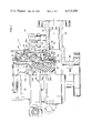
- FIG. 2 is a side view partly in section of the rotating blowout preventer of a preferred embodiment of this invention
- FIG. 3 is an exploded view of a portion of the seal means illustrating the sequential sealing operation of the seal rings of the seal means of the rotating blowout preventer of FIGS. 2 and 4;
- FIG. 4 is a side view partly in section of an alternate embodiment of the rotating blowout preventer of this invention.
- the letters R and R-1 represent the rotating blowout preventers of the preferred embodiments of this invention.
- the rotating blowout preventer R shown in detail in FIG. 2, is illustrated as being mounted for utilization in the drilling of an oil or a gas well.
- the letter D generally designates an oil well drilling derrick having a derrick floor F.
- a rotary table T is mounted into the derrick floor F.
- the rotary table T includes means for gripping and driving a kelly K which extends from a swivel (not shown) supported by the derrick D, through the rotary table T, the rotating blowout preventer R, and partly through a blowout preventer stack B into a driving connection with a drill string S.
- the kelly K is a multi-sided pipe member which is capable of being gripped by the rotary table T for a driving rotation of the drill string S, which drill string has mounted at the bottom the drill bit which actually drills the hole toward an anxiously anticipated oil reservoir.
- drilling fluid commonly known as "mud” is circulated downwardly through the kelly K and drill string S and outwardly at the bottom of the drill string and is then returned upwardly through the annular area between the drill string S and casing S through the blowout preventer stack B and finally through the rotating blowout preventer R outwardly into the recirculating mud line M.
- a rotating blowout preventer such as R
- One function is to receive and return the recirculating mud to the recirculating mud line M.
- Another function of the rotating blowout preventer R is to provide a rotating seal between the kelly K and a stationary housing to insure that none of the mud escapes or blows out through the derrick floor F.
- rotating blowout preventers R and R-1 of the preferred embodiments of this invention are particularly suited for assuming a minimum amount of height and diameter in their mounted position upon the blowout preventer stack B and additionally, are uniquely capable of being quickly repaired after removal upwardly through an opening in the rotary table T. It should be understood that the rotating blowout preventers R and R-1 of this invention may also be utilized with certain piping and tools as well as with the kelly K in providing a rotating seal and directing fluid flowing upwardly from the drilling bore hole.
- the rotating blowout preventer R includes a stationary housing generally designated as 10 having mounted thereon a bearing housing generally designated as 11. As clamping means 12 is provided for removably connecting the bearing housing 11 to the stationary housing 10.
- a rotatable sleeve 14 is mounted concentrically within the bearing housing 11 for rotation with respect thereto by a bearing means 15.
- a seal means 16 (illustrated in part in an exploded view in FIG. 3) is mounted with the bearing housing 11 in sealing engagement with the rotatable sleeve 14 to prevent well fluid from flowing between the bearing housing 11 and the rotatable sleeve 14.
- the rotatable sleeve 14 and the bearing housing 11 cooperate to provide a leak protection means generally designated as 17 to isolate the seal means 16 from the bearing means 15 and to divert well fluid leaking past the seal means outwardly of the bearing housing 11.
- the stationary housing 10 includes a main cylindrical section 20 having a main bore area 20a machined therein and a flowline housing section or portion 21 having a flowline bore area 21a machined therein.
- the main housing section 20 terminates at the bottom with a flange 20b which is adapted to be bolted to a corresponding flange on the top blowout preventer of stack B.
- the main stationary housing section 20 terminates in an upper clamping rim 20c which is engaged by the clamping means 12.
- the clamping rim 20c includes a downwardly facing, angled clamping shoulder 30b and an upwardly facing transverse annular face 20e.
- the main stationary housing section bore 20a may be defined as having a central axis 20f, which is transverse to the flowline housing portion bore axis 21b.
- the flowline housing portion 21 terminates in a flange 21c adapted to be bolted to the recirculating mud line M.
- the bearing housing 11 is generally cylindrical in configuration and has a bearing housing bore 11a having the same central axis 20f as the main stationary housing section bore 20a.
- the bearing housing 11 is also a stationary housing and includes a bottom annular face 11b and an exterior recessed portion 11c having clamping rim 11d machined therein.
- the clamping rim 11d includes an upwardly facing, tapered clamping shoulder 11e.
- the bearing housing 11 terminates at its upper end in several ears 11f having openings for receiving lifting hooks of any type.
- an upper, threaded portion 11g is joined to a bearing housing wall portion 11h.
- a series of internally directed shoulders form an internal rim 11i having another recess portion 11j which is formed by several internal wall portions.
- the internal rim 11i includes a circumferential recess or trough 22 having a plurality of radially directed ports or bores 51 machined therein to provide fluid communication between the circumferential recess 22 and the exterior of the bearing housing 11.
- the internal rim 11i further includes a downwardly facing shoulder 11k which is adapted to receive the seal means 16 as will be shortly described.
- the clamping means 12 is provided for removably attaching the bearing housing 11 to the stationary housing 10.
- the clamping means 12 includes a pin 25 which is mounted onto the top of the cylindrical portion of the flowline housing 21 of the stationary housing 10.
- Opposing semicircular clamping elements or members 26 and 27 are pivotally mounted onto the pin 25 for pivotal movement against the top clamping rim 20c of the stationary housing 10 and exterior clamping rim 11d of the bearing housing 11 for removably connecting the bearing housing 11 to the stationary housing 10.
- the semi-circular clamping member 26 terminates in vertically spaced locking lugs 26a and 26b.
- the semicircular clamping member 27 has a similar set of locking lugs which align with the locking lugs 26a and 26b when the two clamps are pivoted to the closed position of FIG. 2.
- the clamping members 26 and 27 are locked together by the swinging bolt 28 which is pivotally mounted onto pin 29 which extends through the locking lug set mounted on the clamping member 27.
- the bolt 28 is pivoted to the position shown in FIG. 2 and the nut 28a is then tightened down to drawn the clamping members 26 and 27 together.
- Each of the clamping members 26 and 27 includes an upper, inclined clamping shoulder 30a which engages the clamping face 11e on the bearing housing clamping rim 11d.
- Each of the clamping members 26 and 27 further includes the opposing, inclined clamping shoulders 30b which engage the top rim clamping face 20d on the stationary housing rim 20c.
- the clamping rim 11d as measured from its outermost point, has a smaller diameter than the top rim 20c on the stationary housing 10, if measured from its outermost point.
- the annular area of engagement between faces 11e and 30a has a clamping diameter which is less than the diameter of the annular area of engagement of faces 20d and 30b.
- the clamping member shoulder 11e actually provides effective clamping force within the outer bearing recess portion 11c.
- the positioning of the clamping members 26 and 27 at least partly within the outer bearing recess 11c allows the overall diameter of the bearing housing to be smaller than many of the known prior art products.
- the utilization of the upwardly inclined surfaces (as measured right to left) 11e and 30a in cooperation with the utilization of downwardly inclined clamping surfaces 30b and 20d serve to push the bearing housing rim 11d against the upper housing rim 20c thus providing force vectors which are both radial and vertical to press and maintain the bearing housing 11 against the stationary housing 10.
- the rotatable sleeve 14 is positioned within the bearing housing bore 20a and has a cylindrical inner wall 14a which forms a bore having a central axis 20f common to the bearing housing 11.
- the rotatable sleeve's interior wall 14a is a smooth cylinder.
- the upper part of the rotatable sleeve 14a includes a plurality of slots 14b which are adapted to receive the solid outside ring of a kelly drive unit in a known manner. In this manner, the rotatable sleeve 14 rotates with the kelly, which is driven by the rotary table T schematically illustrated in FIG. 1.
- the outside wall of the rotatable sleeve 14 includes a threaded portion 14c, a bearing wall portion 14d, a seal rim 14e and a seal face 14f.
- the seal rim 14e is formed by an upwardly facing transverse surface, an annular wall surface and a downwardly facing recessed area 14g.
- the downwardly facing recessed area 14g which forms the bottom part of the rim 14e is positioned adjacent to and just above the circumferential recess 22 on the bearing housing 11 and forms part of the leak protection means 17.
- a seal ring 33 is machined in an internal face of the bearing housing above the circumferential recess 22 for sealing engagement against the outside face of the seal rim 14e on the rotatable sleeve 14.
- the seal 33 acts to isolate the bearing means 15 from the seal means 16 and forms part of the seal protection means 17.
- a wear liner or sleeve 34 is mounted against the rotatable sleeve seal face 14f and forms part of the seal means generally designated at 16.
- Means generally designated as 35 are mounted onto the bottom of the rotatable sleeve 14 for the dual purpose of mounting the stripper rubber 38 and for mounting the wear sleeve 34 in slight compression.
- the mounting means 35 is a generally annular adapter plate 36 which is bolted onto the bottom of the rotatable sleeve 14 by a series of bolts such as 37.
- the annular upper face of the adapter plate 36 which actually abuts the bottom face of the rotatable sleeve 14 also engages the bottom of the wear sleeve 34, which fits against an upper shoulder 14g which adjoins the rotatable sleeve outer seal face 14f.
- the upper face engaging the wear sleeve 34 presses the wear sleeve 34 against an opposing shoulder on the rotatable sleeve 14 and compresses the wear sleeve in position against the sleeve face 14f.
- the wear sleeve 34 is mounted for rotation with the rotatable sleeve 14 and yet may be removed by removing the adapter plate 36 for easy replacement.
- it has generally been necessary to press fit a similar type of wear sleeve in position which means that the wear sleeve can only be removed by a much more difficult procedure which generally can only take place at a machine shop.
- the adapter plate 36 has bolted to the bottom thereof the stripper rubber 38 which is of a generally known configuration which narrows down to sealably fit against the kelly K, pipe or tool extending through the rotating blowout preventer R.
- the stripper rubber 38 in FIG. 1 is actually mounted below the rotatable sleeve 14 by the adapter plate 36 and effectively seals against the kelly K at interior sealing face 38a.
- the seal means 16 is mounted between the bearing housing 11 and the rotatable sleeve 14 to prevent the passage of fluid therebetween.
- the seal means 16 includes a packing support 40 which is L-shaped in the cross-sectional view of FIG. 2 and is of course generally cylindrical in its total configuration.
- the L-shaped packing support 40 includes a first portion 40a which is bolted to the bottom face 11b of the bearing housing 11 and a second portion 40b which extends upwardly and is positioned between the bearing housing 11 and the wear sleeve 34.
- the vertically, upwardly extending packing support portion 40b has mounted therein two O-ring seals which seal against adjacent faces of the internal recessed portion 11j of the bearing housing 11.
- Another ring-type of seal is located in the bottom face 11b of the bearing housing 11 for sealable engagement against the top face of the packing support portion 40a and against an annular face of the top stationary housing rim 20c.
- the vertical portion 40b of the L-shaped packing support 40 supports a sealing ring assembly generally designated as 41.
- the vertically oriented packing support portion 40b includes a sealing ring recess formed by internal shoulder 40c and the vertical internal face 40d.
- the sealing ring assembly 41 mounted therein includes a top packing ring 43, bottom packing ring 44 and intermediate packing rings 45 and 46, all of which are metal.
- Each of these packing rings include an O-ring such as 47 to sealably engage the packing surface support 40d.
- Mounted in between each of the metal packing rings are rubber packing elements 48, 49 and 50.
- the rubber packing element 48 includes a lower, inclined surface 48a against which fluid pressure acts to force inside packing ring face 48b against the rotating wear sleeve 34 thereby creating a seal therebetween.
- This shape of packing element is particularly useful because the pressure acts to cause the inside segment 48c of each packing element to flex to force the interior sealing face 48b against the wear sleeve 34.
- the packing rings 48, 49 and 50 are vertically spaced so that the rings effectively seal sequentially to thereby increase the effective life of the seal assembly 41.
- the lower packing ring 48 operates as the sealing ring to prevent the passage of fluid between the packing ring 48 and the wear sleeve 34 until it wears out or otherwise fails. At that time, pressure from the well leaks past the packing ring 48 and activates the seal ring 49.
- the leak protection means which has been generally designated by the number 17, includes a combination of structure found on the bearing housing 11 and on the rotatable sleeve 14, which structure cooperates to isolate the bearing means 15 from fluid leaking past the seal means 16 and divert any leaking fluid outwardly of the housing 11.
- the leaking well fluid is diverted outwardly of the housing 11 through flow of the fluid into the bearing housing recess or trough 22 and outwardly of the radial ports 51.
- An operator may look to the ports 51 from the outside to thereby aid in the determination as to the presence of a leak, which allows the leak protection means 17 to act as an early warning detector of problems with the seal assembly 16.
- the downwardly facing circumferential recess 14g formed in the rotatable sleeve rim 14e cooperates with the upwardly facing circumferential recess 22 in bearing housing rim 11i to form a circumferential passageway to confine leaking fluid thereto so that the leaking fluid will eventually flow out of the radial ports or bores 51.
- the seal 33 acts between the bearing housing 11 and the rim 14e of the rotatable sleeve 14 to prevent the passage of fluid into the area of the bearing means 15.
- the bearing means 15 is a standard thrust bearing 60 which may be of any suitable variety.
- the thrust bearing 60 is located between interior face 11h and the exterior bearing face 14d on the rotatable sleeve 14 in a bearing chamber 52 created by such faces, which bearing chamber is isolated from the seal means 16 below by the leak protection means 17, which includes the sealing ring 33.
- the bearing chamber 52 formed between faces 11h and 14d and isolated by seal 33 is further sealed off from the exterior by means of retainer rings 61 and 62.
- the retainer ring 61 is threadedly mounted to rotatable sleeve threaded area 14c, and the retainer ring 62 is threadedly mounted to the bearing housing internal threaded portion 11g.
- a seal 63 is located between the retainer rings 61 and 62 and O-ring seals are provided at the threaded connections between the retainer rings and the bearing housing and rotatable sleeve, respectively, to form the sealed bearing chamber 52, whose integrity is protected unless the retainer rings 61 and 62 are removed.
- An oil slinger ring 65 is mounted above the retainer rings 61 and 62 and is held in place by suitable set screws.
- the bearing chamber 52 in which the bearing 60 is mounted may be filled with oil through the bearing oil inlet 67. In this manner, the bearing 60 is sealed off from contamination, such isolation of the bearing 60 allowing for replacement of the bearing without contamination or removal of the seal means 16, and vice versa.
- the rotating blowout preventer R-1 is basically identical to the rotating blowout preventer R except that the rotating blowout preventer R-1 is designed even more compactly than the unit R.
- the overall height of the unit R-1 is less than the unit R.
- the overall diameter of the main cylindrical part of the R-1 unit may be even less than that of the unit R so that the R-1 unit can be even more easily removed through the rotary table.
- the rotating blowout preventer R-1 will now be described in only sufficient detail necessary to point out additional or different features of the R-1 unit over the unit R.
- the stationary housing 110 of unit R-1 again includes a main housing section 120 and a flowline housing section 121.
- a bearing housing 111 is removably mounted onto top rim 120c of the main housing section 120 by the clamping means 12.
- a rotatable sleeve 114 is mounted for sealed rotation within the bearing housing 11 by a bearing means generally designated as 115 and a seal means generally designated as 116.
- the rotatable sleeve 114 is formed of two internal vertical faces 101a and 101b joined by shoulder 101c.
- the rotatable sleeve 114 again provides a series of upwardly facing recesses 114b to receive a kelly drive unit.
- a retainer ring 161 is mounted onto an upper threaded portion 114c of the rotatable sleeve 114.
- a plurality of bolts mounts a stripper rubber mounting ring 102 onto the retainer ring 161.
- the stripper rubber retainer ring 102 extends downwardly into the inside of the rotatable sleeve 114 and engages rim 138b of the stripper rubber 138.
- the stripper rubber 138 is located concentrically within the rotatable sleeve 114 in order to make the unit R-1 even more compact than the unit R wherein the stripper rubber 38 depends downwardly from the rotatable sleeve 14.
- the wear sleeve 134 is again mounted on a wear sleeve face 114f of the rotatable sleeve 114 and provides part of the seal means 116.
- the seal means 116 differs from the seal means 16.
- the seal means 116 includes a horizontal portion 140a and a substantially vertically depending portion 140b.
- the horizontal portion 140a is bolted to the bottom of the bearing housing 111 while the vertical portion 140b depends downwardly therefrom and forms a ledge 140c which mounts packing ring assembly 141 thereon.
- the packing ring assembly 141 is identical to the packing ring assembly 41 of the unit R and thus sealably engages the wear sleeve 134 as illustrated in FIG. 4.
- the packing ring assembly support 140 depends down into and is intersected by the axis 121b of the flowline bore 120a of flowline housing portion 121. It is therefore clear that the seal means 116 is located at a relatively lower point in the housing bores 120a and 121b than was the seal assembly 16 for the unit R.
- the leak protection means 117 is basically identical to the leak protection means 17 of the unit R in that a circumferential recess 122 is machined into the bearing housing to cooperate with a downwardly facing circumferential recess 114g to provide a passageway to a plurality of circumferentially spaced radially directed ports 151.
- an additional hole 103 is machined in the cylindrical body portion 104 of the main housing portion 120 for allowing fluid leaking past the seal means 116 to flow outwardly not only of the bearing housing 111, but also outwardly of the stationary housing main portion 120.
- the radial bores 151 are located below the clamping means 112 in the unit R-1 as compared to the openings 51 of the unit R, which were located above the clamping means 12.
- the bearing housing 111 includes a bore 105 which extends vertically and horizontally into the packing ring assembly 141 in order to pressurize the packing ring assembly if desired.
- the bearing 160 for the bearing means or assembly 115 is basically mounted identically to the bearing means 15 of the unit R.
Abstract
Improved rotating blowout preventer including a stationary housing, a bearing housing and a bearing means assembly and seal assembly for mounting an internally located, rotating sleeve for rotating, sealable movement within the bearing housing. The bearing housing and rotatable sleeve cooperate to provide a circumferential passageway and radial ports to direct outwardly of the bearing housing any fluid which leaks past the seal assembly. The structure of the seal and bearing mountings provide for replacement of the seal without contaminating the bearing.
Description
The field of this invention relates to oil well drilling devices and in particular to an improved rotating blowout preventer.
In oil and gas well drilling, it is typical to mount a rotating blowout preventer on the top of a blowout preventer stack. The rotating blowout preventer generally serves several functions, including the sealing off of the kelly and the diverting of drilling mud into a recirculating mud line. Typically, the mounting of the rotating blowout preventer on the top of a blowout preventer stack locates the rotating blowout preventer just below the rotary table, thus putting it in a difficult position for access for repair. Generally speaking, it is necessary to remove most known rotating blowout preventers entirely from the blowout preventer stack from under the rotary table in order to gain access to the sealing assembly in order to repair or replace the sealing assembly. Removal of the entire rotating blowout preventer from under the rotary table is expensive and time consuming. Generally, it is necessary to replace the seal assembly on a rotating blowout preventer before replacing the bearings, unless the bearings have been contaminated as a result of the leakage through the seal assembly. And, in making repairs to the seal assembly, the possibility of having to replace not only the sealing assembly but also the bearings due to bearing contamination which may occur during repair makes repair of some types of rotating blowout preventers additionally expensive.
The size of a rotating blowout preventer is critical. Most known rotating blowout preventers have an upper, bearing housing which is too large to raise the blowout preventer upwardly through the rotary table for repair.
It is an object of this invention to provide a new and improved rotating blowout preventer which is capable of being removed through the rotary table and further is capable of seal maintenance separate from bearing maintenance.
These objects and other objects of this invention are carried out by the rotating blowout preventer of the preferred embodiment of this invention adapted to be mounted on a blowout preventer stack and located below the rotary drilling table in an oil well derrick. The rotating blowout preventer of the preferred embodiment of this invention includes a stationary housing adapted to be mounted on a blowout preventer stack, the stationary housing including a main bore adapted to receive a kelly or other piping. The stationary housing further includes a flowline housing portion adapted for connection to a recirculating mud line. A bearing housing which is generally cylindrical in configuration is mounted on the stationary housing and includes a bearing housing bore which is aligned with the main housing bore. A clamp means is provided for removably connecting together the bearing housing and the stationary housing. A rotatable sleeve is positioned within the bearing housing and a bearing means is positioned between the rotatable sleeve and the bearing housing for mounting the rotatable sleeve for rotation with respect to the bearing housing.
A stripper rubber is attached to the bottom of the rotatable sleeve in one embodiment and is mounted concentrically within the rotatable sleeve in another embodiment.
A seal means is provided for mounting between the bearing housing and rotatable sleeve to prevent well fluid from flowing therebetween. The rotatable sleeve and the bearing housing cooperate to provide a leak protection means to isolate the seal means from the bearing means and divert well fluid leaking past the seal means outwardly of the bearing housing.
The features of the new and improved rotating blowout preventer of this invention have only been generally described in this Summary. The specific features are set forth in the detailed specification as follows.
FIG. 1 is a schematic view of a drilling rig showing the position of the rotating blowout preventers of this invention in position for operation;
FIG. 2 is a side view partly in section of the rotating blowout preventer of a preferred embodiment of this invention;
FIG. 3 is an exploded view of a portion of the seal means illustrating the sequential sealing operation of the seal rings of the seal means of the rotating blowout preventer of FIGS. 2 and 4; and
FIG. 4 is a side view partly in section of an alternate embodiment of the rotating blowout preventer of this invention.
Referring to the drawings, the letters R and R-1 represent the rotating blowout preventers of the preferred embodiments of this invention. Referring to FIG. 1, the rotating blowout preventer R, shown in detail in FIG. 2, is illustrated as being mounted for utilization in the drilling of an oil or a gas well. Referring to FIG. 1, the letter D generally designates an oil well drilling derrick having a derrick floor F. A rotary table T is mounted into the derrick floor F. As is known in the art of oil and gas well drilling, the rotary table T includes means for gripping and driving a kelly K which extends from a swivel (not shown) supported by the derrick D, through the rotary table T, the rotating blowout preventer R, and partly through a blowout preventer stack B into a driving connection with a drill string S.
In a typical oil well drilling operation, the kelly K is a multi-sided pipe member which is capable of being gripped by the rotary table T for a driving rotation of the drill string S, which drill string has mounted at the bottom the drill bit which actually drills the hole toward an anxiously anticipated oil reservoir. Typically, drilling fluid, commonly known as "mud" is circulated downwardly through the kelly K and drill string S and outwardly at the bottom of the drill string and is then returned upwardly through the annular area between the drill string S and casing S through the blowout preventer stack B and finally through the rotating blowout preventer R outwardly into the recirculating mud line M.
The functions of a rotating blowout preventer such as R are therefore several. One function is to receive and return the recirculating mud to the recirculating mud line M. Another function of the rotating blowout preventer R is to provide a rotating seal between the kelly K and a stationary housing to insure that none of the mud escapes or blows out through the derrick floor F.
There are several known designs of rotating blowout preventers, some of which, as known to this inventor, have been described in the Background of the Invention and the accompanying Prior Art Statement. The rotating blowout preventers R and R-1 of the preferred embodiments of this invention are particularly suited for assuming a minimum amount of height and diameter in their mounted position upon the blowout preventer stack B and additionally, are uniquely capable of being quickly repaired after removal upwardly through an opening in the rotary table T. It should be understood that the rotating blowout preventers R and R-1 of this invention may also be utilized with certain piping and tools as well as with the kelly K in providing a rotating seal and directing fluid flowing upwardly from the drilling bore hole.
Referring now to FIG. 2, the rotating blowout preventer R will first be described. Basically, the rotating blowout preventer R includes a stationary housing generally designated as 10 having mounted thereon a bearing housing generally designated as 11. As clamping means 12 is provided for removably connecting the bearing housing 11 to the stationary housing 10. A rotatable sleeve 14 is mounted concentrically within the bearing housing 11 for rotation with respect thereto by a bearing means 15. A seal means 16 (illustrated in part in an exploded view in FIG. 3) is mounted with the bearing housing 11 in sealing engagement with the rotatable sleeve 14 to prevent well fluid from flowing between the bearing housing 11 and the rotatable sleeve 14. The rotatable sleeve 14 and the bearing housing 11 cooperate to provide a leak protection means generally designated as 17 to isolate the seal means 16 from the bearing means 15 and to divert well fluid leaking past the seal means outwardly of the bearing housing 11.
Referring in particular to FIG. 2, the stationary housing 10 includes a main cylindrical section 20 having a main bore area 20a machined therein and a flowline housing section or portion 21 having a flowline bore area 21a machined therein. The main housing section 20 terminates at the bottom with a flange 20b which is adapted to be bolted to a corresponding flange on the top blowout preventer of stack B. The main stationary housing section 20 terminates in an upper clamping rim 20c which is engaged by the clamping means 12. The clamping rim 20c includes a downwardly facing, angled clamping shoulder 30b and an upwardly facing transverse annular face 20e. The main stationary housing section bore 20a may be defined as having a central axis 20f, which is transverse to the flowline housing portion bore axis 21b. The flowline housing portion 21 terminates in a flange 21c adapted to be bolted to the recirculating mud line M.
The bearing housing 11 is generally cylindrical in configuration and has a bearing housing bore 11a having the same central axis 20f as the main stationary housing section bore 20a. The bearing housing 11 is also a stationary housing and includes a bottom annular face 11b and an exterior recessed portion 11c having clamping rim 11d machined therein. The clamping rim 11d includes an upwardly facing, tapered clamping shoulder 11e. The bearing housing 11 terminates at its upper end in several ears 11f having openings for receiving lifting hooks of any type.
Referring now to the interior wall portions of the bearing housing 11, an upper, threaded portion 11g is joined to a bearing housing wall portion 11h. A series of internally directed shoulders form an internal rim 11i having another recess portion 11j which is formed by several internal wall portions. The internal rim 11i includes a circumferential recess or trough 22 having a plurality of radially directed ports or bores 51 machined therein to provide fluid communication between the circumferential recess 22 and the exterior of the bearing housing 11. The internal rim 11i further includes a downwardly facing shoulder 11k which is adapted to receive the seal means 16 as will be shortly described.
The clamping means 12 is provided for removably attaching the bearing housing 11 to the stationary housing 10. The clamping means 12 includes a pin 25 which is mounted onto the top of the cylindrical portion of the flowline housing 21 of the stationary housing 10. Opposing semicircular clamping elements or members 26 and 27 are pivotally mounted onto the pin 25 for pivotal movement against the top clamping rim 20c of the stationary housing 10 and exterior clamping rim 11d of the bearing housing 11 for removably connecting the bearing housing 11 to the stationary housing 10. The semi-circular clamping member 26 terminates in vertically spaced locking lugs 26a and 26b. The semicircular clamping member 27 has a similar set of locking lugs which align with the locking lugs 26a and 26b when the two clamps are pivoted to the closed position of FIG. 2. The clamping members 26 and 27 are locked together by the swinging bolt 28 which is pivotally mounted onto pin 29 which extends through the locking lug set mounted on the clamping member 27. The bolt 28 is pivoted to the position shown in FIG. 2 and the nut 28a is then tightened down to drawn the clamping members 26 and 27 together. Each of the clamping members 26 and 27 includes an upper, inclined clamping shoulder 30a which engages the clamping face 11e on the bearing housing clamping rim 11d. Each of the clamping members 26 and 27 further includes the opposing, inclined clamping shoulders 30b which engage the top rim clamping face 20d on the stationary housing rim 20c. The clamping rim 11d, as measured from its outermost point, has a smaller diameter than the top rim 20c on the stationary housing 10, if measured from its outermost point. In a corresponding manner, the upper clamping surface 30a on the clamping members 26 and 27, as measured from its innermost point or face, has a smaller diameter than the opposing lower clamping surface 30b on the clamping members 26 and 27. Stated another way, the annular area of engagement between faces 11e and 30a has a clamping diameter which is less than the diameter of the annular area of engagement of faces 20d and 30b. In this manner, the clamping member shoulder 11e actually provides effective clamping force within the outer bearing recess portion 11c. The positioning of the clamping members 26 and 27 at least partly within the outer bearing recess 11c allows the overall diameter of the bearing housing to be smaller than many of the known prior art products. The utilization of the upwardly inclined surfaces (as measured right to left) 11e and 30a in cooperation with the utilization of downwardly inclined clamping surfaces 30b and 20d serve to push the bearing housing rim 11d against the upper housing rim 20c thus providing force vectors which are both radial and vertical to press and maintain the bearing housing 11 against the stationary housing 10.
The rotatable sleeve 14 is positioned within the bearing housing bore 20a and has a cylindrical inner wall 14a which forms a bore having a central axis 20f common to the bearing housing 11. The rotatable sleeve's interior wall 14a is a smooth cylinder. The upper part of the rotatable sleeve 14a includes a plurality of slots 14b which are adapted to receive the solid outside ring of a kelly drive unit in a known manner. In this manner, the rotatable sleeve 14 rotates with the kelly, which is driven by the rotary table T schematically illustrated in FIG. 1.
The outside wall of the rotatable sleeve 14 includes a threaded portion 14c, a bearing wall portion 14d, a seal rim 14e and a seal face 14f. The seal rim 14e is formed by an upwardly facing transverse surface, an annular wall surface and a downwardly facing recessed area 14g. The downwardly facing recessed area 14g which forms the bottom part of the rim 14e is positioned adjacent to and just above the circumferential recess 22 on the bearing housing 11 and forms part of the leak protection means 17.
A seal ring 33 is machined in an internal face of the bearing housing above the circumferential recess 22 for sealing engagement against the outside face of the seal rim 14e on the rotatable sleeve 14. The seal 33 acts to isolate the bearing means 15 from the seal means 16 and forms part of the seal protection means 17.
A wear liner or sleeve 34 is mounted against the rotatable sleeve seal face 14f and forms part of the seal means generally designated at 16.
Means generally designated as 35 are mounted onto the bottom of the rotatable sleeve 14 for the dual purpose of mounting the stripper rubber 38 and for mounting the wear sleeve 34 in slight compression. The mounting means 35 is a generally annular adapter plate 36 which is bolted onto the bottom of the rotatable sleeve 14 by a series of bolts such as 37. The annular upper face of the adapter plate 36 which actually abuts the bottom face of the rotatable sleeve 14 also engages the bottom of the wear sleeve 34, which fits against an upper shoulder 14g which adjoins the rotatable sleeve outer seal face 14f. When the adapter plate 36 is bolted in place, the upper face engaging the wear sleeve 34 presses the wear sleeve 34 against an opposing shoulder on the rotatable sleeve 14 and compresses the wear sleeve in position against the sleeve face 14f. In this manner, the wear sleeve 34 is mounted for rotation with the rotatable sleeve 14 and yet may be removed by removing the adapter plate 36 for easy replacement. In prior art products, it has generally been necessary to press fit a similar type of wear sleeve in position, which means that the wear sleeve can only be removed by a much more difficult procedure which generally can only take place at a machine shop.
The adapter plate 36 has bolted to the bottom thereof the stripper rubber 38 which is of a generally known configuration which narrows down to sealably fit against the kelly K, pipe or tool extending through the rotating blowout preventer R. The stripper rubber 38 in FIG. 1 is actually mounted below the rotatable sleeve 14 by the adapter plate 36 and effectively seals against the kelly K at interior sealing face 38a.
The seal means 16 is mounted between the bearing housing 11 and the rotatable sleeve 14 to prevent the passage of fluid therebetween. The seal means 16 includes a packing support 40 which is L-shaped in the cross-sectional view of FIG. 2 and is of course generally cylindrical in its total configuration. The L-shaped packing support 40 includes a first portion 40a which is bolted to the bottom face 11b of the bearing housing 11 and a second portion 40b which extends upwardly and is positioned between the bearing housing 11 and the wear sleeve 34. The vertically, upwardly extending packing support portion 40b has mounted therein two O-ring seals which seal against adjacent faces of the internal recessed portion 11j of the bearing housing 11. Another ring-type of seal is located in the bottom face 11b of the bearing housing 11 for sealable engagement against the top face of the packing support portion 40a and against an annular face of the top stationary housing rim 20c.
Referring to FIG. 3, the vertical portion 40b of the L-shaped packing support 40 supports a sealing ring assembly generally designated as 41. The vertically oriented packing support portion 40b includes a sealing ring recess formed by internal shoulder 40c and the vertical internal face 40d. The sealing ring assembly 41 mounted therein includes a top packing ring 43, bottom packing ring 44 and intermediate packing rings 45 and 46, all of which are metal. Each of these packing rings include an O-ring such as 47 to sealably engage the packing surface support 40d. Mounted in between each of the metal packing rings are rubber packing elements 48, 49 and 50. The rubber packing element 48 includes a lower, inclined surface 48a against which fluid pressure acts to force inside packing ring face 48b against the rotating wear sleeve 34 thereby creating a seal therebetween. This shape of packing element is particularly useful because the pressure acts to cause the inside segment 48c of each packing element to flex to force the interior sealing face 48b against the wear sleeve 34. The packing rings 48, 49 and 50 are vertically spaced so that the rings effectively seal sequentially to thereby increase the effective life of the seal assembly 41. Thus, the lower packing ring 48 operates as the sealing ring to prevent the passage of fluid between the packing ring 48 and the wear sleeve 34 until it wears out or otherwise fails. At that time, pressure from the well leaks past the packing ring 48 and activates the seal ring 49.
After each of the seal rings 48, 49 and 50 have partially or fully failed, well fluid leaks upwardly between the interior bearing housing rim 11i and the rotatable sleeve 14 and leaks into the circumferential recess 22 machined in the bearing housing rim 11i. The upper circumferential recess or trough 14g in the rotatable sleeve 14 serves to confine and direct any leaking fluid down into the circumferential bearing housing recess 14g. The leaking fluid flows from the circumferential recess 14g outwardly through one or more of a series of circumferentially spaced, radially directed ports 51, thereby avoiding clogging or caking of drilling fluid in the area between the bearing housing and the rotating sleeve.
Thus the leak protection means, which has been generally designated by the number 17, includes a combination of structure found on the bearing housing 11 and on the rotatable sleeve 14, which structure cooperates to isolate the bearing means 15 from fluid leaking past the seal means 16 and divert any leaking fluid outwardly of the housing 11. The leaking well fluid is diverted outwardly of the housing 11 through flow of the fluid into the bearing housing recess or trough 22 and outwardly of the radial ports 51. An operator may look to the ports 51 from the outside to thereby aid in the determination as to the presence of a leak, which allows the leak protection means 17 to act as an early warning detector of problems with the seal assembly 16. The downwardly facing circumferential recess 14g formed in the rotatable sleeve rim 14e cooperates with the upwardly facing circumferential recess 22 in bearing housing rim 11i to form a circumferential passageway to confine leaking fluid thereto so that the leaking fluid will eventually flow out of the radial ports or bores 51. The seal 33 acts between the bearing housing 11 and the rim 14e of the rotatable sleeve 14 to prevent the passage of fluid into the area of the bearing means 15.
The bearing means 15 is a standard thrust bearing 60 which may be of any suitable variety. The thrust bearing 60 is located between interior face 11h and the exterior bearing face 14d on the rotatable sleeve 14 in a bearing chamber 52 created by such faces, which bearing chamber is isolated from the seal means 16 below by the leak protection means 17, which includes the sealing ring 33. The bearing chamber 52 formed between faces 11h and 14d and isolated by seal 33 is further sealed off from the exterior by means of retainer rings 61 and 62. The retainer ring 61 is threadedly mounted to rotatable sleeve threaded area 14c, and the retainer ring 62 is threadedly mounted to the bearing housing internal threaded portion 11g. A seal 63 is located between the retainer rings 61 and 62 and O-ring seals are provided at the threaded connections between the retainer rings and the bearing housing and rotatable sleeve, respectively, to form the sealed bearing chamber 52, whose integrity is protected unless the retainer rings 61 and 62 are removed. An oil slinger ring 65 is mounted above the retainer rings 61 and 62 and is held in place by suitable set screws. The bearing chamber 52 in which the bearing 60 is mounted may be filled with oil through the bearing oil inlet 67. In this manner, the bearing 60 is sealed off from contamination, such isolation of the bearing 60 allowing for replacement of the bearing without contamination or removal of the seal means 16, and vice versa.
Referring now to FIG. 3, the rotating blowout preventer R-1 is basically identical to the rotating blowout preventer R except that the rotating blowout preventer R-1 is designed even more compactly than the unit R. The overall height of the unit R-1 is less than the unit R. In addition, the overall diameter of the main cylindrical part of the R-1 unit may be even less than that of the unit R so that the R-1 unit can be even more easily removed through the rotary table. The rotating blowout preventer R-1 will now be described in only sufficient detail necessary to point out additional or different features of the R-1 unit over the unit R.
The stationary housing 110 of unit R-1 again includes a main housing section 120 and a flowline housing section 121. A bearing housing 111 is removably mounted onto top rim 120c of the main housing section 120 by the clamping means 12.
A rotatable sleeve 114 is mounted for sealed rotation within the bearing housing 11 by a bearing means generally designated as 115 and a seal means generally designated as 116. The rotatable sleeve 114 is formed of two internal vertical faces 101a and 101b joined by shoulder 101c. The rotatable sleeve 114 again provides a series of upwardly facing recesses 114b to receive a kelly drive unit. A retainer ring 161 is mounted onto an upper threaded portion 114c of the rotatable sleeve 114. A plurality of bolts mounts a stripper rubber mounting ring 102 onto the retainer ring 161. The stripper rubber retainer ring 102 extends downwardly into the inside of the rotatable sleeve 114 and engages rim 138b of the stripper rubber 138. In the embodiment R-1, the stripper rubber 138 is located concentrically within the rotatable sleeve 114 in order to make the unit R-1 even more compact than the unit R wherein the stripper rubber 38 depends downwardly from the rotatable sleeve 14.
The wear sleeve 134 is again mounted on a wear sleeve face 114f of the rotatable sleeve 114 and provides part of the seal means 116. The seal means 116 differs from the seal means 16. The seal means 116 includes a horizontal portion 140a and a substantially vertically depending portion 140b. The horizontal portion 140a is bolted to the bottom of the bearing housing 111 while the vertical portion 140b depends downwardly therefrom and forms a ledge 140c which mounts packing ring assembly 141 thereon. The packing ring assembly 141 is identical to the packing ring assembly 41 of the unit R and thus sealably engages the wear sleeve 134 as illustrated in FIG. 4. Here, the packing ring assembly support 140 depends down into and is intersected by the axis 121b of the flowline bore 120a of flowline housing portion 121. It is therefore clear that the seal means 116 is located at a relatively lower point in the housing bores 120a and 121b than was the seal assembly 16 for the unit R.
The leak protection means 117 is basically identical to the leak protection means 17 of the unit R in that a circumferential recess 122 is machined into the bearing housing to cooperate with a downwardly facing circumferential recess 114g to provide a passageway to a plurality of circumferentially spaced radially directed ports 151. In the unit R-1, an additional hole 103 is machined in the cylindrical body portion 104 of the main housing portion 120 for allowing fluid leaking past the seal means 116 to flow outwardly not only of the bearing housing 111, but also outwardly of the stationary housing main portion 120. It is noted that the radial bores 151 are located below the clamping means 112 in the unit R-1 as compared to the openings 51 of the unit R, which were located above the clamping means 12.
The bearing housing 111 includes a bore 105 which extends vertically and horizontally into the packing ring assembly 141 in order to pressurize the packing ring assembly if desired. The bearing 160 for the bearing means or assembly 115 is basically mounted identically to the bearing means 15 of the unit R.
The foregoing disclosure and description of the invention are illustrative and explanatory thereof, and various changes in the size, shape and materials as well as in the details of the illustrated construction may be made without departing from the spirit of the invention.
Claims (7)
1. A new and improved rotating blowout preventer adapted to be mounted on a blowout preventer stack located below a rotating drilling table in an oil well derrick floor, comprising:
a stationary housing adapted to be mounted on a blowout preventer stack, said stationary housing including a main bore adapted to receive a kelly or other piping;
said stationary housing further including a flowline housing portion adapted for connection to a recirculating flowline, said flowline housing having a bore directed transversely to the main stationary housing bore;
a bearing housing generally cylindrical in configuration and having a bearing housing bore axially aligned with said main stationary housing bore;
clamp means for removably connecting said bearing housing to said stationary housing;
a rotatable sleeve positioned within said bearing housing bore and bearing means positioned between said rotatable sleeve and said bearing housing and mounting said rotatable sleeve for rotation with respect to said bearing housing;
a stripper rubber and means attaching said stripper rubber to said rotatable sleeve for rotation therewith;
seal means mounted with said bearing housing in sealing engagement with said rotatable sleeve to prevent well fluid from flowing between said bearing housing and said rotating sleeve;
said rotating sleeve and said bearing housing cooperating to provide leak protection means to isolate said seal means from bearing means and divert well fluid leaking past said seal means outwardly of said bearing housing;
and
said bearing housing and said rotating housing cooperating to form a circumferential passageway located between said seal means and said bearing means, said bearing housing forming a lower portion and said rotating housing forming an upper portion of said circumferential passageway and a plurality of radial passageways located in said bearing housing in fluid communication with said circumferential passageway for directing outwardly of said bearing housing well fluid leaking past said seal means.
2. The structure set forth in claim 1, wherein said seal means includes:
a sealing assembly support member including a first portion attached to the bottom of said bearing housing and a second portion integrally formed with said first portion and positioned substantially between said bearing housing and said rotating sleeve; and
a seal ring assembly mounted onto said second support assembly portion for sealably engaging said rotating sleeve.
3. The structure set forth in claim 1, including:
said means attaching said stripper rubber to said rotatable sleeve including means for compressively mounting a wear sleeve on said rotating sleeve for engaging said seal means mounted on said bearing housing.
4. A new and improved rotating blowout preventer adapted to be mounted on a blowout preventer stack located below a rotating drilling table in an oil well derrick floor, comprising:
a stationary housing adapted to be mounted on a blowout preventer stack, said stationary housing including a main bore adapted to receive a kelly or other piping;
said stationary housing further including a flowline housing portion adapted for connection to a recirculating flowline, said flowline housing having a bore directed transversely to the main stationary housing bore;
a bearing housing generally cylindrical in configuration and having a bearing housing bore axially aligned with said main stationary housing bore;
clamp means for removably connecting said bearing housing to said stationary housing;
a rotatable sleeve positioned within said bearing housing bore and bearing means positioned between said rotatable sleeve and said bearing housing and mounting said rotatable sleeve for rotation with respect to said bearing housing;
a stripper rubber and means attaching said stripper rubber to said rotatable sleeve for rotation therewith;
seal means mounted with said bearing housing in sealing engagement with said rotatable sleeve to prevent well fluid from flowing between said bearing housing and said rotating sleeve;
said rotating sleeve and said bearing housing cooperating to provide leak protection means to isolate said seal means from bearing means and divert well fluid leaking past said seal means outwardly of said bearing housing;
a bearing assembly positioned between said bearing housing and said rotatable sleeve; and
first and second retainer rings threadedly attached to said rotatable sleeve and to said bearing housing, respectively, for rotation with respect to each other and having a retainer seal ring therebetween to cooperate with said leak protection means to seal off said bearing assembly from the undesirable entry of well fluid, said bearing assembly being accessible for maintenance by the removal of said retainer rings.
5. A new and improved rotating blowout preventer adapted to be mounted on a blowout preventer stack located below a rotating drilling table in an oil well derrick floor, comprising:
a stationary housing adapted to be mounted on a blowout preventer stack, said stationary housing including a main bore adapted to receive a kelly or other piping;
said stationary housing further including a flowline housing portion adapted for connection to a recirculating flowline, said flowline housing having a bore directed transversely to the main stationary housing bore;
a bearing housing generally cylindrical in configuration and having a bearing housing bore axially aligned with said main stationary housing bore;
clamp means for removably connecting said bearing housing to said stationary housing;
a rotatable sleeve positioned within said bearing housing bore and bearing means positioned between said rotatable sleeve and said bearing housing and mounting said rotatable sleeve for rotation with respect to said bearing housing;
a stripper rubber and means attaching said stripper rubber to said rotatable sleeve for rotation therewith;
seal means mounted with said bearing housing in sealing engagement with said rotatable sleeve to prevent well fluid from flowing between said bearing housing and said rotating sleeve;
said rotating sleeve and said bearing housing cooperating to provide leak protection means to isolate said seal means from bearing means and divert well fluid leaking past said seal means outwardly of said bearing housing;
a sealing assembly support member including a first portion attached to the bottom of said bearing housing and a second portion positioned substantially below said bearing housing and concentrically outside said rotating sleeve;
a seal ring assembly mounted onto said second support assembly portion for sealably engaging said rotating sleeve; and
means attaching said support member to said bearing housing for removal of said seal means without affecting said bearing means.
6. The structure set forth in claim 5, including:
a cylindrical mounting ring positioned within said rotating sleeve and having recesses adapted to receive a kelly driving ring, said mounting ring and said rotatable sleeve cooperating to provide emans mounting said stripper rubber substantially concentrically within said rotatable sleeve.
7. A new and improved rotating blowout preventer adapted to be mounted on a blowout preventer stack located below a rotating drilling table in an oil well derrick floor, comprising:
a stationary housing adapted to be mounted on a blowout preventer stack, said stationary housing including a main bore adapted to receive a kelly or other piping;
said stationary housing further including a flowline housing portion adapted for connection to a recirculating flowline, said flowline housing having a bore directed transversely to the main stationary housing bore;
a bearing housing generally cylindrical in configuration and having a bearing housing bore axially aligned with said main stationary housing bore;
clamp means for removably connecting said bearing housing to said stationary housing;
a rotatable sleeve positioned within said bearing housing bore and bearing means positioned between said rotatable sleeve and said bearing housing and mounting said rotatable sleeve for rotation with respect to said bearing housing;
a stripper rubber and means attaching said stripper rubber to said rotatable sleeve for rotation therewith;
seal means mounted with said bearing housing in sealing engagement with said rotatable sleeve to prevent well fluid from flowing between said bearing housing and said rotating sleeve;
said rotating sleeve and said bearing housing cooperating to provide leak protection means to isolate said seal means from bearing means and divert well fluid leaking past said seal means outwardly of said bearing housing; and
said circumferential passageways are positioned below said claimp means and include passageways extending through said stationary housing.
Priority Applications (1)
| Application Number | Priority Date | Filing Date | Title |
|---|---|---|---|
| US06/145,716 US4312404A (en) | 1980-05-01 | 1980-05-01 | Rotating blowout preventer |
Applications Claiming Priority (1)
| Application Number | Priority Date | Filing Date | Title |
|---|---|---|---|
| US06/145,716 US4312404A (en) | 1980-05-01 | 1980-05-01 | Rotating blowout preventer |
Publications (1)
| Publication Number | Publication Date |
|---|---|
| US4312404A true US4312404A (en) | 1982-01-26 |
Family
ID=22514237
Family Applications (1)
| Application Number | Title | Priority Date | Filing Date |
|---|---|---|---|
| US06/145,716 Expired - Lifetime US4312404A (en) | 1980-05-01 | 1980-05-01 | Rotating blowout preventer |
Country Status (1)
| Country | Link |
|---|---|
| US (1) | US4312404A (en) |
Cited By (62)
| Publication number | Priority date | Publication date | Assignee | Title |
|---|---|---|---|---|
| US4398599A (en) * | 1981-02-23 | 1983-08-16 | Chickasha Rentals, Inc. | Rotating blowout preventor with adaptor |
| US4416340A (en) * | 1981-12-24 | 1983-11-22 | Smith International, Inc. | Rotary drilling head |
| US4474249A (en) * | 1982-09-29 | 1984-10-02 | Hughes Tool Company | Kelly seal |
| US4486025A (en) * | 1984-03-05 | 1984-12-04 | Washington Rotating Control Heads, Inc. | Stripper packer |
| US4526243A (en) * | 1981-11-23 | 1985-07-02 | Smith International, Inc. | Drilling head |
| US4531580A (en) * | 1983-07-07 | 1985-07-30 | Cameron Iron Works, Inc. | Rotating blowout preventers |
| US4658894A (en) * | 1985-06-20 | 1987-04-21 | Craig Paul M | Well head pipe stripper |
| US4754820A (en) * | 1986-06-18 | 1988-07-05 | Drilex Systems, Inc. | Drilling head with bayonet coupling |
| US4949796A (en) * | 1989-03-07 | 1990-08-21 | Williams John R | Drilling head seal assembly |
| GB2238068A (en) * | 1989-11-14 | 1991-05-22 | Masx Energy Services Group Inc | Rotary drilling head |
| US5647444A (en) * | 1992-09-18 | 1997-07-15 | Williams; John R. | Rotating blowout preventor |
| US5662181A (en) * | 1992-09-30 | 1997-09-02 | Williams; John R. | Rotating blowout preventer |
| US6109348A (en) * | 1996-08-23 | 2000-08-29 | Caraway; Miles F. | Rotating blowout preventer |
| US6138774A (en) | 1998-03-02 | 2000-10-31 | Weatherford Holding U.S., Inc. | Method and apparatus for drilling a borehole into a subsea abnormal pore pressure environment |
| US6263982B1 (en) | 1998-03-02 | 2001-07-24 | Weatherford Holding U.S., Inc. | Method and system for return of drilling fluid from a sealed marine riser to a floating drilling rig while drilling |
| US6470975B1 (en) | 1999-03-02 | 2002-10-29 | Weatherford/Lamb, Inc. | Internal riser rotating control head |
| WO2003104609A1 (en) * | 2002-06-07 | 2003-12-18 | Stacey Oil Services Limited | Rotating diverter head |
| US20040178001A1 (en) * | 1998-03-02 | 2004-09-16 | Weatherford/Lamb, Inc. | Method and system for return of drilling fluid from a sealed marine riser to a floating drilling rig while drilling |
| US20050061546A1 (en) * | 2003-09-19 | 2005-03-24 | Weatherford/Lamb, Inc. | Method for pressurized mud cap and reverse circulation drilling from a floating drilling rig using a sealed marine riser |
| US20060108119A1 (en) * | 2004-11-23 | 2006-05-25 | Weatherford/Lamb, Inc. | Riser rotating control device |
| US20060144622A1 (en) * | 2002-10-31 | 2006-07-06 | Weatherford/Lamb, Inc. | Rotating control head radial seal protection and leak detection systems |
| US20060157253A1 (en) * | 2004-11-30 | 2006-07-20 | Robichaux Kip M | Downhole swivel apparatus and method |
| US20070256864A1 (en) * | 2004-11-30 | 2007-11-08 | Robichaux Kip M | Downhole swivel apparatus and method |
| US20090057026A1 (en) * | 2007-08-27 | 2009-03-05 | Williams John R | Spring load seal assembly and well drilling equipment comprising same |
| US20090057023A1 (en) * | 2007-08-27 | 2009-03-05 | Williams John R | Spring preloaded bearing assembly and well drilling equipment comprising same |
| US20090057021A1 (en) * | 2007-08-27 | 2009-03-05 | Williams John R | Bearing assembly inner barrel and well drilling equipment comprising same |
| US20090057022A1 (en) * | 2007-08-27 | 2009-03-05 | Williams John R | Bearing assembly system with integral lubricant distribution and well drilling equipment comprising same |
| US20090101411A1 (en) * | 2007-10-23 | 2009-04-23 | Weatherford/Lamb, Inc. | Low profile rotating control device |
| US20090101351A1 (en) * | 2007-10-19 | 2009-04-23 | Weatherford/Lamb, Inc. | Universal marine diverter converter |
| US20090139724A1 (en) * | 2004-11-23 | 2009-06-04 | Weatherford/Lamb, Inc. | Latch position indicator system and method |
| US20090200747A1 (en) * | 2008-02-07 | 2009-08-13 | Williams John R | Breech lock stripper rubber pot mounting structure and well drilling equipment comprising same |
| US20100084193A1 (en) * | 2007-01-24 | 2010-04-08 | J.I. Livingstone Enterprises Ltd. | Air hammer coring apparatus and method |
| US7717170B2 (en) | 2007-08-27 | 2010-05-18 | Williams John R | Stripper rubber pot mounting structure and well drilling equipment comprising same |
| US7726416B2 (en) | 2007-08-27 | 2010-06-01 | Theresa J. Williams, legal representative | Bearing assembly retaining apparatus and well drilling equipment comprising same |
| US20100175882A1 (en) * | 2009-01-15 | 2010-07-15 | Weatherford/Lamb, Inc. | Subsea Internal Riser Rotating Control Device System and Method |
| US7762320B2 (en) | 2007-08-27 | 2010-07-27 | Williams John R | Heat exchanger system and method of use thereof and well drilling equipment comprising same |
| US7766100B2 (en) | 2007-08-27 | 2010-08-03 | Theresa J. Williams, legal representative | Tapered surface bearing assembly and well drilling equiment comprising same |
| US7789172B2 (en) | 2007-08-27 | 2010-09-07 | Williams John R | Tapered bearing assembly cover plate and well drilling equipment comprising same |
| US20110005769A1 (en) * | 2007-08-06 | 2011-01-13 | Mako Rentals, Inc. | Rotating and reciprocating swivel apparatus and method |
| US20110024195A1 (en) * | 2009-07-31 | 2011-02-03 | Weatherford/Lamb, Inc. | Drilling with a high pressure rotating control device |
| US20110036638A1 (en) * | 2007-10-23 | 2011-02-17 | Weatherford/Lamb, Inc. | Interlocking Low Profile Rotating Control Device |
| US7926593B2 (en) | 2004-11-23 | 2011-04-19 | Weatherford/Lamb, Inc. | Rotating control device docking station |
| US20110232917A1 (en) * | 2010-03-25 | 2011-09-29 | Halliburton Energy Services, Inc. | Electrically operated isolation valve |
| US20120073113A1 (en) * | 2010-09-28 | 2012-03-29 | Smith International, Inc. | Adaptor flange for rotary control device |
| WO2012067628A1 (en) * | 2010-11-20 | 2012-05-24 | Halliburton Energy Services, Inc. | Remote operation of a rotating control device bearing clamp |
| WO2012067669A1 (en) * | 2010-11-20 | 2012-05-24 | Halliburton Energy Services, Inc. | Remote operation of a rotating control device bearing clamp and safety latch |
| US8347982B2 (en) | 2010-04-16 | 2013-01-08 | Weatherford/Lamb, Inc. | System and method for managing heave pressure from a floating rig |
| US8579033B1 (en) | 2006-05-08 | 2013-11-12 | Mako Rentals, Inc. | Rotating and reciprocating swivel apparatus and method with threaded end caps |
| US8739863B2 (en) | 2010-11-20 | 2014-06-03 | Halliburton Energy Services, Inc. | Remote operation of a rotating control device bearing clamp |
| US8757274B2 (en) | 2011-07-01 | 2014-06-24 | Halliburton Energy Services, Inc. | Well tool actuator and isolation valve for use in drilling operations |
| US9163473B2 (en) | 2010-11-20 | 2015-10-20 | Halliburton Energy Services, Inc. | Remote operation of a rotating control device bearing clamp and safety latch |
| US9175542B2 (en) | 2010-06-28 | 2015-11-03 | Weatherford/Lamb, Inc. | Lubricating seal for use with a tubular |
| US9260934B2 (en) | 2010-11-20 | 2016-02-16 | Halliburton Energy Services, Inc. | Remote operation of a rotating control device bearing clamp |
| US9359853B2 (en) | 2009-01-15 | 2016-06-07 | Weatherford Technology Holdings, Llc | Acoustically controlled subsea latching and sealing system and method for an oilfield device |
| US10041324B1 (en) * | 2016-03-08 | 2018-08-07 | Pruitt Tool & Supply Co. | Tall flange rubber adapter |
| US10041335B2 (en) | 2008-03-07 | 2018-08-07 | Weatherford Technology Holdings, Llc | Switching device for, and a method of switching, a downhole tool |
| US10385646B1 (en) * | 2013-03-15 | 2019-08-20 | Pruitt Tool & Supply Co. | Sealed grease head and top drive guide |
| US10801296B1 (en) * | 2016-03-08 | 2020-10-13 | Pruitt Tool & Supply Co. | Tall flange rubber adapter |
| EP3788230A4 (en) * | 2018-05-02 | 2022-01-19 | Ameriforge Group Inc. | Improved rotating control device for jackup rigs |
| EP3788229A4 (en) * | 2018-05-02 | 2022-01-26 | Ameriforge Group Inc. | Improved rotating control device for land rigs |
| US11236575B2 (en) * | 2019-01-17 | 2022-02-01 | NTDrill Holdings, LLC | Rotating control device with multiple seal cartridge |
| US11473377B2 (en) * | 2019-04-12 | 2022-10-18 | NTDrill Holdings, LLC | Rotating control device with flexible sleeve |
Citations (7)
| Publication number | Priority date | Publication date | Assignee | Title |
|---|---|---|---|---|
| US2165410A (en) * | 1937-05-24 | 1939-07-11 | Arthur J Penick | Blowout preventer |
| US2303090A (en) * | 1938-11-08 | 1942-11-24 | Guiberson Corp | Pressure drilling head |
| US3128614A (en) * | 1961-10-27 | 1964-04-14 | Grant Oil Tool Company | Drilling head |
| US3400938A (en) * | 1966-09-16 | 1968-09-10 | Williams Bob | Drilling head assembly |
| US3868832A (en) * | 1973-03-08 | 1975-03-04 | Morris S Biffle | Rotary drilling head assembly |
| US4157186A (en) * | 1977-10-17 | 1979-06-05 | Murray Donnie L | Heavy duty rotating blowout preventor |
| US4208056A (en) * | 1977-10-18 | 1980-06-17 | Biffle Morris S | Rotating blowout preventor with index kelly drive bushing and stripper rubber |
-
1980
- 1980-05-01 US US06/145,716 patent/US4312404A/en not_active Expired - Lifetime
Patent Citations (7)
| Publication number | Priority date | Publication date | Assignee | Title |
|---|---|---|---|---|
| US2165410A (en) * | 1937-05-24 | 1939-07-11 | Arthur J Penick | Blowout preventer |
| US2303090A (en) * | 1938-11-08 | 1942-11-24 | Guiberson Corp | Pressure drilling head |
| US3128614A (en) * | 1961-10-27 | 1964-04-14 | Grant Oil Tool Company | Drilling head |
| US3400938A (en) * | 1966-09-16 | 1968-09-10 | Williams Bob | Drilling head assembly |
| US3868832A (en) * | 1973-03-08 | 1975-03-04 | Morris S Biffle | Rotary drilling head assembly |
| US4157186A (en) * | 1977-10-17 | 1979-06-05 | Murray Donnie L | Heavy duty rotating blowout preventor |
| US4208056A (en) * | 1977-10-18 | 1980-06-17 | Biffle Morris S | Rotating blowout preventor with index kelly drive bushing and stripper rubber |
Non-Patent Citations (1)
| Title |
|---|
| Washington Rotating Control Heads, Inc., Brochure, Jun. 16, 1978, Washington, Pa., 2 pages. * |
Cited By (123)
| Publication number | Priority date | Publication date | Assignee | Title |
|---|---|---|---|---|
| US4398599A (en) * | 1981-02-23 | 1983-08-16 | Chickasha Rentals, Inc. | Rotating blowout preventor with adaptor |
| US4526243A (en) * | 1981-11-23 | 1985-07-02 | Smith International, Inc. | Drilling head |
| US4416340A (en) * | 1981-12-24 | 1983-11-22 | Smith International, Inc. | Rotary drilling head |
| US4474249A (en) * | 1982-09-29 | 1984-10-02 | Hughes Tool Company | Kelly seal |
| US4531580A (en) * | 1983-07-07 | 1985-07-30 | Cameron Iron Works, Inc. | Rotating blowout preventers |
| US4486025A (en) * | 1984-03-05 | 1984-12-04 | Washington Rotating Control Heads, Inc. | Stripper packer |
| US4658894A (en) * | 1985-06-20 | 1987-04-21 | Craig Paul M | Well head pipe stripper |
| US4754820A (en) * | 1986-06-18 | 1988-07-05 | Drilex Systems, Inc. | Drilling head with bayonet coupling |
| US4949796A (en) * | 1989-03-07 | 1990-08-21 | Williams John R | Drilling head seal assembly |
| GB2238068A (en) * | 1989-11-14 | 1991-05-22 | Masx Energy Services Group Inc | Rotary drilling head |
| US5647444A (en) * | 1992-09-18 | 1997-07-15 | Williams; John R. | Rotating blowout preventor |
| US5662181A (en) * | 1992-09-30 | 1997-09-02 | Williams; John R. | Rotating blowout preventer |
| US6109348A (en) * | 1996-08-23 | 2000-08-29 | Caraway; Miles F. | Rotating blowout preventer |
| US6138774A (en) | 1998-03-02 | 2000-10-31 | Weatherford Holding U.S., Inc. | Method and apparatus for drilling a borehole into a subsea abnormal pore pressure environment |
| US6263982B1 (en) | 1998-03-02 | 2001-07-24 | Weatherford Holding U.S., Inc. | Method and system for return of drilling fluid from a sealed marine riser to a floating drilling rig while drilling |
| US20040178001A1 (en) * | 1998-03-02 | 2004-09-16 | Weatherford/Lamb, Inc. | Method and system for return of drilling fluid from a sealed marine riser to a floating drilling rig while drilling |
| US6470975B1 (en) | 1999-03-02 | 2002-10-29 | Weatherford/Lamb, Inc. | Internal riser rotating control head |
| WO2003104609A1 (en) * | 2002-06-07 | 2003-12-18 | Stacey Oil Services Limited | Rotating diverter head |
| US7308954B2 (en) | 2002-06-07 | 2007-12-18 | Stacey Oil Services, Ltd. | Rotating diverter head |
| GB2405889A (en) * | 2002-06-07 | 2005-03-16 | Stacey Oil Services Ltd | Rotating diverter head |
| US20050236158A1 (en) * | 2002-06-07 | 2005-10-27 | Kenichiro Miyahara | Rotating diverter head |
| GB2405889B (en) * | 2002-06-07 | 2006-02-15 | Stacey Oil Services Ltd | Rotating diverter head |
| US20120138366A1 (en) * | 2002-10-31 | 2012-06-07 | Weatherford/Lamb, Inc. | Method for Cooling a Rotating Control Head |
| US20060144622A1 (en) * | 2002-10-31 | 2006-07-06 | Weatherford/Lamb, Inc. | Rotating control head radial seal protection and leak detection systems |
| US8714240B2 (en) * | 2002-10-31 | 2014-05-06 | Weatherford/Lamb, Inc. | Method for cooling a rotating control device |
| US8113291B2 (en) | 2002-10-31 | 2012-02-14 | Weatherford/Lamb, Inc. | Leak detection method for a rotating control head bearing assembly and its latch assembly using a comparator |
| US8353337B2 (en) * | 2002-10-31 | 2013-01-15 | Weatherford/Lamb, Inc. | Method for cooling a rotating control head |
| US20110168382A1 (en) * | 2002-10-31 | 2011-07-14 | Weatherford/Lamb, Inc. | Leak Detection Method for a Rotating Control Head Bearing Assembly and its Latch Assembly using a Comparator |
| US7934545B2 (en) | 2002-10-31 | 2011-05-03 | Weatherford/Lamb, Inc. | Rotating control head leak detection systems |
| US20110036629A1 (en) * | 2002-10-31 | 2011-02-17 | Weatherford/Lamb, Inc. | Rotating control head leak detection systems |
| US7836946B2 (en) | 2002-10-31 | 2010-11-23 | Weatherford/Lamb, Inc. | Rotating control head radial seal protection and leak detection systems |
| US20050061546A1 (en) * | 2003-09-19 | 2005-03-24 | Weatherford/Lamb, Inc. | Method for pressurized mud cap and reverse circulation drilling from a floating drilling rig using a sealed marine riser |
| US20090139724A1 (en) * | 2004-11-23 | 2009-06-04 | Weatherford/Lamb, Inc. | Latch position indicator system and method |
| US9404346B2 (en) | 2004-11-23 | 2016-08-02 | Weatherford Technology Holdings, Llc | Latch position indicator system and method |
| US8408297B2 (en) | 2004-11-23 | 2013-04-02 | Weatherford/Lamb, Inc. | Remote operation of an oilfield device |
| US8826988B2 (en) | 2004-11-23 | 2014-09-09 | Weatherford/Lamb, Inc. | Latch position indicator system and method |
| US20060108119A1 (en) * | 2004-11-23 | 2006-05-25 | Weatherford/Lamb, Inc. | Riser rotating control device |
| US10024154B2 (en) | 2004-11-23 | 2018-07-17 | Weatherford Technology Holdings, Llc | Latch position indicator system and method |
| US7926593B2 (en) | 2004-11-23 | 2011-04-19 | Weatherford/Lamb, Inc. | Rotating control device docking station |
| US8939235B2 (en) | 2004-11-23 | 2015-01-27 | Weatherford/Lamb, Inc. | Rotating control device docking station |
| US9784073B2 (en) | 2004-11-23 | 2017-10-10 | Weatherford Technology Holdings, Llc | Rotating control device docking station |
| US8701796B2 (en) | 2004-11-23 | 2014-04-22 | Weatherford/Lamb, Inc. | System for drilling a borehole |
| US20080105439A1 (en) * | 2004-11-30 | 2008-05-08 | Robichaux Kip M | Downhole swivel apparatus and method |
| US8118102B2 (en) | 2004-11-30 | 2012-02-21 | Mako Rentals, Inc. | Downhole swivel apparatus and method |
| US20060157253A1 (en) * | 2004-11-30 | 2006-07-20 | Robichaux Kip M | Downhole swivel apparatus and method |
| US20070256864A1 (en) * | 2004-11-30 | 2007-11-08 | Robichaux Kip M | Downhole swivel apparatus and method |
| US8720577B2 (en) | 2004-11-30 | 2014-05-13 | Mako Rentals, Inc. | Downhole swivel apparatus and method |
| US7296628B2 (en) | 2004-11-30 | 2007-11-20 | Mako Rentals, Inc. | Downhole swivel apparatus and method |
| US7828064B2 (en) | 2004-11-30 | 2010-11-09 | Mako Rentals, Inc. | Downhole swivel apparatus and method |
| US9834996B2 (en) | 2004-11-30 | 2017-12-05 | Mako Rentals, Inc. | Downhole swivel apparatus and method |
| US8316945B2 (en) | 2004-11-30 | 2012-11-27 | Mako Rentals, Inc. | Downhole swivel apparatus and method |
| US8579033B1 (en) | 2006-05-08 | 2013-11-12 | Mako Rentals, Inc. | Rotating and reciprocating swivel apparatus and method with threaded end caps |
| US9027649B2 (en) | 2006-05-08 | 2015-05-12 | Mako Rentals, Inc. | Rotating and reciprocating swivel apparatus and method |
| US20100084193A1 (en) * | 2007-01-24 | 2010-04-08 | J.I. Livingstone Enterprises Ltd. | Air hammer coring apparatus and method |
| US20110005769A1 (en) * | 2007-08-06 | 2011-01-13 | Mako Rentals, Inc. | Rotating and reciprocating swivel apparatus and method |
| US8567507B2 (en) | 2007-08-06 | 2013-10-29 | Mako Rentals, Inc. | Rotating and reciprocating swivel apparatus and method |
| US9297216B2 (en) | 2007-08-06 | 2016-03-29 | Mako Rentals, Inc. | Rotating and reciprocating swivel apparatus and method |
| US9957759B2 (en) | 2007-08-06 | 2018-05-01 | Mako Rentals, Inc. | Rotating and reciprocating swivel apparatus and method |
| US7726416B2 (en) | 2007-08-27 | 2010-06-01 | Theresa J. Williams, legal representative | Bearing assembly retaining apparatus and well drilling equipment comprising same |
| US7798250B2 (en) | 2007-08-27 | 2010-09-21 | Theresa J. Williams, legal representative | Bearing assembly inner barrel and well drilling equipment comprising same |
| US7789172B2 (en) | 2007-08-27 | 2010-09-07 | Williams John R | Tapered bearing assembly cover plate and well drilling equipment comprising same |
| US7766100B2 (en) | 2007-08-27 | 2010-08-03 | Theresa J. Williams, legal representative | Tapered surface bearing assembly and well drilling equiment comprising same |
| US7762320B2 (en) | 2007-08-27 | 2010-07-27 | Williams John R | Heat exchanger system and method of use thereof and well drilling equipment comprising same |
| US20090057023A1 (en) * | 2007-08-27 | 2009-03-05 | Williams John R | Spring preloaded bearing assembly and well drilling equipment comprising same |
| US7717169B2 (en) | 2007-08-27 | 2010-05-18 | Theresa J. Williams, legal representative | Bearing assembly system with integral lubricant distribution and well drilling equipment comprising same |
| US7717170B2 (en) | 2007-08-27 | 2010-05-18 | Williams John R | Stripper rubber pot mounting structure and well drilling equipment comprising same |
| US7635034B2 (en) | 2007-08-27 | 2009-12-22 | Theresa J. Williams, legal representative | Spring load seal assembly and well drilling equipment comprising same |
| US7559359B2 (en) | 2007-08-27 | 2009-07-14 | Williams John R | Spring preloaded bearing assembly and well drilling equipment comprising same |
| US20090057026A1 (en) * | 2007-08-27 | 2009-03-05 | Williams John R | Spring load seal assembly and well drilling equipment comprising same |
| US20090057022A1 (en) * | 2007-08-27 | 2009-03-05 | Williams John R | Bearing assembly system with integral lubricant distribution and well drilling equipment comprising same |
| US20090057021A1 (en) * | 2007-08-27 | 2009-03-05 | Williams John R | Bearing assembly inner barrel and well drilling equipment comprising same |
| US7997345B2 (en) | 2007-10-19 | 2011-08-16 | Weatherford/Lamb, Inc. | Universal marine diverter converter |
| US20090101351A1 (en) * | 2007-10-19 | 2009-04-23 | Weatherford/Lamb, Inc. | Universal marine diverter converter |
| US20110036638A1 (en) * | 2007-10-23 | 2011-02-17 | Weatherford/Lamb, Inc. | Interlocking Low Profile Rotating Control Device |
| US9004181B2 (en) | 2007-10-23 | 2015-04-14 | Weatherford/Lamb, Inc. | Low profile rotating control device |
| US10087701B2 (en) | 2007-10-23 | 2018-10-02 | Weatherford Technology Holdings, Llc | Low profile rotating control device |
| US8844652B2 (en) | 2007-10-23 | 2014-09-30 | Weatherford/Lamb, Inc. | Interlocking low profile rotating control device |
| EP2053197A3 (en) * | 2007-10-23 | 2011-04-06 | Weatherford/Lamb Inc. | Rotating blow out preventer |
| US8286734B2 (en) | 2007-10-23 | 2012-10-16 | Weatherford/Lamb, Inc. | Low profile rotating control device |
| US20090101411A1 (en) * | 2007-10-23 | 2009-04-23 | Weatherford/Lamb, Inc. | Low profile rotating control device |
| EP3170966A1 (en) * | 2007-10-23 | 2017-05-24 | Weatherford Technology Holdings, LLC | Fluid drilling equipment |
| US7708089B2 (en) | 2008-02-07 | 2010-05-04 | Theresa J. Williams, legal representative | Breech lock stripper rubber pot mounting structure and well drilling equipment comprising same |
| US20090200747A1 (en) * | 2008-02-07 | 2009-08-13 | Williams John R | Breech lock stripper rubber pot mounting structure and well drilling equipment comprising same |
| US10041335B2 (en) | 2008-03-07 | 2018-08-07 | Weatherford Technology Holdings, Llc | Switching device for, and a method of switching, a downhole tool |
| US20100175882A1 (en) * | 2009-01-15 | 2010-07-15 | Weatherford/Lamb, Inc. | Subsea Internal Riser Rotating Control Device System and Method |
| US9359853B2 (en) | 2009-01-15 | 2016-06-07 | Weatherford Technology Holdings, Llc | Acoustically controlled subsea latching and sealing system and method for an oilfield device |
| US8770297B2 (en) | 2009-01-15 | 2014-07-08 | Weatherford/Lamb, Inc. | Subsea internal riser rotating control head seal assembly |
| US8322432B2 (en) | 2009-01-15 | 2012-12-04 | Weatherford/Lamb, Inc. | Subsea internal riser rotating control device system and method |
| US8636087B2 (en) | 2009-07-31 | 2014-01-28 | Weatherford/Lamb, Inc. | Rotating control system and method for providing a differential pressure |
| US9334711B2 (en) | 2009-07-31 | 2016-05-10 | Weatherford Technology Holdings, Llc | System and method for cooling a rotating control device |
| US20110024195A1 (en) * | 2009-07-31 | 2011-02-03 | Weatherford/Lamb, Inc. | Drilling with a high pressure rotating control device |
| EP2295712A2 (en) | 2009-07-31 | 2011-03-16 | Weatherford Lamb, Inc. | Rotating control device for drilling wells |
| US8347983B2 (en) | 2009-07-31 | 2013-01-08 | Weatherford/Lamb, Inc. | Drilling with a high pressure rotating control device |
| US8733448B2 (en) | 2010-03-25 | 2014-05-27 | Halliburton Energy Services, Inc. | Electrically operated isolation valve |
| US20110232917A1 (en) * | 2010-03-25 | 2011-09-29 | Halliburton Energy Services, Inc. | Electrically operated isolation valve |
| US8863858B2 (en) | 2010-04-16 | 2014-10-21 | Weatherford/Lamb, Inc. | System and method for managing heave pressure from a floating rig |
| US9260927B2 (en) | 2010-04-16 | 2016-02-16 | Weatherford Technology Holdings, Llc | System and method for managing heave pressure from a floating rig |
| US8347982B2 (en) | 2010-04-16 | 2013-01-08 | Weatherford/Lamb, Inc. | System and method for managing heave pressure from a floating rig |
| US9175542B2 (en) | 2010-06-28 | 2015-11-03 | Weatherford/Lamb, Inc. | Lubricating seal for use with a tubular |
| US9038729B2 (en) * | 2010-09-28 | 2015-05-26 | Smith International, Inc. | Adaptor flange for rotary control device |
| US20120073113A1 (en) * | 2010-09-28 | 2012-03-29 | Smith International, Inc. | Adaptor flange for rotary control device |
| WO2012067628A1 (en) * | 2010-11-20 | 2012-05-24 | Halliburton Energy Services, Inc. | Remote operation of a rotating control device bearing clamp |
| CN102906366A (en) * | 2010-11-20 | 2013-01-30 | 哈利伯顿能源服务公司 | Remote operation of a rotating control device bearing clamp and safety latch |
| US8739863B2 (en) | 2010-11-20 | 2014-06-03 | Halliburton Energy Services, Inc. | Remote operation of a rotating control device bearing clamp |
| US9260934B2 (en) | 2010-11-20 | 2016-02-16 | Halliburton Energy Services, Inc. | Remote operation of a rotating control device bearing clamp |
| CN102906366B (en) * | 2010-11-20 | 2016-02-10 | 哈利伯顿能源服务公司 | The bearing folder of rotating control assembly and the operated from a distance of safety lock |
| CN103221629B (en) * | 2010-11-20 | 2016-02-03 | 哈利伯顿能源服务公司 | The operated from a distance of rotating control assembly bearing folder |
| AU2011329491B2 (en) * | 2010-11-20 | 2014-05-01 | Halliburton Energy Services, Inc. | Remote operation of a rotating control device bearing clamp and safety latch |
| US9163473B2 (en) | 2010-11-20 | 2015-10-20 | Halliburton Energy Services, Inc. | Remote operation of a rotating control device bearing clamp and safety latch |
| WO2012067669A1 (en) * | 2010-11-20 | 2012-05-24 | Halliburton Energy Services, Inc. | Remote operation of a rotating control device bearing clamp and safety latch |
| US10145199B2 (en) | 2010-11-20 | 2018-12-04 | Halliburton Energy Services, Inc. | Remote operation of a rotating control device bearing clamp and safety latch |
| CN103221629A (en) * | 2010-11-20 | 2013-07-24 | 哈利伯顿能源服务公司 | Remote operation of a rotating control device bearing clamp |
| US8757274B2 (en) | 2011-07-01 | 2014-06-24 | Halliburton Energy Services, Inc. | Well tool actuator and isolation valve for use in drilling operations |
| US10202824B2 (en) | 2011-07-01 | 2019-02-12 | Halliburton Energy Services, Inc. | Well tool actuator and isolation valve for use in drilling operations |
| US10385646B1 (en) * | 2013-03-15 | 2019-08-20 | Pruitt Tool & Supply Co. | Sealed grease head and top drive guide |
| US11215025B1 (en) * | 2013-03-15 | 2022-01-04 | Pruitt Tool & Supply Co. | Sealed grease head and top drive guide |
| US10041324B1 (en) * | 2016-03-08 | 2018-08-07 | Pruitt Tool & Supply Co. | Tall flange rubber adapter |
| US10801296B1 (en) * | 2016-03-08 | 2020-10-13 | Pruitt Tool & Supply Co. | Tall flange rubber adapter |
| US11486220B1 (en) * | 2016-03-08 | 2022-11-01 | Pruitt Tool & Supply Co. | Tall flange rubber adapter |
| EP3788230A4 (en) * | 2018-05-02 | 2022-01-19 | Ameriforge Group Inc. | Improved rotating control device for jackup rigs |
| EP3788229A4 (en) * | 2018-05-02 | 2022-01-26 | Ameriforge Group Inc. | Improved rotating control device for land rigs |
| US11236575B2 (en) * | 2019-01-17 | 2022-02-01 | NTDrill Holdings, LLC | Rotating control device with multiple seal cartridge |
| US11473377B2 (en) * | 2019-04-12 | 2022-10-18 | NTDrill Holdings, LLC | Rotating control device with flexible sleeve |
Similar Documents
| Publication | Publication Date | Title |
|---|---|---|
| US4312404A (en) | Rotating blowout preventer | |
| US5251869A (en) | Rotary blowout preventer | |
| US5662181A (en) | Rotating blowout preventer | |
| US5647444A (en) | Rotating blowout preventor | |
| US4157186A (en) | Heavy duty rotating blowout preventor | |
| US4423776A (en) | Drilling head assembly | |
| CA1199865A (en) | Rotary blowout preventer | |
| RU2468184C2 (en) | Bearing assembly system with integral distribution of lubrication, and drilling equipment of wells, which contains that system | |
| US4281724A (en) | Drilling head | |
| US4783084A (en) | Head for a rotating blowout preventor | |
| US6109348A (en) | Rotating blowout preventer | |
| EP1849957B1 (en) | Swivel seal assembly for washpipe | |
| US3387851A (en) | Tandem stripper sealing apparatus | |
| US2222082A (en) | Rotary drilling head | |
| US7080685B2 (en) | High pressure rotating drilling head assembly with hydraulically removable packer | |
| US7380590B2 (en) | Rotating pressure control head | |
| US3400938A (en) | Drilling head assembly | |
| RU2470140C2 (en) | Preliminary spring-loaded bearing assembly and drilling equipment with such assembly | |
| US2243340A (en) | Rotary blowout preventer | |
| US6129152A (en) | Rotating bop and method | |
| US4949796A (en) | Drilling head seal assembly | |
| CA2876067C (en) | Rotating flow control diverter having dual stripper elements | |
| US9267350B1 (en) | Top pot assembly | |
| US6725951B2 (en) | Erosion resistent drilling head assembly | |
| US4557489A (en) | Pressure balanced seal |
Legal Events
| Date | Code | Title | Description |
|---|---|---|---|
| STCF | Information on status: patent grant |
Free format text: PATENTED CASE |
|
| AS | Assignment |
Owner name: LYNN INTERNATIONAL, INC., A PARTNERSHIP OF CAYMAN Free format text: CONDITIONAL ASSIGNMENT;ASSIGNOR:MC CARTNEY, CARL L.;REEL/FRAME:004508/0502 Effective date: 19810916 |
|
| AS | Assignment |
Owner name: LYNN INTERNATIONAL, INC., TEXAS Free format text: ASSIGNMENT OF ASSIGNORS INTEREST.;ASSIGNOR:AUSABLE CORPORATION, CUSTODIAN FOR THE TAURUS SHAREHOLDERS;REEL/FRAME:005424/0584 Effective date: 19900822 |