US4311241A - Method for separating clods and the like from potatoes - Google Patents
Method for separating clods and the like from potatoes Download PDFInfo
- Publication number
- US4311241A US4311241A US06/093,269 US9326979A US4311241A US 4311241 A US4311241 A US 4311241A US 9326979 A US9326979 A US 9326979A US 4311241 A US4311241 A US 4311241A
- Authority
- US
- United States
- Prior art keywords
- belt
- potatoes
- clods
- forward end
- clod
- Prior art date
- Legal status (The legal status is an assumption and is not a legal conclusion. Google has not performed a legal analysis and makes no representation as to the accuracy of the status listed.)
- Expired - Lifetime
Links
Images

Classifications
-
- B—PERFORMING OPERATIONS; TRANSPORTING
- B07—SEPARATING SOLIDS FROM SOLIDS; SORTING
- B07C—POSTAL SORTING; SORTING INDIVIDUAL ARTICLES, OR BULK MATERIAL FIT TO BE SORTED PIECE-MEAL, e.g. BY PICKING
- B07C5/00—Sorting according to a characteristic or feature of the articles or material being sorted, e.g. by control effected by devices which detect or measure such characteristic or feature; Sorting by manually actuated devices, e.g. switches
- B07C5/36—Sorting apparatus characterised by the means used for distribution
- B07C5/361—Processing or control devices therefor, e.g. escort memory
- B07C5/362—Separating or distributor mechanisms
-
- B—PERFORMING OPERATIONS; TRANSPORTING
- B07—SEPARATING SOLIDS FROM SOLIDS; SORTING
- B07C—POSTAL SORTING; SORTING INDIVIDUAL ARTICLES, OR BULK MATERIAL FIT TO BE SORTED PIECE-MEAL, e.g. BY PICKING
- B07C5/00—Sorting according to a characteristic or feature of the articles or material being sorted, e.g. by control effected by devices which detect or measure such characteristic or feature; Sorting by manually actuated devices, e.g. switches
- B07C5/34—Sorting according to other particular properties
- B07C5/344—Sorting according to other particular properties according to electric or electromagnetic properties
-
- B—PERFORMING OPERATIONS; TRANSPORTING
- B07—SEPARATING SOLIDS FROM SOLIDS; SORTING
- B07C—POSTAL SORTING; SORTING INDIVIDUAL ARTICLES, OR BULK MATERIAL FIT TO BE SORTED PIECE-MEAL, e.g. BY PICKING
- B07C2501/00—Sorting according to a characteristic or feature of the articles or material to be sorted
- B07C2501/0018—Sorting the articles during free fall
-
- B—PERFORMING OPERATIONS; TRANSPORTING
- B07—SEPARATING SOLIDS FROM SOLIDS; SORTING
- B07C—POSTAL SORTING; SORTING INDIVIDUAL ARTICLES, OR BULK MATERIAL FIT TO BE SORTED PIECE-MEAL, e.g. BY PICKING
- B07C2501/00—Sorting according to a characteristic or feature of the articles or material to be sorted
- B07C2501/0036—Sorting out metallic particles
-
- B—PERFORMING OPERATIONS; TRANSPORTING
- B07—SEPARATING SOLIDS FROM SOLIDS; SORTING
- B07C—POSTAL SORTING; SORTING INDIVIDUAL ARTICLES, OR BULK MATERIAL FIT TO BE SORTED PIECE-MEAL, e.g. BY PICKING
- B07C2501/00—Sorting according to a characteristic or feature of the articles or material to be sorted
- B07C2501/009—Sorting of fruit
Definitions
- This invention relates to separating methods, and more particularly to an electromechanical method for separating clods and the like from potatoes.
- Penetrating the skin of the potato not only can cause it to rot but can give spurious or false signals from a device which is designed or intended only to make electrical contact with the skin. This occurs because the interior of the potato is of comparatively low ohmic conductivity. Clods vary quite markedly in their ohmic conductivity depending on the chemical composition of the clod and its water content.
- the method of the present invention includes supporting and conveying the potatoes and clods substantially horizontally at a substantially constant speed toward a forward end of a belt, and positioning a second belt spaced horizontally apart from and vertically lower than the forward end of the first belt such that potatoes leaving the forward end of the first belt travel through the air and land on the second belt.
- the vertical distance between the first belt and the second belt is small enough that the potatoes are not injured by the fall.
- the clods are detected by a plurality of detectors positioned across the first belt perpendicular to the direction of travel of the potatoes and clods.
- the detectors comprise a magnet and a coil positioned in the field of the magnet.
- a clod passing near the detector affects the field associated with the magnet and causes the field to vary with time.
- This time-varying field includes a signal in the coil, which resembles one cycle of a sine wave. It has been found that all clods produce a detectable signal. By contrast, a potato produces a zero or negligible signal which is lost in the noise and is substantially not detectable.
- Clods are ejected by means of a plurality of normally flaccid inflatable fingers positioned between the forward end of the first belt and the second belt in the trajectory of the clods and potatoes traveling therebetween. Each finger corresponds and is electronically associated with a particular coil. Potatoes leaving the forward end of the first belt hit the flaccid fingers, but are not significantly deflected thereby and land on the second belt. However, means responsive to the signal generated by a clod are provided for inflating and thereby stiffening the fingers which slow down the clods and cause them to fall between the endless belts. Because of the horizontal separation between the coils and the fingers, means are provided for delaying the inflation of the fingers during the time required for clods to travel between the coils and the fingers.
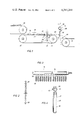
- FIG. 1 is a side elevation view showing the mechanical elements of the apparatus of the preferred embodiment of the invention.
- FIG. 2 is a view taken along line 2--2 of FIG. 1 showing the arrangement of the coils and magnet.
- FIG. 3 is a view taken along line 3--3 of FIG. 1 showing the air manifold and fingers.
- FIG. 4 is a partial sectional view of one finger.
- FIG. 5 is a block diagram showing the principal electronic components of the preferred embodiment of the present invention.
- FIG. 6 is a diagram of the clock and control logic circuit.
- FIG. 7 is a diagram of the duration discriminator circuit.
- the mechanical elements of the present invention include generally a first belt 11, a second belt 12, a clod detector 13, and clod rejecting means 14.
- First belt 11 is arranged for rotation about a pair of cylinders 20 and 21 in order to convey potatoes 16 and clods 17 in the direction of arrow 18 toward a forward end 22.
- Means (not shown) are provided for rotating cylinders 20 and 21 at a substantially constant speed. A substantially constant speed of rotation is desirable because of the horizontal spacing between clod detector 13 and clod rejecting means 14.
- Means which will be described in detail hereafter, are provided for delaying the actuation of clod rejecting means 14 after the clod that is to be rejected has been detected by clod detector 13. The length of the time delay is determined by the distance between detector 13 and rejecting means 14 and the speed of belt 11.
- a constant speed of rotation of cylinders 20 and 21 is also desirable in order to make more uniform the trajectories of potatoes and clods traveling between forward end 22 and belt 12.
- a constant speed of rotation is also desirable in order to make more uniform the frequency of signals generated by clods 17.
- Belt 11 should preferably be long enough to enable the clods and potatoes to become stable thereon, i.e., not bouncing or rolling, prior to reaching detector 13.
- the width of belt 11 should be sufficient to allow the potatoes and clods to be spread thereover in a monolayer, and not on top of each other.
- clods and potatoes are delivered to belt 11 by a third belt 30 that may or may not be driven at substantially the same speed as belt 11.
- Belt 30 may be driven electrically.
- Clod detector 13 includes a magnet 25 and a coil 26.
- magnet 25 is a bar magnet substantially as wide as belt 11 and polarized such that the upper surface thereof is of one pole and the lower surface is of the other. It will of course be recognized that magnet 25 may comprise a plurality of individual magnets. A permanent magnet is preferred over an electromagnet because it produces a uniform field that does not vary significantly with time.
- a plurality of coils 26 are spaced across the top of magnet 25. The diameter and spacing of coil 26 are determined by the size of the smallest clods to be encountered. Clods smaller than the smallest desired potatoes can be removed from the system prior to disposition on belt 11 by conventional grading apparatus.
- coil 26 When a clod 17 passes over coil 26, the strength of the magnetic field in the vicinity of coil 26 is affected, which causes a current to be induced in coil 26.
- the signal induced in coil 26 resembles one cycle of a sine wave, the amplitude thereof depending upon the size and the magnetic and conductive properties of the clod and the frequency thereof depending upon the speed of travel of belt 11.
- coil 26 and magnet 25 may be positioned on opposite sides of belt 11, as for example with magnet 25 positioned above belt 11 and coil 26 below.
- Clods are rejected by means of clod rejecting means 14, which includes an air manifold 35 that is connected to an air supply (not shown), and a plurality of normally flaccid inflatable fingers 36.
- Each finger 36 corresponds to and is associated with a coil 26 and the spacing of fingers 36 is substantially the same as the spacing of coils 26.
- each finger 36 includes an elastomeric sleeve 37 covered by a fabric sleeve 38.
- Fabric sleeve 38 is provided in order to keep elastomeric sleeve 37 from bulging and to make finger 36 more wear-resistant.
- the volume of finger 36 is preferably small in order to minimize the inflation and deflation time, and the quantity of air required.
- Air from air manifold 35 is connected to finger 36 by a solenoid-operated three-way valve 39.
- the electronics to be described hereafter, signal the valve 39 of the finger 36 corresponding to that coil 26 to open an airline 41 from air manifold 35 and admit air into finger 36.
- valve 39 is signaled to close airline 41 and open a vent port 40 and thereby vent finger 36 to the atmosphere.
- Potatoes leave forward end 22 and travel in the trajectory designated by the numeral 44. When a potato hits a flaccid finger 36, its trajectory 44 is not significantly affected and it lands on belt 12 and is conveyed away. However, when a clod hits a stiffened finger 36, its trajectory, designated by the numeral 45, is substantially deflected causing the clod to fall between forward end 22 and belt 12.
- amplifier 50 comprises a two-stage operational amplifier with associated components.
- the first stage of amplifier 50 is an inverting stage with a very low input impedance, and may consequently be considered to be a current-to-voltage converter.
- the second stage of amplifier 50 has a voltage gain adjustable over a range preferably from 100 to 500.
- the time constants of the feedback circuits and interstage and output coupling circuits are preferably selected to attenuate frequencies above and below the relatively narrow band occupied by legitimate clod signals.
- the output from amplifier 50 is input to an amplitude discriminator 51 that produces a logical true output when the output signal of amplifier 50 exceeds a preset level.
- Noise, potatoes, or clods of insignificant size produce signals that are too small to trigger the output of amplitude discriminator 51.
- delay 52 comprises a serial shift register that is clocked at 1 millisecond intervals by a clock signal. For example, if amplitude discriminator 51 output is true for 7.5 milliseconds, then a 7 millisecond pulse will be loaded into and moved down delay 52 at a rate of one step per millisecond. The number of steps in delay 52 is determined by the length of time necessary for a clod to travel from detector 13 to rejector 14.
- the required delay time is 120 milliseconds
- 120 steps are provided and a pulse loaded into such a delay will emerge 120 milliseconds later with its length preserved to the nearest millisecond.
- Several pulses may be in shift register delay 52 at any time and the delay time may be altered by changing the number of stages in the shift register or by changing the clock rate.
- the clock and control logic circuit designated generally by the numeral 55 is illustrated in detail in FIG. 6.
- one-Khz clock signal C is produced by dividing by two the output of two-Khz oscillator 54 with ripple counter 60.
- Clock signal C is used to load shift register delay 52 in the manner previously described.
- Clock and control logic circuit 55 also produces control signals P 1 and P 2 , which control duration discriminator 60.
- Duration discriminator 60 the circuitry of which is shown in FIG. 7, functions to reject any output from shift register delay 52 that is less than two clock cyles in duration, and to prevent recycling of valve 39 within a control deadtime interval, which is set by control one-shot 70. Duration discriminator 60 eliminates or reduces spurious behavior in the system.
- Control signal P 1 is produced by combining the outputs of oscillator 54 and ripple counter 60 through AND gate 56 and is true during the second quarter of the clock cycle.
- Control signal P 2 is produced by passing the output of ripple counter 60 through inverter 59 and combining the outputs of inverter 59 and oscillator 54 through AND gate 57.
- Control signal P 2 is true during the fourth quarter of the clock cycle. If the signal S from shift register delay 52 is true, then the output 61 of flip-flop 62 goes true when flip-flop 62 is clocked by control signal P 2 . Output 61 true means that S was true in the current clock cycle. If S stays true in the next clock cycle, a trigger pulse is supplied to valve one-shot 69 and control one-shot 70 through AND gate 63.
- the reset of flip-flop 62 occurs in two ways. Flip-flop 62 will be clocked to the reset state by P 2 if S is false, or it will be reset and held in that state by the output of AND gate 64. AND gate 64 couples the output 68 of control one-shot 70 to the reset input of flip-flop 62.
- control one-shot 70 input 65 to AND gate 64 via an inverter 66 delays the reset of flip-flop 62 until the end of the triger pulse of control one-shot 70, i.e. the end of P 1 .
- the forced reset inhibits retriggering for the duration of the control deadtime, which is substantially equal to the amount of time that a clod spends over a coil 26.
- control one-shot 70 If control one-shot 70 is triggered, it will produce a pulse of controlled preselected duration, which is the control deadtime.
- the leading edge of the output of control one-shot 70 triggers valve one-shot 69, which supplies a pulse of a preselected duration to valve driver 68.
- the output of control one-shot 70 also supplies an inhibit signal to duration discriminator 60.
- Valve driver 68 amplifies the signal from valve one-shot 69 and supplies current to operate solenoid valve 39. At the end of the signal produced by valve one-shot 69, the current to solenoid valve 39 is terminated and finger 36 again becomes flaccid.
- the mechanical elements of the apparatus are not as responsive and will not operate as quickly as the electronic elements. For example, the operation of valve 39 and the inflation and deflation of finger 36 will be delayed for some period of time after they are signaled to operate. However, the delay can be minimized by using a quick operating valve and by minimizing the volume of finger 36. Additionally, the mechanical delays can be determined and electronic delays can be designed accordingly.
- the apparatus of the present invention may be either incorporated in a potato harvesting machine or located in a warehouse or packing facility remote from the field.
- a supply of potatoes and clods are deposited upon belt 11 either by belt 30 or by some other means.
- the potatoes and clods are spread randomly across the width of belt 11 and moved at substantially constant speed toward forward end 22.
- Potatoes, which do not significantly affect the field of magnet 25, leave forward end 22 and travel along trajectory 44 to be received on belt 12.
- Clods in contrast, cause the field of magnet 25 to vary and induce a current in coil 26.
- the output from coil 26 is amplified by amplifier 50, which has a narrow pass band to attenuate frequencies outside the rather narrow range of frequencies expected for clods. If the output from amplifier 50 exceeds a certain amplitude, amplitude discriminator 51 supplies a pulse to shift register delay 52. Shift register delay 52 delays the stiffening of fingers 36 during the time needed for the clod to travel between detector 13 and rejector 14. The output of shift register delay 52 is received by duration discriminator 60, which eliminates signals of less than a certain preselected duration, which are considered to be spurious. The output of duration discriminator 60 is supplied to control one-shot 70, which actuates valve one-shot 69 and inhibits the reset of duration discriminator 60 during a preselected control deadtime.
- Valve one-shot 69 operates valve driver 68 which supplies current to solenoid valve 39.
- solenoid valve 39 opens, air from manifold 35 enters a finger 36 causing it to become stiff.
- the stiffness of finger 36 deflects downwardly the trajectory of a clod along the path 45, thereby causing the clod to miss belt 12.
Abstract
Description
Claims (7)
Priority Applications (1)
| Application Number | Priority Date | Filing Date | Title |
|---|---|---|---|
| US06/093,269 US4311241A (en) | 1979-11-13 | 1979-11-13 | Method for separating clods and the like from potatoes |
Applications Claiming Priority (1)
| Application Number | Priority Date | Filing Date | Title |
|---|---|---|---|
| US06/093,269 US4311241A (en) | 1979-11-13 | 1979-11-13 | Method for separating clods and the like from potatoes |
Publications (1)
| Publication Number | Publication Date |
|---|---|
| US4311241A true US4311241A (en) | 1982-01-19 |
Family
ID=22238039
Family Applications (1)
| Application Number | Title | Priority Date | Filing Date |
|---|---|---|---|
| US06/093,269 Expired - Lifetime US4311241A (en) | 1979-11-13 | 1979-11-13 | Method for separating clods and the like from potatoes |
Country Status (1)
| Country | Link |
|---|---|
| US (1) | US4311241A (en) |
Cited By (8)
| Publication number | Priority date | Publication date | Assignee | Title |
|---|---|---|---|---|
| US4466543A (en) * | 1980-10-02 | 1984-08-21 | Bystronic Maschinen Ag | Method and device for distinguishing between field crops, particularly potatoes on one hand and stones or clods of soil on the other hand |
| EP0353457A2 (en) * | 1988-08-05 | 1990-02-07 | S+S Metallsuchgeräte und Recyclingtechnik GmbH | Device for recognizing and separating impurities from a stream of synthetic or glass material |
| FR2649337A1 (en) * | 1989-07-06 | 1991-01-11 | Remex Sa | Sorting apparatus for separating at least two types of particles in a mixture of fragments |
| US5039534A (en) * | 1990-06-22 | 1991-08-13 | The Pillsbury Company | Pea separating apparatus and method of use |
| US20100213106A1 (en) * | 2007-10-19 | 2010-08-26 | Pal Srl | Apparatus for separating impurities in masses of incoherent materials and relative method |
| CN108940805A (en) * | 2018-08-08 | 2018-12-07 | 黑龙江八农垦大学 | A kind of potato full automatic grading cleaning and sorting system based on light spectrum image-forming |
| US11318476B2 (en) | 2020-04-30 | 2022-05-03 | Mss, Inc. | Separation of ferrous materials |
| US11465158B2 (en) | 2020-04-30 | 2022-10-11 | Mss, Inc. | Separation of ferrous materials |
Citations (6)
| Publication number | Priority date | Publication date | Assignee | Title |
|---|---|---|---|---|
| DE58411C (en) * | F. ROSE in Hamburg, Holsten-Platz Nr. 3 | Device for milling the free stud screw ends | ||
| US2228293A (en) * | 1938-03-14 | 1941-01-14 | Hugh E Wurzbach | Magnetic material detector |
| US2290930A (en) * | 1941-01-13 | 1942-07-28 | Hugh E Wurzbach | Magnetic material detector |
| US3268073A (en) * | 1960-02-16 | 1966-08-23 | Henry C Lehde | Separating apparatus |
| DE1914530A1 (en) * | 1968-03-26 | 1970-08-27 | Wilska Matti Gunnar | Sorting device for solid bodies |
| SU401408A2 (en) * | 1972-11-09 | 1973-10-12 |
-
1979
- 1979-11-13 US US06/093,269 patent/US4311241A/en not_active Expired - Lifetime
Patent Citations (6)
| Publication number | Priority date | Publication date | Assignee | Title |
|---|---|---|---|---|
| DE58411C (en) * | F. ROSE in Hamburg, Holsten-Platz Nr. 3 | Device for milling the free stud screw ends | ||
| US2228293A (en) * | 1938-03-14 | 1941-01-14 | Hugh E Wurzbach | Magnetic material detector |
| US2290930A (en) * | 1941-01-13 | 1942-07-28 | Hugh E Wurzbach | Magnetic material detector |
| US3268073A (en) * | 1960-02-16 | 1966-08-23 | Henry C Lehde | Separating apparatus |
| DE1914530A1 (en) * | 1968-03-26 | 1970-08-27 | Wilska Matti Gunnar | Sorting device for solid bodies |
| SU401408A2 (en) * | 1972-11-09 | 1973-10-12 |
Cited By (9)
| Publication number | Priority date | Publication date | Assignee | Title |
|---|---|---|---|---|
| US4466543A (en) * | 1980-10-02 | 1984-08-21 | Bystronic Maschinen Ag | Method and device for distinguishing between field crops, particularly potatoes on one hand and stones or clods of soil on the other hand |
| EP0353457A2 (en) * | 1988-08-05 | 1990-02-07 | S+S Metallsuchgeräte und Recyclingtechnik GmbH | Device for recognizing and separating impurities from a stream of synthetic or glass material |
| EP0353457A3 (en) * | 1988-08-05 | 1990-04-18 | S + S Elektronik Geratebau Gmbh | Device for recognizing and separating impurities from a stream of synthetic or glass material |
| FR2649337A1 (en) * | 1989-07-06 | 1991-01-11 | Remex Sa | Sorting apparatus for separating at least two types of particles in a mixture of fragments |
| US5039534A (en) * | 1990-06-22 | 1991-08-13 | The Pillsbury Company | Pea separating apparatus and method of use |
| US20100213106A1 (en) * | 2007-10-19 | 2010-08-26 | Pal Srl | Apparatus for separating impurities in masses of incoherent materials and relative method |
| CN108940805A (en) * | 2018-08-08 | 2018-12-07 | 黑龙江八农垦大学 | A kind of potato full automatic grading cleaning and sorting system based on light spectrum image-forming |
| US11318476B2 (en) | 2020-04-30 | 2022-05-03 | Mss, Inc. | Separation of ferrous materials |
| US11465158B2 (en) | 2020-04-30 | 2022-10-11 | Mss, Inc. | Separation of ferrous materials |
Similar Documents
| Publication | Publication Date | Title |
|---|---|---|
| US4311241A (en) | Method for separating clods and the like from potatoes | |
| US3701419A (en) | Method of and apparatus for sorting ores | |
| US3435950A (en) | Materials separation devices | |
| US2587686A (en) | Ore sorting system | |
| US3476241A (en) | System for the selective stacking of sheet material | |
| US2176784A (en) | Method of and apparatus for grading magnetic sheet material | |
| EP0049681B1 (en) | Method and device for distinguishing between ground fruits on the one hand and stones and clods on the other hand | |
| US2470889A (en) | Method and apparatus for separating magnetic from nonmagnetic materials | |
| EP0541403A2 (en) | Aluminum recovery system | |
| US4375853A (en) | Apparatus for separating clods and agricultural products | |
| US4164291A (en) | Sorting apparatus | |
| JP3221828U (en) | Magnetic force sorting apparatus and foreign matter sorting system | |
| EP1576550B1 (en) | Method and device for sorting, counting and/or inspecting objects | |
| US4738367A (en) | Magnetic refuse separator | |
| US3706027A (en) | Materials counting system utilizing permanent magnets and their associated fields | |
| GB1407481A (en) | Ore separation | |
| US3268073A (en) | Separating apparatus | |
| JPS584392A (en) | Device for treating potato | |
| WO1991006928A1 (en) | Sorting mechanism for coins | |
| EP1347311B1 (en) | Method for detecting objects, particularly metal objects | |
| JPS6210257Y2 (en) | ||
| US3259225A (en) | Marshalling apparatus | |
| US2654478A (en) | Method and apparatus for automatically separating underweight cans from normal weight cans | |
| WO1992001617A1 (en) | Magnetic trap assembly | |
| DE1125740B (en) | Method and device for separating vegetable tubers, stones and clods |
Legal Events
| Date | Code | Title | Description |
|---|---|---|---|
| STCF | Information on status: patent grant |
Free format text: PATENTED CASE |
|
| AS | Assignment |
Owner name: WASHINGTON SQUARE CAPITAL, INC., A CORP. OF MN, MI Free format text: SECURITY INTEREST;ASSIGNOR:LOCKWOOD CORPORATION;REEL/FRAME:005333/0519 Effective date: 19891116 |
|
| AS | Assignment |
Owner name: LOCKWOOD CORPORATION, NEBRASKA Free format text: RELEASE BY SECURED PARTY;ASSIGNOR:WASHINGTON SQUARE CAPITAL, INC.;REEL/FRAME:006891/0376 Effective date: 19940204 |
|
| AS | Assignment |
Owner name: NORWEST BANK MINNESOTA, NATIONAL ASSOCIATION, MINN Free format text: ASSIGNMENT OF ASSIGNORS INTEREST;ASSIGNOR:LOCKWOOD CORPORATION;REEL/FRAME:007764/0490 Effective date: 19940131 |
|
| AS | Assignment |
Owner name: NORWEST BANK MINNESOTA, NATIONAL ASSOCIATION, MINN Free format text: ASSIGNMENT OF ASSIGNORS INTEREST;ASSIGNOR:LOCKWOOD CORPORATION;REEL/FRAME:007779/0414 Effective date: 19940131 |
|
| AS | Assignment |
Owner name: NORWEST BANK MINNESOTA, NATIONAL ASSOCIATION, MINN Free format text: ASSIGNMENT OF ASSIGNORS INTEREST;ASSIGNOR:LOCKWOOD CORPORATION;REEL/FRAME:007773/0688 Effective date: 19960111 |
|
| AS | Assignment |
Owner name: AGROMAC INTERNATIONAL INC., NEBRASKA Free format text: ASSIGNMENT OF ASSIGNORS INTEREST;ASSIGNOR:NORWEST BANK MINNESOTA;REEL/FRAME:007795/0211 Effective date: 19960125 |
|
| AS | Assignment |
Owner name: NORWEST BANK MINNESOTA, NATIONAL ASSOCIATION, MIN Free format text: ASSIGNMENT OF ASSIGNORS INTEREST;ASSIGNOR:AGROMAC INTERNATIONAL, INC.;REEL/FRAME:007824/0232 Effective date: 19960213 |
|
| AS | Assignment |
Owner name: LASALLE NATIONAL BANK, ILLINOIS Free format text: SECURITY INTEREST;ASSIGNORS:AGRI-HOLDINGS INTERNATIONAL, INC. D/B/A SPECIALTY AGRICULTURAL PRODUCTS;HARRISTON INDUSTRIES, INC.;LOCKWOOD MANUFACTURING, INC.;AND OTHERS;REEL/FRAME:009773/0695 Effective date: 19990205 |