US4296979A - Journal bearing for the shaft of a water pump or the like - Google Patents
Journal bearing for the shaft of a water pump or the like Download PDFInfo
- Publication number
- US4296979A US4296979A US06/123,027 US12302780A US4296979A US 4296979 A US4296979 A US 4296979A US 12302780 A US12302780 A US 12302780A US 4296979 A US4296979 A US 4296979A
- Authority
- US
- United States
- Prior art keywords
- sleeve
- shaft
- balls
- sets
- rollers
- Prior art date
- Legal status (The legal status is an assumption and is not a legal conclusion. Google has not performed a legal analysis and makes no representation as to the accuracy of the status listed.)
- Expired - Lifetime
Links
Images
Classifications
-
- F—MECHANICAL ENGINEERING; LIGHTING; HEATING; WEAPONS; BLASTING
- F04—POSITIVE - DISPLACEMENT MACHINES FOR LIQUIDS; PUMPS FOR LIQUIDS OR ELASTIC FLUIDS
- F04D—NON-POSITIVE-DISPLACEMENT PUMPS
- F04D29/00—Details, component parts, or accessories
- F04D29/04—Shafts or bearings, or assemblies thereof
- F04D29/046—Bearings
- F04D29/049—Roller bearings
-
- F—MECHANICAL ENGINEERING; LIGHTING; HEATING; WEAPONS; BLASTING
- F04—POSITIVE - DISPLACEMENT MACHINES FOR LIQUIDS; PUMPS FOR LIQUIDS OR ELASTIC FLUIDS
- F04D—NON-POSITIVE-DISPLACEMENT PUMPS
- F04D29/00—Details, component parts, or accessories
- F04D29/04—Shafts or bearings, or assemblies thereof
- F04D29/046—Bearings
- F04D29/0462—Bearing cartridges
-
- F—MECHANICAL ENGINEERING; LIGHTING; HEATING; WEAPONS; BLASTING
- F16—ENGINEERING ELEMENTS AND UNITS; GENERAL MEASURES FOR PRODUCING AND MAINTAINING EFFECTIVE FUNCTIONING OF MACHINES OR INSTALLATIONS; THERMAL INSULATION IN GENERAL
- F16C—SHAFTS; FLEXIBLE SHAFTS; ELEMENTS OR CRANKSHAFT MECHANISMS; ROTARY BODIES OTHER THAN GEARING ELEMENTS; BEARINGS
- F16C19/00—Bearings with rolling contact, for exclusively rotary movement
- F16C19/49—Bearings with both balls and rollers
-
- F—MECHANICAL ENGINEERING; LIGHTING; HEATING; WEAPONS; BLASTING
- F16—ENGINEERING ELEMENTS AND UNITS; GENERAL MEASURES FOR PRODUCING AND MAINTAINING EFFECTIVE FUNCTIONING OF MACHINES OR INSTALLATIONS; THERMAL INSULATION IN GENERAL
- F16C—SHAFTS; FLEXIBLE SHAFTS; ELEMENTS OR CRANKSHAFT MECHANISMS; ROTARY BODIES OTHER THAN GEARING ELEMENTS; BEARINGS
- F16C33/00—Parts of bearings; Special methods for making bearings or parts thereof
- F16C33/30—Parts of ball or roller bearings
- F16C33/38—Ball cages
-
- F—MECHANICAL ENGINEERING; LIGHTING; HEATING; WEAPONS; BLASTING
- F16—ENGINEERING ELEMENTS AND UNITS; GENERAL MEASURES FOR PRODUCING AND MAINTAINING EFFECTIVE FUNCTIONING OF MACHINES OR INSTALLATIONS; THERMAL INSULATION IN GENERAL
- F16C—SHAFTS; FLEXIBLE SHAFTS; ELEMENTS OR CRANKSHAFT MECHANISMS; ROTARY BODIES OTHER THAN GEARING ELEMENTS; BEARINGS
- F16C33/00—Parts of bearings; Special methods for making bearings or parts thereof
- F16C33/30—Parts of ball or roller bearings
- F16C33/46—Cages for rollers or needles
- F16C33/4605—Details of interaction of cage and race, e.g. retention or centring
-
- F—MECHANICAL ENGINEERING; LIGHTING; HEATING; WEAPONS; BLASTING
- F16—ENGINEERING ELEMENTS AND UNITS; GENERAL MEASURES FOR PRODUCING AND MAINTAINING EFFECTIVE FUNCTIONING OF MACHINES OR INSTALLATIONS; THERMAL INSULATION IN GENERAL
- F16C—SHAFTS; FLEXIBLE SHAFTS; ELEMENTS OR CRANKSHAFT MECHANISMS; ROTARY BODIES OTHER THAN GEARING ELEMENTS; BEARINGS
- F16C33/00—Parts of bearings; Special methods for making bearings or parts thereof
- F16C33/30—Parts of ball or roller bearings
- F16C33/46—Cages for rollers or needles
- F16C33/4617—Massive or moulded cages having cage pockets surrounding the rollers, e.g. machined window cages
- F16C33/4623—Massive or moulded cages having cage pockets surrounding the rollers, e.g. machined window cages formed as one-piece cages, i.e. monoblock cages
-
- F—MECHANICAL ENGINEERING; LIGHTING; HEATING; WEAPONS; BLASTING
- F16—ENGINEERING ELEMENTS AND UNITS; GENERAL MEASURES FOR PRODUCING AND MAINTAINING EFFECTIVE FUNCTIONING OF MACHINES OR INSTALLATIONS; THERMAL INSULATION IN GENERAL
- F16C—SHAFTS; FLEXIBLE SHAFTS; ELEMENTS OR CRANKSHAFT MECHANISMS; ROTARY BODIES OTHER THAN GEARING ELEMENTS; BEARINGS
- F16C33/00—Parts of bearings; Special methods for making bearings or parts thereof
- F16C33/30—Parts of ball or roller bearings
- F16C33/46—Cages for rollers or needles
- F16C33/49—Cages for rollers or needles comb-shaped
- F16C33/494—Massive or moulded comb cages
- F16C33/495—Massive or moulded comb cages formed as one piece cages, i.e. monoblock comb cages
-
- F—MECHANICAL ENGINEERING; LIGHTING; HEATING; WEAPONS; BLASTING
- F16—ENGINEERING ELEMENTS AND UNITS; GENERAL MEASURES FOR PRODUCING AND MAINTAINING EFFECTIVE FUNCTIONING OF MACHINES OR INSTALLATIONS; THERMAL INSULATION IN GENERAL
- F16C—SHAFTS; FLEXIBLE SHAFTS; ELEMENTS OR CRANKSHAFT MECHANISMS; ROTARY BODIES OTHER THAN GEARING ELEMENTS; BEARINGS
- F16C2360/00—Engines or pumps
- F16C2360/44—Centrifugal pumps
Definitions
- Our present invention relates to an assembly of a rotatable shaft, e.g. that of a water pump for an automotive vehicle or the like, and a journal bearing therefor also designed to hold that shaft against axial displacement.
- the shaft of a vehicular water pump for example, is subjected to torques due to unbalances of the pump motor and other components carried thereon, e.g. a fan, aside from experiencing bending moments due to the stress of the V-belt by which it is driven.
- the mounting of that shaft therefore, must be designed to absorb all these stresses while also resisting axial forces, e.g. those resulting from the air pressure upon the fan blades.
- a set of centrally disposed bearing balls or rollers contributes nothing to the absorption of bending moments such as those exerted by a driving belt. Rollers, which tend to stiffen the shaft against radial deflection, are therefore more advantageously placed near an end of a journal bearing as described in the commonly owned application referred to.
- a third set of rotary bodies increases the load-sustaining capacity of the bearing, especially when the surrounding cylinder is of unitary all-metallic structure.
- Balls guided in track grooves are conventionally used to prevent relative axial shifts of the two races. As long as the combined depth of the two confronting grooves is substantially less than the ball radius, the balls can be readily inserted when the sleeve is eccentrically positioned on the shaft, this operation being followed by a peripheral distribution of the balls in the clearance between the shaft and the sleeve while the latter is being centered on the shaft axis.
- the balls can then be held separated by an axially introduced annular cage as is well known per se. Only two axially spaced sets of balls, however, can be introduced into a unitary bearing sleeve by this procedure.
- the object of our present invention is to provide a bearing assembly with three sets of rotary bodies designed to resist axial and radial stresses as well as bending moments.
- a set of rollers are inserted in the second zone between the shaft and the sleeve, these rollers being engaged by a third cage which has a peripheral rib snap-fitted into the retaining groove of the sleeve.
- the roller as well as the balls are preferably in direct contact with the shaft surface though the interposition of a bushing (suitably grooved in the case of the balls) is by no means excluded.
- the two sets of balls should lie on one side of the axial midpoint of the sleeve, with the rollers located on the opposite side thereof.
- the shaft is stiffened to resist bending at both ends of the bearing sleeve.
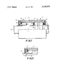
- FIG. 1 shows, in elevation and partly in axial section, a bearing assembly for a rotatable shaft embodying our invention
- FIG. 2 is a fragmentary part-sectional view illustrating a modification.
- FIG. 1 we have shown a horizontal shaft 1, which may be that of a vehicular water pump, mounted in a nonillustrated housing through the intermediary of a bearing sleeve 5 centered on the shaft axis 0.
- the cylindrical inner surface of the unitary metallic sleeve 5 is formed with two shallow track grooves 10 and 11 of arcuate cross-section confronting similar grooves 12 and 13 on the shaft surface.
- Two sets of balls 2 and 3 are respectively received in the groove pairs 10, 12, and 11, 13, the balls of each set being held spaced apart by an annular cage 6' or 6" of crenellate configuration resiliently engaging the balls over roughly 270° of their periphery.
- a retaining groove 14 of triangular cross-section receiving a peripheral rib 7a of an annular cage 7 with pockets fully embracing respective rollers 4.
- the annular space accommodating the rotary bodies 2, 3 and 4 is closed against the outside by flexible sealing rings 8 snapped into peripheral grooves 15, e.g. as known per se from commonly owned U.S. Pat. No. 3,796,510.
- cage 7 and rollers 4 can be preassembled on the projecting left-hand extremity of shaft 1 and then slid axially into the sleeve 5 after the balls 2, 3 and their cages 6', 6" have been emplaced near its right-hand end in the manner described above.
- cage 7 may be replaced by a crenellated cage 7' with open-ended pockets partly embracing the rollers 4, the sleeve 5' being provided in that case with an internal annular shoulder 9 to prevent a rightward shift of the rollers. It will be apparent that, instead or in addition, such a shoulder could also be formed on the shaft 1.
- rollers 4 The axial separation of rollers 4 from the nearer set of balls 3 substantially exceeds the mutual axial spacing of the two sets of balls 2 and 3.
Landscapes
- Engineering & Computer Science (AREA)
- General Engineering & Computer Science (AREA)
- Mechanical Engineering (AREA)
- Rolling Contact Bearings (AREA)
Abstract
A journal bearing for a pump shaft comprises a sleeve whose inner peripheral surface forms two grooved tracks for respective sets of bearing balls adjacent one end thereof and forms a retaining groove near the other end. The two sets of bearing balls, held in respective cages, are also received in a pair of closely spaced peripheral grooves of the shaft confronting the tracks of the sleeve, thereby preventing relative axial shifting of the sleeve and the shaft. A set of bearing rollers are inserted between smooth surface portions of the shaft and the sleeve near the opposite end of the latter and are lodged in pockets of an annular cage having a peripheral rib snap-fitted into the retaining groove.
Description
Our present invention relates to an assembly of a rotatable shaft, e.g. that of a water pump for an automotive vehicle or the like, and a journal bearing therefor also designed to hold that shaft against axial displacement.
For the absorption of both radial and axial stresses it is known to use one or more sets of rotary bodies, i.e. rollers or balls, which are partly received in confronting track grooves of an outer race formed by a bearing sleeve and an inner race which may be constituted by the peripheral surface of the shaft itself.
The shaft of a vehicular water pump, for example, is subjected to torques due to unbalances of the pump motor and other components carried thereon, e.g. a fan, aside from experiencing bending moments due to the stress of the V-belt by which it is driven. The mounting of that shaft, therefore, must be designed to absorb all these stresses while also resisting axial forces, e.g. those resulting from the air pressure upon the fan blades.
In a commonly owned copending application, Ser. No. 76,360 filed 17 Sept. 1979 by Roland Tischer, now U.S. Pat. No. 4,244,630, there has been disclosed a bearing assembly with two sets of rotary bodies, specifically a set of balls and a set of rollers, near opposite ends of a cylindrical shell coaxially surrounding the associated shaft. In order to facilitate the assembly of such a shaft mounting, the shell is divided into two axially spaced bearing rings interconnected by a sleeve of elastomeric material engaging these rings with a snap fit. A bearing with three sets of rotary bodies, namely two outer rows of balls and a centrally disposed row of rollers, is disclosed in Swiss Pat. No. 165,580.
In general, a set of centrally disposed bearing balls or rollers contributes nothing to the absorption of bending moments such as those exerted by a driving belt. Rollers, which tend to stiffen the shaft against radial deflection, are therefore more advantageously placed near an end of a journal bearing as described in the commonly owned application referred to.
Still, the provision of a third set of rotary bodies increases the load-sustaining capacity of the bearing, especially when the surrounding cylinder is of unitary all-metallic structure. Balls guided in track grooves are conventionally used to prevent relative axial shifts of the two races. As long as the combined depth of the two confronting grooves is substantially less than the ball radius, the balls can be readily inserted when the sleeve is eccentrically positioned on the shaft, this operation being followed by a peripheral distribution of the balls in the clearance between the shaft and the sleeve while the latter is being centered on the shaft axis. The balls can then be held separated by an axially introduced annular cage as is well known per se. Only two axially spaced sets of balls, however, can be introduced into a unitary bearing sleeve by this procedure.
The object of our present invention is to provide a bearing assembly with three sets of rotary bodies designed to resist axial and radial stresses as well as bending moments.
We realize this object, in accordance with our present invention, by the provision of a sleeve whose inner peripheral surface has a first zone with two closely spaced annular track grooves adjacent one end thereof and a second zone with an annular retaining groove adjacent the other end thereof, the associated shaft being provided with two closely spaced peripheral track grooves respectively confronting the annular track grooves of the first zone of the sleeve. The balls of the two sets are engaged by respective cages which, in order to be insertable into the sleeve from opposite ends, should have ball-receiving pockets that are open toward each other. A set of rollers are inserted in the second zone between the shaft and the sleeve, these rollers being engaged by a third cage which has a peripheral rib snap-fitted into the retaining groove of the sleeve. The roller as well as the balls are preferably in direct contact with the shaft surface though the interposition of a bushing (suitably grooved in the case of the balls) is by no means excluded.
For optimum absorption of bending moments, the two sets of balls should lie on one side of the axial midpoint of the sleeve, with the rollers located on the opposite side thereof. Thus, the shaft is stiffened to resist bending at both ends of the bearing sleeve.
The above and other features of our invention will now be described in detail with reference to the accompanying drawing in which:
FIG. 1 shows, in elevation and partly in axial section, a bearing assembly for a rotatable shaft embodying our invention; and
FIG. 2 is a fragmentary part-sectional view illustrating a modification.
In FIG. 1 we have shown a horizontal shaft 1, which may be that of a vehicular water pump, mounted in a nonillustrated housing through the intermediary of a bearing sleeve 5 centered on the shaft axis 0. The cylindrical inner surface of the unitary metallic sleeve 5 is formed with two shallow track grooves 10 and 11 of arcuate cross-section confronting similar grooves 12 and 13 on the shaft surface. Two sets of balls 2 and 3 are respectively received in the groove pairs 10, 12, and 11, 13, the balls of each set being held spaced apart by an annular cage 6' or 6" of crenellate configuration resiliently engaging the balls over roughly 270° of their periphery. At the opposite end of sleeve 5 there is provided a retaining groove 14 of triangular cross-section receiving a peripheral rib 7a of an annular cage 7 with pockets fully embracing respective rollers 4. The annular space accommodating the rotary bodies 2, 3 and 4 is closed against the outside by flexible sealing rings 8 snapped into peripheral grooves 15, e.g. as known per se from commonly owned U.S. Pat. No. 3,796,510.
The combination of cage 7 and rollers 4 can be preassembled on the projecting left-hand extremity of shaft 1 and then slid axially into the sleeve 5 after the balls 2, 3 and their cages 6', 6" have been emplaced near its right-hand end in the manner described above.
As shown in FIG. 2, cage 7 may be replaced by a crenellated cage 7' with open-ended pockets partly embracing the rollers 4, the sleeve 5' being provided in that case with an internal annular shoulder 9 to prevent a rightward shift of the rollers. It will be apparent that, instead or in addition, such a shoulder could also be formed on the shaft 1.
The axial separation of rollers 4 from the nearer set of balls 3 substantially exceeds the mutual axial spacing of the two sets of balls 2 and 3.
Claims (4)
1. In an assembly of a rotatable shaft and a journal bearing therefor,
the improvement wherein said journal bearing comprises: a sleeve with a cylindrical inner peripheral surface having a first zone with two closely spaced annular track grooves offset from the axial midpoint of the sleeve adjacent one end thereof and a second zone with an annular retaining groove adjacent the other end thereof, said shaft being provided with two closely spaced peripheral track grooves respectively confronting the annular track grooves of said first zone;
two sets of balls respectively received in said track grooves of said shaft and said sleeve, the balls of each set being respectively engaged by a first and a second cage;
a set of rollers inserted in said second zone between said shaft and said sleeve; and
a third cage engaging said rollers, said third cage being provided with a peripheral rib snap-fitted into said retaining groove.
2. An assembly as defined in claim 1 wherein said rollers are separated from said sets of balls by an axial distance substantially exceeding the axial spacing of said sets of balls from each other.
3. An assembly as defined in claim 1 or 2 wherein said first and second cages have ball-receiving pockets open toward each other.
4. An assembly as defined in claim 1 or 2 wherein said sleeve is a unitary metallic member.
Applications Claiming Priority (2)
| Application Number | Priority Date | Filing Date | Title |
|---|---|---|---|
| DE19792907342 DE2907342A1 (en) | 1979-02-24 | 1979-02-24 | RADIAL-AXIAL BEARING |
| DE2907342 | 1979-02-24 |
Publications (1)
| Publication Number | Publication Date |
|---|---|
| US4296979A true US4296979A (en) | 1981-10-27 |
Family
ID=6063880
Family Applications (1)
| Application Number | Title | Priority Date | Filing Date |
|---|---|---|---|
| US06/123,027 Expired - Lifetime US4296979A (en) | 1979-02-24 | 1980-02-20 | Journal bearing for the shaft of a water pump or the like |
Country Status (2)
| Country | Link |
|---|---|
| US (1) | US4296979A (en) |
| DE (1) | DE2907342A1 (en) |
Cited By (11)
| Publication number | Priority date | Publication date | Assignee | Title |
|---|---|---|---|---|
| US4398775A (en) * | 1980-07-19 | 1983-08-16 | Fag Kugelfischer Georg Schafer & Co. | Journal bearing with one axially divided inner or outer ring |
| US4509871A (en) * | 1982-11-30 | 1985-04-09 | Carl-Zeiss-Stiftung, Heidenheim/Brenz | Play-free anti-friction bearing construction |
| US4541786A (en) * | 1982-09-03 | 1985-09-17 | Ford Motor Company | Ceramic turbocharger |
| US5482150A (en) * | 1992-03-31 | 1996-01-09 | Ina Walzlager Schaeffler Kg | Bushed overrunning clutches |
| DE19646338A1 (en) * | 1996-11-09 | 1998-05-14 | Schaeffler Waelzlager Ohg | Axial roller bearing comprising cage containing roller body |
| US20040168534A1 (en) * | 2001-07-26 | 2004-09-02 | Manfred Winkler | Idler bearing |
| US20100027931A1 (en) * | 2007-03-09 | 2010-02-04 | Cislo Lawrence | Wheel end support bearing |
| US20160061258A1 (en) * | 2014-08-28 | 2016-03-03 | Schaeffler Technologies AG & Co. KG | Needle bearing with a cage and a retaining tab formed on the cage |
| US20160076590A1 (en) * | 2015-11-24 | 2016-03-17 | Schaeffler Technologies AG & Co. KG | Ball bearing with slanted or angled flat raceways |
| US10527097B2 (en) * | 2017-03-07 | 2020-01-07 | Aktiebolaget Skf | Roller bearing and a mechanical system comprising such a roller bearing |
| US11274699B2 (en) | 2019-11-05 | 2022-03-15 | Roller Bearing Company Of America, Inc. | Double row needle track roller bearing with a thrust load carrying ball bearing |
Families Citing this family (4)
| Publication number | Priority date | Publication date | Assignee | Title |
|---|---|---|---|---|
| GB2183742B (en) * | 1985-10-25 | 1990-07-11 | Csu Ltd | Spindle unit |
| RU2216659C2 (en) * | 2001-10-19 | 2003-11-20 | Кузнецов Петр Владимирович | Bearing unit |
| DE102005014919A1 (en) * | 2005-04-01 | 2006-10-12 | Schaeffler Kg | Unit for use with water pump for internal combustion engine coolant circuit, has bearing with two rows rolling units, where each row is assigned to outer track of bearing formed directly in material of housing |
| DE102007013940A1 (en) | 2007-03-23 | 2008-09-25 | Schaeffler Kg | Roller bearing arrangement for a shaft as a main spindle for processing tools comprises a radial bearing having a divided cylinder roll bearing formed so that a rolling body cage with rolling bodies can be sorted after assembly |
Citations (8)
| Publication number | Priority date | Publication date | Assignee | Title |
|---|---|---|---|---|
| CH165580A (en) * | 1932-09-21 | 1933-11-30 | Kallai Joseph | Roller bearing. |
| US3416848A (en) * | 1966-08-10 | 1968-12-17 | Fed Bearing Co Inc | Combination ball and needle bearing with minimum rolling friction |
| US3424507A (en) * | 1966-08-02 | 1969-01-28 | Torrington Co | Water pump bearing |
| US3899225A (en) * | 1972-12-01 | 1975-08-12 | Torrington Co | Radial and thrust bearing |
| GB1406982A (en) * | 1972-10-23 | 1975-09-24 | Skf Uk Ltd | Spindle and bearing assemblies |
| US3973811A (en) * | 1974-01-14 | 1976-08-10 | John Michael Noguera | Ball bearing rollers for ring spinning machines |
| US4153309A (en) * | 1976-10-28 | 1979-05-08 | Kugelfischer Georg Schafer & Co. | Shoulderless roller bearing |
| US4244630A (en) * | 1978-09-19 | 1981-01-13 | Fag Kugelfischer Georg Schafer & Co. | Journal mounting for the shaft of a water pump or the like |
-
1979
- 1979-02-24 DE DE19792907342 patent/DE2907342A1/en not_active Ceased
-
1980
- 1980-02-20 US US06/123,027 patent/US4296979A/en not_active Expired - Lifetime
Patent Citations (8)
| Publication number | Priority date | Publication date | Assignee | Title |
|---|---|---|---|---|
| CH165580A (en) * | 1932-09-21 | 1933-11-30 | Kallai Joseph | Roller bearing. |
| US3424507A (en) * | 1966-08-02 | 1969-01-28 | Torrington Co | Water pump bearing |
| US3416848A (en) * | 1966-08-10 | 1968-12-17 | Fed Bearing Co Inc | Combination ball and needle bearing with minimum rolling friction |
| GB1406982A (en) * | 1972-10-23 | 1975-09-24 | Skf Uk Ltd | Spindle and bearing assemblies |
| US3899225A (en) * | 1972-12-01 | 1975-08-12 | Torrington Co | Radial and thrust bearing |
| US3973811A (en) * | 1974-01-14 | 1976-08-10 | John Michael Noguera | Ball bearing rollers for ring spinning machines |
| US4153309A (en) * | 1976-10-28 | 1979-05-08 | Kugelfischer Georg Schafer & Co. | Shoulderless roller bearing |
| US4244630A (en) * | 1978-09-19 | 1981-01-13 | Fag Kugelfischer Georg Schafer & Co. | Journal mounting for the shaft of a water pump or the like |
Cited By (14)
| Publication number | Priority date | Publication date | Assignee | Title |
|---|---|---|---|---|
| US4398775A (en) * | 1980-07-19 | 1983-08-16 | Fag Kugelfischer Georg Schafer & Co. | Journal bearing with one axially divided inner or outer ring |
| US4541786A (en) * | 1982-09-03 | 1985-09-17 | Ford Motor Company | Ceramic turbocharger |
| US4509871A (en) * | 1982-11-30 | 1985-04-09 | Carl-Zeiss-Stiftung, Heidenheim/Brenz | Play-free anti-friction bearing construction |
| US5482150A (en) * | 1992-03-31 | 1996-01-09 | Ina Walzlager Schaeffler Kg | Bushed overrunning clutches |
| DE19646338B4 (en) * | 1996-11-09 | 2005-06-09 | Ina-Schaeffler Kg | thrust roller bearing |
| DE19646338A1 (en) * | 1996-11-09 | 1998-05-14 | Schaeffler Waelzlager Ohg | Axial roller bearing comprising cage containing roller body |
| US5879086A (en) * | 1996-11-09 | 1999-03-09 | Ina Walzlager Schaeffler Kg | Axial rolling bearing |
| US20040168534A1 (en) * | 2001-07-26 | 2004-09-02 | Manfred Winkler | Idler bearing |
| US20100027931A1 (en) * | 2007-03-09 | 2010-02-04 | Cislo Lawrence | Wheel end support bearing |
| US8753018B2 (en) | 2007-03-09 | 2014-06-17 | Schaeffler Kg | Wheel end support bearing |
| US20160061258A1 (en) * | 2014-08-28 | 2016-03-03 | Schaeffler Technologies AG & Co. KG | Needle bearing with a cage and a retaining tab formed on the cage |
| US20160076590A1 (en) * | 2015-11-24 | 2016-03-17 | Schaeffler Technologies AG & Co. KG | Ball bearing with slanted or angled flat raceways |
| US10527097B2 (en) * | 2017-03-07 | 2020-01-07 | Aktiebolaget Skf | Roller bearing and a mechanical system comprising such a roller bearing |
| US11274699B2 (en) | 2019-11-05 | 2022-03-15 | Roller Bearing Company Of America, Inc. | Double row needle track roller bearing with a thrust load carrying ball bearing |
Also Published As
| Publication number | Publication date |
|---|---|
| DE2907342A1 (en) | 1980-09-04 |
Similar Documents
| Publication | Publication Date | Title |
|---|---|---|
| US4296979A (en) | Journal bearing for the shaft of a water pump or the like | |
| US6957919B2 (en) | Double-row angular contact ball bearing | |
| US5009525A (en) | Roller seating | |
| US4129343A (en) | Unitary self-aligning bearing assembly | |
| US4475777A (en) | Split-ring roller bearing | |
| US4324444A (en) | Snap-in bearing retainer and bearing | |
| US6273614B1 (en) | Rolling and bearing comprising a temperature compensating insert | |
| EP0656484B1 (en) | Roller guide member for roller bearing | |
| US20040076355A1 (en) | Single row deep groove radial ball bearing | |
| US4472006A (en) | Roller bearing with an improved cage | |
| US4886479A (en) | Universal joint including roller bearings | |
| KR20060037353A (en) | Wheel bearing unit embodied as an angular contact ball bearing | |
| JPH0617824A (en) | Sealed four-row taper-roller bearing | |
| US20020147052A1 (en) | Flexible boot assembly for a constant velocity joint | |
| AU607936B2 (en) | Molded rubber seal for bearing and stamping assembly | |
| US6913540B2 (en) | Constant velocity universal joint for propeller shaft | |
| US4244630A (en) | Journal mounting for the shaft of a water pump or the like | |
| US4729670A (en) | Roller bearing | |
| US5232289A (en) | Stud type track roller bearing | |
| SE466140B (en) | DOUBLE ROLLING STOCK, SPECIFICALLY DRIVING VEHICLE WHEELS | |
| US4432741A (en) | Joint means for transmitting a moment of rotation in both directions | |
| CA1244074A (en) | Double row cylindrical expansion bearing | |
| EP0031188B1 (en) | Homokinetic coupling | |
| US4830516A (en) | Roller bearing | |
| WO2001025647A1 (en) | Cylindrical bearing having a two-piece cage configuration with a dual gothic arch pocket geometry |
Legal Events
| Date | Code | Title | Description |
|---|---|---|---|
| STCF | Information on status: patent grant |
Free format text: PATENTED CASE |
|
| AS | Assignment |
Owner name: FAG KUGELFISCHER GEORG SCHAFER KOMMANDITGESELLSCHA Free format text: CHANGE OF NAME;ASSIGNOR:FAG KUGELFISCHER GEORG SCHAFER & CO.;REEL/FRAME:004182/0129 Effective date: 19830826 |