US429552A - Advertising-clock - Google Patents
Advertising-clock Download PDFInfo
- Publication number
- US429552A US429552A US429552DA US429552A US 429552 A US429552 A US 429552A US 429552D A US429552D A US 429552DA US 429552 A US429552 A US 429552A
- Authority
- US
- United States
- Prior art keywords
- shafts
- rock
- sheet
- advertising
- clock
- Prior art date
- Legal status (The legal status is an assumption and is not a legal conclusion. Google has not performed a legal analysis and makes no representation as to the accuracy of the status listed.)
- Expired - Lifetime
Links
Images


Classifications
-
- G—PHYSICS
- G09—EDUCATION; CRYPTOGRAPHY; DISPLAY; ADVERTISING; SEALS
- G09F—DISPLAYING; ADVERTISING; SIGNS; LABELS OR NAME-PLATES; SEALS
- G09F11/00—Indicating arrangements for variable information in which the complete information is permanently attached to a movable support which brings it to the display position
- G09F11/23—Indicating arrangements for variable information in which the complete information is permanently attached to a movable support which brings it to the display position the advertising or display material forming part of rotating members, e.g. in the form of perforations, prints, or transparencies on a drum or disc
Definitions
- My invention relates to certain novel and useful improvements in machines for displaying advertisements, and which are preferably incased with a clock or music-box for the purpose of attracting attention-such, for instance, as shown in patent to Woolverton, No. 392,939, November 13, 1888; and the objects of my invention are to furnish a simple and positive construct-ion for the tumblers, which are located at the sides of the case; to furnish positively operated mechanism for the actuation of said tumblers; to furnish means for assisting the drop of the advertising sheets or leaves which are at .the central portion of the machine; and with these ends in view my invention consists inthe details of construction and combination of elements hereinafter to be fully set forth, and then recited in the claims.
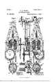
- FIG. 1 is an elevation of the complete machine, the front of the case being removed;
- Fig. 2 a detail elevation, looking from theleft of Fig. 1 and showing the mechanism whereby the tumbler-shafts and sheet-rolls are operated;
- Fig. 3 an edge view of the same;
- Fig. 4 an elevation from the right of Fig. l.
- Fig. 5 is a detail edge elevation showing the construction of the tumblers and the means for operating and holding them;
- Fig. 6, a front elevation of the same parts;
- a 1notor which is a 1notor,'preferably electric, and driven either by a battery or by a connection with some circuit, and this motor is belted to a shaft 4 at the right-hand upper end of the central compartment of the case.
- pinions the power from this shaft 4 is communicated .to a main shaft 5, which extends transversely of the central compartment.
- a cam-disk 7 Secured upon this shaft and within the frame 6, which provides a support for the tumbler-actuating mechanism, is a cam-disk 7, having in each sidethereof a cam-groove 8.
- the cam-grooves may be cut in the disk so as to operate the levers simultaneously in the same direction or in opposite directions.
- each of the levers has two outwardly-proj ecting pins or rolls 11.
- this segment is a small roller 1G, traveling therein as on a track, and a cord 17, having a weight 1S, extends from said roller over a pulley 19, supported above the plane of the shaft.
- the object of this segment is to cause the shaft after it has been carried over the center of said segment to be carried the remainder of its throw with a quick sharp action, due to the weight and roll acting on the segment.
- Each of the tumblers consists of a rectangular frame 20, whose upper and lower bars are p'rovided with longitudinally-extending grooves 20, in which advertisements or pictures may be secured by bending them and allowing their edges to spring into the grooves.
- Each of the frames is provided with two pins 21 at each end. These pins pass each through a hole in one of a pair of links 22, (see Fig. 5,) and said links being so placed that cach hole is in its center. From this comes the arrangement clearly seen at Figs. 5 and 6.
- the links are each connected so as to form two series by means of chains 23, so that when in the position shown at Figs. 5 and 6 the weight of each segment is support-ed by two separate and independent chains at each end.
- Weights 23 are preferably secured on the ends of the chains for the purpose of causing the chains and frames to hangstraight.
- a ratchet-wheel 21 Upon the same shaft with the cam-disk which operates the levers is secured a ratchet-wheel 21, whose teeth are engaged by a roll 25 on a transverse lever 26, one end of which is pivoted to the frame.
- the free end of said lever is connected to a downwardly-extendin g rod 27, which, through a pair of pins or pawls 2S, serves at each lifting' movement thereof to operate a pair of ratchet-wheels 29 one step.
- Said ratchet-wheels are secured upon transverse shafts 30, each carrying a sheet-roll 31, composed of the heads 32 and transverse wires 33, extended between the heads.
- a sheet adapted to bear advertising or other matter Upon each of these wires is hung a sheet adapted to bear advertising or other matter, as is shown in the Woolverton patent heretofore referred to.
- a wi re bail 34 In front of each sheet and piv- ⁇ otally attached to its wire at the ends is a wi re bail 34, whose function is to accelerate the drop of the sheet after the latter has passed out of the hold of a friction wheel or spring 35, which presses against the sheets at the rear of the roller to prevent their falling, except one at a time, as the roller is revolved by the rod operating through the pawls on the ratchet-wheel.
- each re volution of the cam-disk causes the pivoted pincarrying levers to oscillate about their fulcrum-points, and by their engagement with the pins on the transverse rock-shafts to turn said shafts on their axes.
- This turns theopenwire segment and raises two of the lines of chains and links, one at each end of the tumbler-frames.
- This turning action also lowers the other two lines of chains and links, and as this occurs the tumbler-frames begin to turn slowly upon their pins. This continues until the roll to which the weight is attached passes the center of the segment, when said weight by its action through the roll completes the throw of the segment by a quick sharp action.
Landscapes
- Physics & Mathematics (AREA)
- General Physics & Mathematics (AREA)
- Engineering & Computer Science (AREA)
- Theoretical Computer Science (AREA)
- Treatment Of Fiber Materials (AREA)
Description
3 Sheets- Sheet 1.
V. l ..11 em (No Model.)
TKE N-DRHIS PETERS CU., FNQTG1LITHO., WASMINETDN, D. C.
(No Model.) s sheets-sheet 2, C. A. WARD.
AADVBBJIISING cLooK. n No. 429,552. PafenteaJune s, 1.890.
(No Model.)
3 Sheets-Sheet 3.
C. A. WARD. ADVERTISING CLOCK.
Patented June 3, 1890.
INIII .nnuylgu EHLL'JIN UNITED STATES PATENT OFFICE.
CHARLES ADELBERT WARD, OF WATERBU'RY, CONNECTICUT.
ADVERTISING-CLOCK.
SPECIFICATION forming part of Letters Patent No. 429,552, dated June 3, 1890.
Application filed November 25, 1889. Serial No. 331,504. (No model.)
To all whom, it may concern.-
Be it known that I, CHARLEs ADELBERT WARD, a citizen of the United States, residing at Waterbury, in the county of New Haven and State of Connecticut, have invented certain'new and useful Improvements in Advertising-Clocks; and I do hereby declare the following to be a full, clear, and exact description of the invention, such as will enable others skilled in the art to which it appertains to make and use the same.
My invention relates to certain novel and useful improvements in machines for displaying advertisements, and which are preferably incased with a clock or music-box for the purpose of attracting attention-such, for instance, as shown in patent to Woolverton, No. 392,939, November 13, 1888; and the objects of my invention are to furnish a simple and positive construct-ion for the tumblers, which are located at the sides of the case; to furnish positively operated mechanism for the actuation of said tumblers; to furnish means for assisting the drop of the advertising sheets or leaves which are at .the central portion of the machine; and with these ends in view my invention consists inthe details of construction and combination of elements hereinafter to be fully set forth, and then recited in the claims.
In order that those skilled in the art to which my invention appertains may fully understand its construction and method of operation, I will describe the same in detail, reference being had to the accompanying drawings, which form a part of this specification, and in which- Figure 1 is an elevation of the complete machine, the front of the case being removed; Fig. 2, a detail elevation, looking from theleft of Fig. 1 and showing the mechanism whereby the tumbler-shafts and sheet-rolls are operated; Fig. 3, an edge view of the same; Fig. 4, an elevation from the right of Fig. l. In all these views the connection whereby the sheet-rolls are operated have been shortened, so as to bring them within the limits of the sheet. Fig. 5 is a detail edge elevation showing the construction of the tumblers and the means for operating and holding them; Fig. 6, a front elevation of the same parts; Fig. 7,
operating mechanism, and the side space being adapted to contain the tumblers.
2 is the clock, but as its construction and method of operation forms no part of my present invention I have not shown it in detail.
3 is a 1notor,'preferably electric, and driven either by a battery or by a connection with some circuit, and this motor is belted to a shaft 4 at the right-hand upper end of the central compartment of the case. By means of pinions the power from this shaft 4 is communicated .to a main shaft 5, which extends transversely of the central compartment. Secured upon this shaft and within the frame 6, which provides a support for the tumbler-actuating mechanism, is a cam-disk 7, having in each sidethereof a cam-groove 8.
9 are levers fulcrumed -upon a shaft 10, mounted in the frame, and each provided with a shoe running in one of the cam-grooves of the disk, so that as said disk revolves the levers will receive an oscillatory movement about their fulcrum. The cam-grooves may be cut in the disk so as to operate the levers simultaneously in the same direction or in opposite directions. At its upper end each of the levers has two outwardly-proj ecting pins or rolls 11.
12 are shafts of unequal length journaled across the top of the case, (see Fig. 1,) and at their inner adjacent ends they have three outwardly-projecting pins 13, so placed as to be engaged by the pins on the levers at each oscillation, and the shafts thereby turned upon their axes. The operation of these intermeshing pins is somewhat like that of gearteeth; but as the movement of the shafts is completed by other means it isI desirable to have more lost motion than a pair of ordinary geared segments Would afford. Upon each shaft immediately over the respective edges of the tumblers are secured two blocks 13, each provided with outwardly-projecting pins 14, to which the tumbler-chains may be attached, and having also a semicircular open-wire segment 15. In this segment is a small roller 1G, traveling therein as on a track, and a cord 17, having a weight 1S, extends from said roller over a pulley 19, supported above the plane of the shaft. The object of this segment is to cause the shaft after it has been carried over the center of said segment to be carried the remainder of its throw with a quick sharp action, due to the weight and roll acting on the segment. l
Each of the tumblers consists of a rectangular frame 20, whose upper and lower bars are p'rovided with longitudinally-extending grooves 20, in which advertisements or pictures may be secured by bending them and allowing their edges to spring into the grooves. Each of the frames is provided with two pins 21 at each end. These pins pass each through a hole in one of a pair of links 22, (see Fig. 5,) and said links being so placed that cach hole is in its center. From this comes the arrangement clearly seen at Figs. 5 and 6. The links are each connected so as to form two series by means of chains 23, so that when in the position shown at Figs. 5 and 6 the weight of each segment is support-ed by two separate and independent chains at each end. Weights 23 are preferably secured on the ends of the chains for the purpose of causing the chains and frames to hangstraight. Upon the same shaft with the cam-disk which operates the levers is secured a ratchet-wheel 21, whose teeth are engaged by a roll 25 on a transverse lever 26, one end of which is pivoted to the frame. The free end of said lever is connected to a downwardly-extendin g rod 27, which, through a pair of pins or pawls 2S, serves at each lifting' movement thereof to operate a pair of ratchet-wheels 29 one step. Said ratchet-wheels are secured upon transverse shafts 30, each carrying a sheet-roll 31, composed of the heads 32 and transverse wires 33, extended between the heads. Upon each of these wires is hung a sheet adapted to bear advertising or other matter, as is shown in the Woolverton patent heretofore referred to. In front of each sheet and piv-` otally attached to its wire at the ends is a wi re bail 34, whose function is to accelerate the drop of the sheet after the latter has passed out of the hold of a friction wheel or spring 35, which presses against the sheets at the rear of the roller to prevent their falling, except one at a time, as the roller is revolved by the rod operating through the pawls on the ratchet-wheel.
In the operation of my invention each re volution of the cam-disk causes the pivoted pincarrying levers to oscillate about their fulcrum-points, and by their engagement with the pins on the transverse rock-shafts to turn said shafts on their axes. This turns theopenwire segment and raises two of the lines of chains and links, one at each end of the tumbler-frames. This turning action also lowers the other two lines of chains and links, and as this occurs the tumbler-frames begin to turn slowly upon their pins. This continues until the roll to which the weight is attached passes the center of the segment, when said weight by its action through the roll completes the throw of the segment by a quick sharp action. This turns all the tumblers completely over, as will be readily understood, since the relative position of the two pairs of links which carry each tumbler has been reversed. This reversal of the tumblers occurs'at each rocking movement of the shafts, effected, as heretofore set forth, by the pin-carrying pivoted levers. At each revolution of the ratchetwheel on the shaft which bears the cam-,disk the vertical pawl-rod is lifted once for each tooth on the ratchet by means of the engagement of the latter with the pin on the transl verse lever. At each lift of said rod the ratchet-wheels of the sheet-rollers are turned one tooth, and the rollers consequently rotated one step. As a sheet passes from beneath the friction spring or roller the pivoted bail on its wire by bearing against the surface of the sheet serves to pull the latter downward, so as to cause it to fall earlier than it would if in no way assisted. Said sheet having so fallen hangs vertically, with the bail hanging in front of it, until the next sheet falls. As the roller turns, the sheets gradually rise at the rear under the roller or spring, and are there retained until released to fall into view at the front side.
I claim- 1. In an advertising-clock, the combination, with the movement secured within the case, of the rock-shafts journaled upon and ex' tending across the top of the case, the connections between the movement and said rock-shafts, the weights connected with and adapted to complete the movement of the segments, said segments being secured upon the rock-shafts, and the tnmblers depending from and operated by means of said rockshafts, substantially as set forth.
2. In an advertisingclock, the combination, with the rock-shafts journaled upon the top of tho case, and the tumblers depending from the outer ends of said rock-shafts and operated thereby, of the movement within the case, a pair of cam-actuated levers adapted to operate the rock-shafts, and the segments and the Weights connected thereto, whereby the throw of the rock-shafts in either direction is completed, substantially as specified.
3. In an advertising-clock of the character described, the combination, with the movement arranged within the case, of the camactuated levers extending upward from said movement, the rock-shafts journaled upon and extending across the top of the case, the sets of tuinblers supported at the sides of the case and operated by said rock-shafts, the pins engaged and adapted to be turned by said levers, and the segments and Weights IOO IIO
whereby the completion of the movement of the rock-shafts is accomplished, substantially as set forth.
4. In an advertising-clock of the character described, the combination, with theinclosingcase, of the main shaft 5, extending transversely of said case near its upper end, the disk provided with cam -grooves mounted upon said shaft, and the pivoted levers actuated by said grooves, the transversely-extended rock-shafts journaled on the top of the case and primarily actuated in both directions by said levers, and the weight-operated segments secured upon said shafts, whereby the full throw of the tumblers is insured, substantially as set forth.
5. In an advertising-clock of the character described, the combination, with the rockshafts, and means, as described, whereby proper axial movement is imparted thereto, of the tumbler-frames suspended from the ends of the rock-shafts, and the independent lines of chains and links pivotally secured to each of said tumblers and adapted to operate the latter to the extent of half a revolu tion, substantially as set forth.
6. In an advertising-clock of the character described, the combination, with the transversely-extended rock-shafts, and means, as described, whereby the appropriate movement in their bearings is imparted to said rock-shafts, of the lines of tumblers, each provided with two outwardly-projecting pins or trunnions at each end, the links journaled to said trunnions, and the connections between the ends of the several links, whereby the movements of the tumblers are accomplished and said tumblers reversed as to their visual surface, substantially as described.
7. In an advertising-clock of the character described, the combination, with the inclosing-case, of the main shaft and the tumbleractuating mechanism operated thereby, of a ratchet-wheel carried by the main shaft, a rod lifted by said ratchet, and the sheet-rollers journaled transversely of the case and rotated about their axes by said rod, substantially as set forth.
S. In anadvertising-clock, the combination, with the inclosing-case, of the main shaft journaled within said case, the ratchet-wheel carried by said main shaft, a pivoted lever resting upon and reciprocated vertically by the passage of the ratchet-teeth, the rod actuated by the lever, andv the sheet-rolls adapted to be rotated step by step by the rod, substantially as set forth.
9. The combination, in a machine as described, with the main shaft, and the sheetrolls having transverse wires whereon the sheets are hung, a connection between said shaft and rolls, and pivoted wire bails atnation, with the main shaft, of the cam-disk carried thereby, the transverse rock-shafts and the connection between them and the levers, the tumblers operated by said rock-shaft, the weight-operated segments for assisting the rotation of the shafts, the connecting-rod actuated by the ratchet-wheel on the main shaft, and the sheet-rollers operated step by step by the rod, substantially as and for the purpose set forth.
ll. In a machine of the character described, the combination, with the' sheet-roll and the means whereby it is operated, of a series of pivoted wire bails carried by said roll, each of said bails contiguous to and adapted to assist the fall of one of the sheets, substantially as set forth.
l2. In an advertising-clock or similar machine, the combination, with the series of tumbler-frames, each having its upper and lower bars grooved longitudinally, of vthe chains whereby said tumbler-frames are suspended and operated, and means, as described, whereby the alternate lifting movements are imparted to said chains, substantially as set forth.
13. In an advertising-clock, the combination, with the primary actuating movement and a suitable inclosing-case, of the rockshafts journaled at the top of the case, the lines of tumbler-frames depending from said rock-shaft, each of said frames having its upper and lower bars grooved longitudinally, and the independent series of chains and links, each eccentrically connected to each of the tumbler-frames and to the rockshafts, substantially as set forth.
14. In a machine of the character described, the combination, with a series of rectangular tumbler-frames arranged one above the other, of two pairs of chains, each pair connected to each of said tumbler-frames eccentrically to the center of said frames, and means, as described, whereby said chains are moved vertically in opposite directions and the IOO IIO
tumblers thereby reversed, substantially as set forth.
In testimony whereof I affix my signature in presence of two witnesses.
CHARLES ADELBERT IVARD.
Witnesses: S. H. IIUBBARD, W. J. TANNER.
Publications (1)
| Publication Number | Publication Date |
|---|---|
| US429552A true US429552A (en) | 1890-06-03 |
Family
ID=2498460
Family Applications (1)
| Application Number | Title | Priority Date | Filing Date |
|---|---|---|---|
| US429552D Expired - Lifetime US429552A (en) | Advertising-clock |
Country Status (1)
| Country | Link |
|---|---|
| US (1) | US429552A (en) |
-
0
- US US429552D patent/US429552A/en not_active Expired - Lifetime
Similar Documents
| Publication | Publication Date | Title |
|---|---|---|
| US429552A (en) | Advertising-clock | |
| US1066247A (en) | Rod-bending apparatus. | |
| US1112921A (en) | Changeable prismatic sign. | |
| US1718625A (en) | Advertising cabinet | |
| US1045221A (en) | Advertising device. | |
| US643224A (en) | Machine for making wire clothes-pin springs. | |
| US1102148A (en) | Figure toy. | |
| US785736A (en) | Exhibiting mechanism. | |
| US571015A (en) | Spilsburt pocock | |
| US1207241A (en) | Mechanical movement. | |
| US1180630A (en) | Advertising device. | |
| US1208729A (en) | Station-indicator. | |
| US591941A (en) | Shimer | |
| US319597A (en) | Automatic advertising device | |
| US907793A (en) | Sign-displaying mechanism. | |
| US1081001A (en) | Advertising-display mechanism. | |
| US369614A (en) | pullin | |
| US1099914A (en) | Advertising device. | |
| US398400A (en) | Mechanical movement | |
| US423578A (en) | Mechanical motion | |
| US475799A (en) | reuter | |
| US956142A (en) | Advertising device. | |
| US840409A (en) | Toy battle-ship. | |
| US469094A (en) | Motor | |
| US285499A (en) | melrose |