US4295418A - Chain broiler doctor blade - Google Patents
Chain broiler doctor blade Download PDFInfo
- Publication number
- US4295418A US4295418A US06/151,325 US15132580A US4295418A US 4295418 A US4295418 A US 4295418A US 15132580 A US15132580 A US 15132580A US 4295418 A US4295418 A US 4295418A
- Authority
- US
- United States
- Prior art keywords
- doctor blade
- frame
- chain conveyor
- chain
- rear portion
- Prior art date
- Legal status (The legal status is an assumption and is not a legal conclusion. Google has not performed a legal analysis and makes no representation as to the accuracy of the status listed.)
- Expired - Lifetime
Links
- 241000287828 Gallus gallus Species 0.000 title claims description 6
- 238000010276 construction Methods 0.000 claims 2
- 238000005452 bending Methods 0.000 description 1
- 230000009286 beneficial effect Effects 0.000 description 1
- 238000004140 cleaning Methods 0.000 description 1
- 230000000694 effects Effects 0.000 description 1
- 230000005484 gravity Effects 0.000 description 1
- 235000015220 hamburgers Nutrition 0.000 description 1
- 230000010355 oscillation Effects 0.000 description 1
- 125000006850 spacer group Chemical group 0.000 description 1
Images

Classifications
-
- A—HUMAN NECESSITIES
- A47—FURNITURE; DOMESTIC ARTICLES OR APPLIANCES; COFFEE MILLS; SPICE MILLS; SUCTION CLEANERS IN GENERAL
- A47J—KITCHEN EQUIPMENT; COFFEE MILLS; SPICE MILLS; APPARATUS FOR MAKING BEVERAGES
- A47J37/00—Baking; Roasting; Grilling; Frying
- A47J37/04—Roasting apparatus with movably-mounted food supports or with movable heating implements; Spits
- A47J37/044—Roasting apparatus with movably-mounted food supports or with movable heating implements; Spits with conveyors moving in a horizontal or an inclined plane
Definitions
- a broiler has a chain conveyor with cross rods impelled to travel around sprockets.
- the doctor blade at intermediate, transverse side edges fits loosely in slot bearings defined between uprights in the broiler frame and brackets adjustably and removably secured thereto.
- the doctor blade extends freely and substantially below the intermediate, side edges and so is impelled by gravity to urge the upper transverse edge yieldably toward the conveyor.
- the bearing brackets at the top preferably are bent away from the frame uprights to provide freely available slot bearings in which the intermediate edges can approximately pivot.
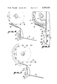
- FIG. 1 is an end elevation of a portion of a chain broiler in which the doctor blade is installed, portions being broken away to reduce the size of the figure.
- FIG. 2 is a side elevation of the structure shown in FIG. 1 with portions again being broken away to reduce the size of the figure.
- FIG. 3 is a cross-section, the plane of which is indicated by the line 3--3 of FIG. 1.
- FIG. 4 is another cross-section, the plane of which is indicated by the line 4--4 of FIG. 1.
- FIG. 5 is a further cross-section, the plane of which is indicated by the line 5--5 of FIG. 1.
- Machines for broiling patties such as hamburgers are well known, an example being shown in U.S. Pat. No. 4,188,866.
- Such machines include a frame on which cross shafts are mounted carrying pairs of sprockets around which end chains are trained.
- Conveyor rods extend transversely between the end chains or themselves form the chains and advance the patties in proximity with appropriate broiling elements so that the patties cook.
- the cooked patties bend or deform and sometimes are difficult to dislodge from the conveyor cross rods.
- the machine frame has a pair of uprights 7 and 8 on which is mounted a pair of side bearings 9 receiving a conveyor shaft 11 appropriately driven.
- a conveyor shaft 11 appropriately driven.
- On that shaft there are sprockets 12 and 13 interengaged with a conveyor chain 14 inclusive of a plurality of cross rods 16. These follow a generally arcuate path as they travel around the sprockets 12 and 13 at the discharge end of the patty conveying path.
- FIG. 5 One relationship of a cooked patty to the conveyor chain 14 is illustrated particularly in FIG. 5.
- a doctor blade generally designated 21.
- This is a transversely extending, formed plate at its opposite side edges having intermediate, indented bearing shoulders 22 and 23 in transverse alignment.
- Each of the shoulders 22 and 23 fits in an adjacent one of a pair of bearings 24 and 26.
- These bearings are inclusive of base plates 27 secured to the adjacent uprights 7 and 8 by removable fasteners 28.
- Each of the plates 27 is supplemented by a band 31 welded to the plate but at its upper end struck or deformed outwardly to provide a bearing wall 32.
- a bearing slot 33 With the adjacent upright 7 or 8 and with the plate 27 acting as a spacer, there is provided a bearing slot 33 somewhat wider at the upper end than it is at the lower end.
- bearing shoulders 22 and 23 Designed to span the frame of the machine and to be pivotally supported thereon are the bearing shoulders 22 and 23.
- the shoulders can rotate slightly in and have free bearing in the slots 33 so provided.
- the doctor blade 21 is extended upwardly from the intermediate bearing shoulders 22 and 23 and is bent outwardly and rearwardly somewhat so as to have an upper edge 36 that can lie very close to or even against the rods 16 as they round the sprockets 12 and 13.
- fingers 37 and 38 extending from the plate 21 and adapted to lie against the successively approaching transverse rods 16. Since the rods 16 are spaced, there is a little beneficial oscillation given to the doctor blade.
- the plate 21 In order properly to impel the fingers and to maintain the doctor blade in its proper position, the plate 21 is extended inwardly and downwardly below the previously described portions thereof and certainly below the shoulders 22 and 23.
- the blade terminates in a counterweight portion 41, as particularly shown in FIGS. 4 and 5, the weight or mass of the counterweight portion acting about the shoulders 22 and 23 as fulcra. This is sufficient to urge the upper portion of the doctor blade into close juxtaposition with the rods 16. In this way the leading edge 36 is maintained in the path of any advancing patties and is always held in position, with some possible yielding, to make sure that the patties are removed from the rods and fall freely to a subsequent handling mechanism.
- the doctor blade When, from time to time, the doctor blade needs adjustment, cleaning or replacement, it is readily removed by lifting the shoulders 22 and 23 from the slots near the walls 32.
- the doctor blade can be replaced by a similar unit or can be returned after servicing. While the intermediate shoulders of the doctor blade serve as excellent bearings, the angularity of the bearing walls 32 is such as to preclude excessive movement of the doctor blade.
- the counterweight effect of the doctor blade eliminates the necessity of springs or the like which might cause difficulty.
Landscapes
- Engineering & Computer Science (AREA)
- Food Science & Technology (AREA)
- Confectionery (AREA)
Abstract
Description
Claims (2)
Priority Applications (1)
| Application Number | Priority Date | Filing Date | Title |
|---|---|---|---|
| US06/151,325 US4295418A (en) | 1980-05-19 | 1980-05-19 | Chain broiler doctor blade |
Applications Claiming Priority (1)
| Application Number | Priority Date | Filing Date | Title |
|---|---|---|---|
| US06/151,325 US4295418A (en) | 1980-05-19 | 1980-05-19 | Chain broiler doctor blade |
Publications (1)
| Publication Number | Publication Date |
|---|---|
| US4295418A true US4295418A (en) | 1981-10-20 |
Family
ID=22538245
Family Applications (1)
| Application Number | Title | Priority Date | Filing Date |
|---|---|---|---|
| US06/151,325 Expired - Lifetime US4295418A (en) | 1980-05-19 | 1980-05-19 | Chain broiler doctor blade |
Country Status (1)
| Country | Link |
|---|---|
| US (1) | US4295418A (en) |
Cited By (4)
| Publication number | Priority date | Publication date | Assignee | Title |
|---|---|---|---|---|
| US4583451A (en) * | 1984-07-12 | 1986-04-22 | Kanagy Jonas J | Apparatus for automatically cooking products made of batter, such as pancakes |
| EP0655215A1 (en) * | 1993-11-29 | 1995-05-31 | G.S. Blodgett Corporation | Improved belt cooking apparatus |
| US20070039804A1 (en) * | 2005-08-18 | 2007-02-22 | Honda Motor Co., Ltd. | Bolt diversion system |
| US9687110B2 (en) | 2013-12-04 | 2017-06-27 | Teca Technologies Limited | Pancake maker apparatus, methods and systems |
Citations (6)
| Publication number | Priority date | Publication date | Assignee | Title |
|---|---|---|---|---|
| US2285321A (en) * | 1939-02-17 | 1942-06-02 | Metalwash Machinery Co Inc | Delivery table |
| US2576633A (en) * | 1947-12-03 | 1951-11-27 | T & T Vicars Ltd | Stripping device for conveyers |
| US3202260A (en) * | 1962-10-17 | 1965-08-24 | Philadelphia Belting Co | Conveyor |
| US3229616A (en) * | 1964-04-29 | 1966-01-18 | Reese Sy | Vertical broiler |
| US4151791A (en) * | 1978-01-23 | 1979-05-01 | Npi Corporation | Energy conserving broiler |
| US4188866A (en) * | 1977-06-16 | 1980-02-19 | Npi Corporation | Patty broiler |
-
1980
- 1980-05-19 US US06/151,325 patent/US4295418A/en not_active Expired - Lifetime
Patent Citations (6)
| Publication number | Priority date | Publication date | Assignee | Title |
|---|---|---|---|---|
| US2285321A (en) * | 1939-02-17 | 1942-06-02 | Metalwash Machinery Co Inc | Delivery table |
| US2576633A (en) * | 1947-12-03 | 1951-11-27 | T & T Vicars Ltd | Stripping device for conveyers |
| US3202260A (en) * | 1962-10-17 | 1965-08-24 | Philadelphia Belting Co | Conveyor |
| US3229616A (en) * | 1964-04-29 | 1966-01-18 | Reese Sy | Vertical broiler |
| US4188866A (en) * | 1977-06-16 | 1980-02-19 | Npi Corporation | Patty broiler |
| US4151791A (en) * | 1978-01-23 | 1979-05-01 | Npi Corporation | Energy conserving broiler |
Cited By (5)
| Publication number | Priority date | Publication date | Assignee | Title |
|---|---|---|---|---|
| US4583451A (en) * | 1984-07-12 | 1986-04-22 | Kanagy Jonas J | Apparatus for automatically cooking products made of batter, such as pancakes |
| EP0655215A1 (en) * | 1993-11-29 | 1995-05-31 | G.S. Blodgett Corporation | Improved belt cooking apparatus |
| US20070039804A1 (en) * | 2005-08-18 | 2007-02-22 | Honda Motor Co., Ltd. | Bolt diversion system |
| US7383941B2 (en) | 2005-08-18 | 2008-06-10 | Honda Motor Co., Ltd. | Bolt diversion system |
| US9687110B2 (en) | 2013-12-04 | 2017-06-27 | Teca Technologies Limited | Pancake maker apparatus, methods and systems |
Similar Documents
| Publication | Publication Date | Title |
|---|---|---|
| US2125353A (en) | Moving target | |
| US2897536A (en) | Poultry boning machine | |
| JP4074583B2 (en) | Rotating oven | |
| US4295418A (en) | Chain broiler doctor blade | |
| US2516499A (en) | Conveyer for eviscerating apparatus | |
| US2602392A (en) | Frankfurter grill | |
| US4077311A (en) | Food roasting or boiling apparatus and method | |
| US2822569A (en) | Fish filleting machine | |
| CN210882752U (en) | Steamed bun arrangement machine | |
| US2286013A (en) | Doughnut machine | |
| US1763738A (en) | Conveyer | |
| US2340783A (en) | Pivoted flight conveyer | |
| US4207810A (en) | Cup and cover turnover mechanism for English muffin griddles | |
| US2359070A (en) | Conveyer mechanism | |
| US3279634A (en) | Transfer apparatus | |
| US2233149A (en) | Counting machine for counting record cards, checks, coupons, and the like | |
| DE470084C (en) | Height conveyor with roller guide for the carrier rake articulated with the endless chains | |
| JPH038647Y2 (en) | ||
| US2684752A (en) | Conveyer for corn cutting machines | |
| JP3412041B2 (en) | Automatic pottery machine | |
| GB703099A (en) | A document filing appliance | |
| US1791044A (en) | Sheet-spacing mechanism for tin pots | |
| CN214758874U (en) | Manual dumpling machine | |
| US967758A (en) | Discharge-conveyer. | |
| US2682961A (en) | Depanning machine |
Legal Events
| Date | Code | Title | Description |
|---|---|---|---|
| STCF | Information on status: patent grant |
Free format text: PATENTED CASE |
|
| AS | Assignment |
Owner name: NIECO CORPORATION, Free format text: CHANGE OF NAME;ASSIGNOR:N.P.I. CORPORATION;REEL/FRAME:004087/0481 Effective date: 19821012 |
|
| AS | Assignment |
Owner name: ALCO STANDARD CORPORATION, P.O. BOX 834, VALLEY FO Free format text: ASSIGNMENT OF ASSIGNORS INTEREST.;ASSIGNOR:NIECO CORPORATION;REEL/FRAME:004824/0363 Effective date: 19880113 Owner name: ALCO STANDARD CORPORATION, A CORP. OF DE,PENNSYLVA Free format text: ASSIGNMENT OF ASSIGNORS INTEREST;ASSIGNOR:NIECO CORPORATION;REEL/FRAME:004824/0363 Effective date: 19880113 |
|
| AS | Assignment |
Owner name: NIECO CORPORATION A CORPORATION OF DE, DELAWARE Free format text: ASSIGNMENT OF ASSIGNORS INTEREST.;ASSIGNOR:ALCO STANDARD CORPORATION, AN OH CORPORATION;REEL/FRAME:005990/0740 Effective date: 19920127 |