US4279317A - Magnetic coupling for a weighing balance assembly - Google Patents
Magnetic coupling for a weighing balance assembly Download PDFInfo
- Publication number
- US4279317A US4279317A US06/080,803 US8080379A US4279317A US 4279317 A US4279317 A US 4279317A US 8080379 A US8080379 A US 8080379A US 4279317 A US4279317 A US 4279317A
- Authority
- US
- United States
- Prior art keywords
- sample
- weighing
- weight
- support shaft
- fat
- Prior art date
- Legal status (The legal status is an assumption and is not a legal conclusion. Google has not performed a legal analysis and makes no representation as to the accuracy of the status listed.)
- Expired - Lifetime
Links
Images

Classifications
-
- G—PHYSICS
- G01—MEASURING; TESTING
- G01G—WEIGHING
- G01G23/00—Auxiliary devices for weighing apparatus
- G01G23/06—Means for damping oscillations, e.g. of weigh beams
- G01G23/10—Means for damping oscillations, e.g. of weigh beams by electric or magnetic means
-
- Y—GENERAL TAGGING OF NEW TECHNOLOGICAL DEVELOPMENTS; GENERAL TAGGING OF CROSS-SECTIONAL TECHNOLOGIES SPANNING OVER SEVERAL SECTIONS OF THE IPC; TECHNICAL SUBJECTS COVERED BY FORMER USPC CROSS-REFERENCE ART COLLECTIONS [XRACs] AND DIGESTS
- Y10—TECHNICAL SUBJECTS COVERED BY FORMER USPC
- Y10S—TECHNICAL SUBJECTS COVERED BY FORMER USPC CROSS-REFERENCE ART COLLECTIONS [XRACs] AND DIGESTS
- Y10S177/00—Weighing scales
- Y10S177/05—Magnets
Definitions
- This invention relates to a magnetic coupling device for coupling the weight bearing stem of a weighing balance to the internal mechanism of the balance, and more particularly to a magnetic coupling device for use in a meat analyzer as disclosed in copending application Ser. No. 080,802, filed Oct. 1, 1979 and entitled “Method and Apparatus for Analysis of Meat Products," and Ser. No. 080,841, filed Oct. 1, 1979 entitled “Use of Acid as an Analysis Aid in Salted Meat Samples,” both filed on even date herewith.
- Precision weighing balance mechanisms are quite sensitive to abrupt changes in weight loads such as are caused by the loading and unloading of samples, the removal and insertion of sample holders and the like, and accidental bumps and jars by the operator of the weighing platform.
- the weighing platform is connected to the internal weighing mechanism by means of an elongated single shaft force transmitting element, the almost unavoidable bumping or jarring of the platform during sample loading and unloading or insertion and removal of holder parts causes potentially damaging movements, torques, and/or forces to be transmitted by the shaft to the internal weighing mechanism.
- the internal weighing mechanism is highly vulnerable to even slight bumps and jars which unavoidably occur during removal and loading of a sample.
- the present invention meets that need by providing for a magnetic coupling between the shaft and the internal weighing mechanism which permits transverse movement of the shaft when it is bumped or jarred. Because the shaft is no longer rigidly attached to the weighing mechanism, no damaging forces or torques are transmitted when the shaft or attached weighing platform are jarred. Rather, the shaft moves transversely in response to a force applied normal to its long axis. The magnetic attraction between the shaft and the coupling is sufficient to insure that the shaft remains upright during normal weighing operations and returns to an upright position after encountering a sideways bump or jar.
- the magnetic coupling is utilized to connect a sample support shaft to a weighing mechanism in a meat analyzing device.
- the meat analyzer determines the fat, moisture, and protein content of samples by heating them with microwave energy in an oven to drive off moisture as water vapor and render fat as a liquid which is collected and separately weighed.
- the weighing balance assembly is located exteriorly of the microwave oven and is used to measure the weight of meat samples before, during, and after cooking.
- the upper portion of the sample support shaft which extends into the oven through a choke seal in the base thereof is fabricated of a plastic or ceramic material which is not affected by microwave energy. This upper portion of the shaft is secured to a lower ferromagnetic portion of the shaft which forms a part of the magnetic coupling.
- Attached to the internal weighing mechanism of the balance assembly and extending therefrom is a holder which has a permanent magnet seated therein.
- the holder has a generally cylindrically shaped opening into which the lower portion of the sample support shaft is fitted and coupled to the magnet.
- the sidewalls of the holder are flared outwardly to permit the shaft to rock from the vertical while remaining coupled to the magnet.
- the diameter of the choke seal opening in the base of the oven is such that the shaft has sufficient clearance to rock slightly when jarred or bumped.
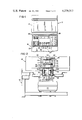
- FIG. 1 is a front view of the apparatus of the present invention illustrating the control panel and microwave oven;
- FIG. 2 is a view of the weighing apparatus, sample holder assembly, and fat collecting dish and dish support assembly in their respective positions during the cooking of the sample;
- FIG. 3 is a view of the portion of the apparatus shown in FIG. 2, with the various elements shown in their respective positions after cooking has been terminated;
- FIG. 4 is a side view of the mechanism which raises and lowers the dish support assembly.
- FIG. 5 is a detailed sectional view of the magnetic coupling of the stem of the weighing balance to the base thereof.
- Analysis of food material is provided by rendering or "cooking" the sample to release from it moisture, primarily in the form of vapor, and fat, primarily as liquid which is collected separately from the solid residue and removed from the scale to avoid fluctuations in weight readings.
- moisture primarily in the form of vapor
- fat primarily as liquid which is collected separately from the solid residue and removed from the scale to avoid fluctuations in weight readings.
- a comminuted meat sample is selected such that the sample weight is in the range of 70 to 80 grams.
- the reason for this is that the "cooking" cycle may be maintained short, e.g., 2 to 41/2 minutes.
- the term "cooking" in accordance with this invention is meat heated short of charring but far too well cooked to be edible in the normal sense.
- the use of microwave energy offers the singular advantage of generating heat throughout the sample so that it is uniformly and evenly heated. The energy from the source penetrates the sample causing oscillation of dipolar molecules, such as water, which attempt to align themselves with the polarity of the electromagnetic field, and thereby generate heat uniformly throughout the sample. The moisture, or water is vaporized and released directly as vapor.
- the fat molecules are excited sufficiently by the microwave energy to cause melting of the fat which then drips from the sample into a collection dish.
- melting of the fat By heating the sample short of charring, decomposition of substantial amounts of protein and fat is avoided even though some fat, moisture, and protein remains in the solid residue.
- the microwave cooking thus does not remove all of the fat or moisture, but this has been found not to be critical to the determination of the percentages of these components as taught in above-mentioned U.S. Pat. Nos. 3,890,825 and 3,916,670. It has also been observed that some of the protein is removed with the moisture by decomposition and vaporization. These factors are compensated for by generating a set of constants which are a function of oven design, i.e., spacing between the microwave energy source and sample, intensity of energy source, and rate of heating and type of meat. Also a factor is the loss of fat, protein, etc., due to spattering and the vaporization of some of these components.
- any microwave oven will have a set of constants which can be calculated, the constants being determined easily by a simple calibration procedure, and being valid for each oven of the same design, although it may vary from one design of oven to the next.
- the procedure for developing such constants is discussed in the above-mentioned patents and is incorporated herein by reference. Those sampling techniques and use of multiple regression analysis have been extended to include the determination of constants for salt content and temperature in the present invention.
- the analysis system operates as follows.
- the sample holder assembly, sample holder, and sample holder cover are first weighed to establish an initial tare weight which is then stored.
- the fat collection dish is then lowered onto the sample holder assembly and weighed to establish a second combined tare weight which is stored. (It should be understood that whenever “collection dish” is mentioned, this also includes a dish paper and watchglass which are contained in the collection dish and help to prevent spattering.)
- the collection dish is then raised off of the sample holder assembly in preparation for the cooking cycle.
- a prepared sample of meat is then placed in the sample holder, covered, and loaded onto the sample holder assembly.
- the cooking cycle is initiated and continued until the rate of weight loss of the sample falls below a predetermined value.
- the fat collection dish is maintained off the sample holder assembly so that the rendered fat it collects does not cause any fluctuations in weight readings.
- the oven is shut off and the fat containing collection dish is lowered into the sample holder assembly where the combined weight of the sample holder assembly, sample holder, sample holder cover, collection dish, sample residue, and rendered fat is recorded.
- the residue is then removed from the balance and the combined weight of the sample holder assembly, sample holder, sample holder cover, collection dish, and rendered fat is recorded.
- the moisture, fat, and protein content of the sample may then be calculated using equations which will be set forth below.
- the present system may be used to determine only fat content in contrast to determination of each of moisture, fat, and protein, or may be used to determine only moisture. If used to determine only protein, this can be done by determining fat and moisture but reporting only the protein results.
- this automated system includes a weighing balance assembly 10 incorporated beneath a microwave oven 12 which is supported on a suitable cabinet 14.
- the oven is a standard type of microwave oven using a magnetron with a frequency of 2450 megahertz, although frequencies of between 900 to 2500 megahertz may be used.
- This oven may be basically the same as a Model M312 microwave oven commercially available from the Hobart Corporation.
- Oven 12 includes a hinged door 16.
- a control panel 20 which includes a master power (ON-OFF) switch 22 as well as the following controls.
- RESET switch 24 interrupts the program and returns control to the start of the program.
- CLEAR switch 26 clears any digits displayed in a window 28.
- CONT switch 30 when touched indicates that a command has been completed and continues the program to the next command. By touching switches NO 32 or YES 34 an operator can answer questions displayed in window 28. Finally, numbers entered into the program by touching digit switches 0-9 will be displayed in the window 28.
- a printer 23 records and displays information on a paper ticket.
- the weighing balance assembly 10 includes a precision balance such as a modified Model 5300 top loading balance commercially available from the Voland Corporation of New Rochelle, New York, having a sample holder assembly 36 mounted within the oven cavity on the pedestal stem 38 of the balance.
- a precision balance such as a modified Model 5300 top loading balance commercially available from the Voland Corporation of New Rochelle, New York, having a sample holder assembly 36 mounted within the oven cavity on the pedestal stem 38 of the balance.
- the upper portion 80 of stem 38 is fabricated of a plastic, such as polypropylene, or other material substantially unaffected by microwave energy.
- a slot 82 which is adapted to straddle pin 84 in boss 86 (illustrated in FIGS. 2 and 3) to provide proper alignment of the sample holder assembly 36 in the system.
- the opposite tip 88 of upper portion 80 of the stem is adapted to fit into a hole bored in lower portion 90 of stem 38 and is held therein by suitable means such as set screw 92.
- Lower portion 90 of stem 38 is fabricated of a ferromagnetic material and is magnetically coupled to magnet 93 having poles 95 and seated in holder 94.
- a suitable magnet for use in the device has been found to be a BM-1908 ⁇ 3/4 magnet commercially available from Bunting Magnetics Co., Elk Grove Village, Illinois. The magnet is held in place by suitable means such as a set screw 96.
- Stem 38 is maintained in proper alignment in holder 94 by means of slot 98 which straddles pin 100.
- a disc-like shield 102 protects the weighing mechanism from any possible fat drippings which may inadvertently escape from the oven.
- Holder 94 is secured by suitable means such as screw 104 to the balance mechanism 106.
- the upper portion 108 of the inner wall of holder 94 flares outwardly at an angle of about 7.5° from vertical to permit stem 38 to rock slightly away from the vertical while in the holder.
- the vertical movement of the stem is limited by the clearance between the stem and a 1/4 wavelength choke seal which substantially eliminates any leakage of microwave energy from the opening in the oven bottom wall. Typically, this clearance is about 1/4 inch.
- the magnetic coupling normally maintains the stem in a desired vertical position while still permitting a slight rocking motion of the stem relative to the magnet. This rocking motion, without magnetically uncoupling the stem, avoids the problem of transmitting possibly damaging forces or torques to the internal mechanism of the weighing device.
- the attraction between the magnet and the metallic lower portion of the stem insures that the stem will return to vertical once any external forces such as bumping or jarring have been removed from the stem and sample holder assembly.
- a weighing balance having the weighing platform separated from the body portion by an elongated single shaft force transmitting element as does the Voland device is preferable for the present apparatus
- other forms of weighing apparatus including balances of the type wherein the force transducer is located inside the microwave oven cavity and only electrical wires are conducted to the cavity exterior if suitable changes are made in the apparatus.
- Balances which are totally mounted in the oven cavity and conduct electrical signals to the exterior would for example require suitable shielding and filtering devices to protect the balance transducers from microwave heating and to prevent microwave radiation from being conducted to the exterior of the heating cavity by the balance signal wiring.
- Sample holder assembly 36 includes a base member 40 having a suitable connecting means such as boss 86 and pin 84 for releasably attaching the assembly to stem 38 of the balance.
- Boss 86 consists of a hollow shaft which fits over stem 38 and contains an alignment pin 84 to properly align the assembly on the stem.
- a pair of upstanding end walls 42 and 44 support an annular disc 46 which is attached thereto. The opening in disc 46 is proportioned to receive a sample holder 48 which may be a perforated watchglass.
- a sample 49 of prepared meat is placed on sample holder 48 and is then covered by a sample holder cover 50.
- sample holder cover 50 is also perforated to permit the escape of moisture from the sample as vapor during the cooking cycle.
- Both holder 48 and cover 50 may be formed of Pyrex glass or polytetrafluoroethylene (Teflon, a trademark of the duPont Company) or other suitable material which is nonresponsive (i.e., not heated) or only mildly responsive to microwave electromagnetic energy.
- a dish support assembly generally indicated at 52.
- This assembly includes a pair of vertically extending shafts 54 and 56 which extend through biushings 58 and 60, respectively, and rest on platform 62.
- Bushings 58 and 60 extend through the base of oven 12 into cabinet 14 and are sealed in the same manner as stem 38 to prevent leakage of microwave energy from the oven during operation.
- An annular disc-shaped support element 64 is attached to shafts 54 and 56 and surrounds stem 38. It has mounted on opposite sides thereof, a pair of upstanding members 66 and 68 which are adapted to support a dish 70.
- Dish support assembly 52 is raised or lowered by raising or lowering platform 62. As best shown in FIG. 4, this is accomplished by a drive means 72 suitably connected to a shaft 74 which turns cam 76. Cam 76 is in direct contact with the underside of platform 62. Rotation of cam 76 causes platform 62, which is hinged at one end to support member 78 which is attached to a portion of cabinet 14, to raise and lower shafts 54 and 56.
- a limit switch (not shown) cuts off drive means 72 when the upper or lower (shown in dashed lines in FIG. 4) limit of platform movement is achieved.
- dish 70 is raised off of sample holder assembly 36, as shown in FIG. 2, during the cooking cycle. Fat rendered from the sample during cooking is collected in dish 70 off of the weighing scale, avoiding erratic fluctuations in weight readings caused by explosions and spattering or dripping of the hot fat in the dish. After the cooking cycle has been terminated, dish 70 is lowered onto sample holder assembly 36 as shown in FIG. 3 where it is weighed.
- the weighing balance device includes a digital electronic output and a microprocessor-controller as taught in the above-mentioned U.S. Pat. Nos. 3,890,825 and 3,916,670.
- the microprocessor-controller properly sequences the operation of the device and provides outputs to the display window 28 and printer 23.
- the operation of the microprocessor-controller is detailed in the above-mentioned patents and is herein incorporated by reference.
- the power is turned on by pressing ON switch 22. Then, the date, run number, meat type code, and temperature of the prepared sample are successively entered by the operator alternatively touching the appropriate digit switches and then the CONT switch 30 on the control panel.
- the command "PREPARE OVEN" is displayed in window 28. Then, the operator opens the oven door 16 and loads the sample holder assembly 36 including the sample holder 48 and sample cover 50 onto the weighing balance. At this time, also, collection dish 70 is loaded onto dish support assembly 52 which is in a raised position. After the operator closes the door 16 and touches CONT switch 30, a first tare weight (denoted SPT) of the sample support assembly, holder, and cover is taken and stored. The dish support assembly is then lowered causing dish 70 to be deposited onto the base member 40 of the sample holder assembly and a second tare weight (denoted S and D) which includes the weight of the collection dish is taken and stored.
- a first tare weight denoted SPT
- the microprocessor makes a calculation to confirm that the weight value of the collection dish (denoted as DSH) is within predetermined expected limits and that the operator has placed the dish on the dish support assembly. (The weight value DSH is not saved by the microprocessor.)
- the microprocessor causes the dish support assembly 52 to be raised so that the dish 70 is off of the sample holder assembly base member 40.
- Each actuation of the dish support assembly 52 to raise or lower the dish 70 is controlled by the microprocessor through its selective operation of the drive means 72 in a conventional manner.
- the microprocessor displays a "LOAD SAMPLE" command on display window 28. Then, the operator loads a prepared sample between sample holder 48 and sample cover 50. Samples of fresh meat are prepared by grinding a sample through a conventional meat grinder and then mixing it to obtain a uniform composition. For best results, both the amount of mixing and temperature of the sample are controlled to enable accurate calibration of the analyzer and accurate sample analysis. It has been found that mixing for about 30 seconds at from 30°-50° F. produces satisfactory results.
- SAM initial sample weight calculation
- the operation for the analysis of a salted meat sample differs slightly from fresh meat analysis operation. This is due to the fact that meat proteins, as with many food proteins, have the ability to bind or encapsulate fat in an emulsion.
- the addition of salt to meat blends in meat processing operations aids in solubilizing the meat proteins and enables a greater amount of binding of fats.
- temperature is an important factor in forming emulsions in a blended meat product, with higher temperatures (i.e., 50°-60° F.) producing more stable emulsions as opposed to lower temperatures (i.e., 30°-40° F.).
- varying the salt content, temperature, and amount of mixing of any meat blend varies the amount of fat bound in a meat sample of this blend and varies the resulting amount of fat rendered from a sample during heating.
- Accurate calibration becomes impossible for salted and blended samples which have undergone an indeterminate amount of mixing at an unknown temperature in the processing operation and during sample preparation.
- all sample preparations for a finished sample should be carried out for a definite time (i.e., 30 seconds to 1 minute) and at a temperature between 30° and 50° F.
- citric acid for this purpose produces satisfactory results from the standpoint of ease of handling and production of samples from which accurate calibration measurements can be taken, although other acids may be utilized.
- a preferred form of citric acid is an encapsulated citric acid product commercially available from Durkee Foods, Inc. under the name Durkote citric acid (SR) (small granular).
- SR Durkote citric acid
- the encapsulated acid is packaged in the form of a pillow or capsule.
- the citric acid is encapsulated in a fatty material which melts at 145°-150° F.
- the citric acid product may be mixed with a meat sample and the desirable pH lowering effect of the acid taken advantage of during cooking of the sample. It has been found that the addition of about 3 grams of this acid product to a 70-80 gram sample of meat produces satisfactory results.
- the microprocessor utilizes the proper calibrated constant values for the program commands and required calculations.
- the operator In addition to entering the appropriate meat type code, run number, and sample temperature, the operator must input the percentage of salt (salt weight divided by meat weight) in the sample to be analyzed.
- the operator then prepares the oven as described above. However, when the CONT switch 30 is touched, the display window 28 will indicate "PRELOAD SAMPLE” instead of "LOAD SAMPLE” as described above.
- the contents of an acid pillow is added to the meat sample and mixed.
- the acid pillow preferably contains citric acid which acts to aid in the release of fat and moisture during the subsequent cooking of the sample.
- the microprocessor now turns on the power to oven 12 and cooking of the sample is commenced.
- the command "IN PROCESS" is displayed in window 28 during cooking.
- the microprocessor continuously monitors the change in weight of the sample during cooking until the time rate of change of weight loss is less than a predetermined value.
- the oven is turned off.
- dish 70 is lowered onto sample holder assembly 36 by activation of drive means 72.
- the total sample weight (denoted CTF) including the weight of the sample residue, fat, sample holder, sample holder cover, and holder assembly is then measured after a 10 second delay. This delay provides for the lapse of a period of time sufficient for spattering (or dripping) and explosions of rendered fat in the dish to have substantially subsided by the time the weight measurement is taken.
- the microprocessor causes the caption "REMOVE RESIDUE" to be displayed.
- the operator then opens the oven door 16, removes the residue from the sample holder assembly, closes the door, and touches CONT switch 30 to cause the weight (denoted FNL) of the rendered fat, cover, holder, and holder assembly to be measured and stored.
- the microprocessor then automatically raises dish support assembly 52 with dish 70 off of the weighing balance in preparation for the next sample analysis.
- the microprocessor can then calculate the percentages of fat, moisture, and protein in the sample. These final percentages (TPF, TPM, and TPP) are then displayed on window 28 and printed out by the printer 23 for a permanent record of the sample.
- SPT Weight of sample holder and cover and sample holder assembly.
- DSH S and D-SPT, weight of collection dish including watchglass and paper.
- SAM Initial weight of sample.
- ACD Weight of acid.
- CTF Weight at cut-off of cooking of sample residue and rendered fat plus sample holder and cover, sample holder assembly, and collection dish.
- FAT Weight of rendered fat.
- MST Weight of vaporized moisture.
- FNL Weight of rendered fat plus sample holder and cover, sample holder assembly, and collection dish.
- RPF Raw percent fat or fat percent by weight.
- RPM Raw percent moisture or moisture percent by weight.
- TPF True percent fat--correlated value.
- TPM True percent moisture--correlated value.
- TPP True percent protein--correlated value.
Abstract
Description
DSH=S and D-SPT
SAM=(SAM+SPT)-SPT
SAM and ACD=(SAM+SPT+ACD)-SPT
ACD=(SAM+ACD)-SAM
CTF=S and D+SAM-MST
FNL=S and D+FAT
FAT=FNL-S and D
MST=S and D+SAM-CTF
RPF=FAT/SAM
RPM=MST/SAM
TPF=K.sub.o ±K.sub.1 (RPF)±K.sub.2 (RPM)±K.sub.3 (TEMP)±K.sub.4 (SALT)
TPM=K.sub.o ±K.sub.1 (RPF)±K.sub.2 (RPM)±K.sub.3 (TEMP)±K.sub.4 (SALT)
TPP=K.sub.1p -K.sub.2p (TPF)-TPM-SALT %
Claims (5)
Priority Applications (2)
| Application Number | Priority Date | Filing Date | Title |
|---|---|---|---|
| US06/080,803 US4279317A (en) | 1979-10-01 | 1979-10-01 | Magnetic coupling for a weighing balance assembly |
| CA000360716A CA1143389A (en) | 1979-10-01 | 1980-09-22 | Magnetic coupling for a weighing balance assembly |
Applications Claiming Priority (1)
| Application Number | Priority Date | Filing Date | Title |
|---|---|---|---|
| US06/080,803 US4279317A (en) | 1979-10-01 | 1979-10-01 | Magnetic coupling for a weighing balance assembly |
Publications (1)
| Publication Number | Publication Date |
|---|---|
| US4279317A true US4279317A (en) | 1981-07-21 |
Family
ID=22159720
Family Applications (1)
| Application Number | Title | Priority Date | Filing Date |
|---|---|---|---|
| US06/080,803 Expired - Lifetime US4279317A (en) | 1979-10-01 | 1979-10-01 | Magnetic coupling for a weighing balance assembly |
Country Status (2)
| Country | Link |
|---|---|
| US (1) | US4279317A (en) |
| CA (1) | CA1143389A (en) |
Cited By (1)
| Publication number | Priority date | Publication date | Assignee | Title |
|---|---|---|---|---|
| WO2022087699A1 (en) * | 2020-10-27 | 2022-05-05 | Tmd Friction Do Brasil S.A. | Method, mechanical device and equipment for measuring the mass or weight of ferromagnetic bodies |
Citations (4)
| Publication number | Priority date | Publication date | Assignee | Title |
|---|---|---|---|---|
| US3123165A (en) * | 1964-03-03 | Friction-free balance | ||
| US3617370A (en) * | 1970-11-17 | 1971-11-02 | Ohaus Scale Corp | Apparatus for regulating the operation of a scale |
| US3685603A (en) * | 1970-07-30 | 1972-08-22 | Jorge G Codina | Weighing apparatus |
| US4211295A (en) * | 1977-07-28 | 1980-07-08 | Wirth, Gallo & Co. | Method and a scale for manual or automatic weighing of objects of same nominal weight |
-
1979
- 1979-10-01 US US06/080,803 patent/US4279317A/en not_active Expired - Lifetime
-
1980
- 1980-09-22 CA CA000360716A patent/CA1143389A/en not_active Expired
Patent Citations (4)
| Publication number | Priority date | Publication date | Assignee | Title |
|---|---|---|---|---|
| US3123165A (en) * | 1964-03-03 | Friction-free balance | ||
| US3685603A (en) * | 1970-07-30 | 1972-08-22 | Jorge G Codina | Weighing apparatus |
| US3617370A (en) * | 1970-11-17 | 1971-11-02 | Ohaus Scale Corp | Apparatus for regulating the operation of a scale |
| US4211295A (en) * | 1977-07-28 | 1980-07-08 | Wirth, Gallo & Co. | Method and a scale for manual or automatic weighing of objects of same nominal weight |
Cited By (1)
| Publication number | Priority date | Publication date | Assignee | Title |
|---|---|---|---|---|
| WO2022087699A1 (en) * | 2020-10-27 | 2022-05-05 | Tmd Friction Do Brasil S.A. | Method, mechanical device and equipment for measuring the mass or weight of ferromagnetic bodies |
Also Published As
| Publication number | Publication date |
|---|---|
| CA1143389A (en) | 1983-03-22 |
Similar Documents
| Publication | Publication Date | Title |
|---|---|---|
| US4299115A (en) | Method and apparatus for analysis of meat products | |
| US3890825A (en) | Analysis of comminuted meat products | |
| US3916670A (en) | Analysis of comminuted meat products | |
| EP1295104B1 (en) | Method for rapid fat content determination | |
| US4554132A (en) | Analytical apparatus for determining volatiles, solids, and solvent extractables in a sample | |
| US4398835A (en) | Method and apparatus for analysis of meat products | |
| US6580056B1 (en) | Biological specimen heating device and quality control method for immunohistochemistry heat retrieval procedures | |
| US4508948A (en) | Microwave cooking method | |
| CA1223044A (en) | Apparatus and method for altering computational constants of microwave oven | |
| US6566637B1 (en) | Microwave assisted content analyzer | |
| US4521658A (en) | Microwave oven scale apparatus | |
| CA1224569A (en) | Apparatus and process for automatically determining fat content of foods | |
| GB2251960A (en) | Food preparation and cooking system | |
| US4266423A (en) | Use of acid as an analysis aid in salted meat samples | |
| KR910001171B1 (en) | Method for cooking food material of varying volume | |
| EP0840109A3 (en) | Moisture/yield monitor grain simulator | |
| US4279317A (en) | Magnetic coupling for a weighing balance assembly | |
| US4651285A (en) | Analytical apparatus and process | |
| EP0360341A2 (en) | Method and device for treating a frozen food in a microwave oven | |
| CA1281915C (en) | Method and apparatus for the determination of viscosity | |
| CA1157293A (en) | Method and apparatus for analysis of meat products | |
| Cartwright et al. | Rapid determination ofmoisture/solids and fat in dairy products by microwave and nuclear magnetic resonance analysis: PVM 1: 2004 | |
| Pomeranz et al. | Determination of moisture | |
| CA1173915A (en) | Cook-by-weight microwave oven | |
| US4534229A (en) | Method and apparatus for preparing a meat sample for determination of composition of same |
Legal Events
| Date | Code | Title | Description |
|---|---|---|---|
| STCF | Information on status: patent grant |
Free format text: PATENTED CASE |
|
| AS | Assignment |
Owner name: HOBART CORPORATION, WORLD HEADQUARTERS BUILDING, T Free format text: ASSIGNMENT OF ASSIGNORS INTEREST.;ASSIGNOR:HOBART INTERNATIONAL INC., A CORP. OF OHIO;REEL/FRAME:004080/0758 Effective date: 19820528 |
|
| AS | Assignment |
Owner name: HOBART CORPORATION A CORP OF DE. Free format text: ASSIGNS AS OF JANUARY 22, 1985 THE ENTIRE INTEREST;ASSIGNOR:HOBART CORPORATION;REEL/FRAME:004420/0490 Effective date: 19850524 |
|
| AS | Assignment |
Owner name: PREMARK FEG CORPORATION Free format text: CHANGE OF NAME;ASSIGNOR:HOBART CORPORATION A CORP. OF DE;REEL/FRAME:005728/0272 Effective date: 19891218 |
|
| AS | Assignment |
Owner name: PREMARK FEG L.L.C., DELAWARE Free format text: ASSIGNMENT OF ASSIGNORS INTEREST;ASSIGNOR:PREMARK FEG CORPORATION;REEL/FRAME:008753/0511 Effective date: 19970512 |