US42657A - Improvement in corders for sewing-machines - Google Patents
Improvement in corders for sewing-machines Download PDFInfo
- Publication number
- US42657A US42657A US42657DA US42657A US 42657 A US42657 A US 42657A US 42657D A US42657D A US 42657DA US 42657 A US42657 A US 42657A
- Authority
- US
- United States
- Prior art keywords
- presser
- sewing
- machines
- corders
- parts
- Prior art date
- Legal status (The legal status is an assumption and is not a legal conclusion. Google has not performed a legal analysis and makes no representation as to the accuracy of the status listed.)
- Expired - Lifetime
Links
Images
Classifications
-
- D—TEXTILES; PAPER
- D05—SEWING; EMBROIDERING; TUFTING
- D05B—SEWING
- D05B29/00—Pressers; Presser feet
- D05B29/06—Presser feet
Definitions
- Figure 1 is a front view of the presser-bar and its connections, showing my corder attached ready for use.
- the dark lines show the parts in the position maintained in cording very thick stuff.
- the red outlines indicate the position of the lower faces of some of the parts in cording thin material.
- Fig. 2 is a vertical section on line S S in Fig. 1; and
- Fig.3 is a plan view.
- the dark lines show the position of the parts in cording along astraight line.
- the red outline shows one of the positions it may assume in cording around curves or angles.
- A is a presser-bar, and B the resser-foot, mounted at the base of A, so as to rise and sink therewith.
- the presser-foot B is forked and grooved, as represented, in the same manner as in preparing it to receive the wellknown glass foot-piece.
- the presser-bar A is pressed down by a spring, (not represented,) and is adapted to slide vertically through the support C, and to be raised and held up at will against the tension of the spring by means of the cam-bar D. All these parts are well known and are arranged in the usual manner relatively to the needle and feed and to the other parts of the sewing-machine.
- E is a piece of metal adapted to slide in and out in the presser-foot B. A portion of its under surface, 0, projects considerably below B, as represented.
- G is a screw tapped into E, and forms a swiveling joint for the plate H and its connections I, I, J, and K.
- the latter, K is a short tube, through which the cord M is delivered.
- J is a piece to which K is brazed or otherwise firmly secured, andI I are screws tapped into H. These screws stand in a slot in the piece J and allow the position of H and J to be adjusted relatively each to the other. I lead the cord M through a slight guide, j, on its way from the spool (not represented) to the delivering-tube K.
- the ordinary notches are produced in the under face of the part which rests on the goods to guide the cord.
Landscapes
- Engineering & Computer Science (AREA)
- Textile Engineering (AREA)
- Sewing Machines And Sewing (AREA)
Description
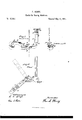
F. HENRY. Corde'r for Sewing Machines.
No. 42,657. Patented May 10, 1864.
I SCOZ'D' IL N PETERS. Plmtoiilhngmpher. Wasnmgwn. D. c.
UNIT D STATES PATENT OFFICE.
FRANK HENRY, OF BRIDGEPORT, CONNECTICUT.
IMPROVEMENT IN CORDERS FOR SEWING-MACHINES.
Specification forming part of Letters Patent No. 42,657, dated May 10 1864.
To all whom it may concern:
Beitknownthatl, FRANKHENRY, of Bridgeport, in the county of Fairfield, in the State of Connecticut, have invented a certain new and useful Improvement in Corders for use on Sewing-Machines; and I do hereby declare that the following is a full and exact description thereof;
The accompanying drawings form a part of thisjspecification and show the novel parts, with so much of the other parts as is necessary to exhibit their relation thereto. I prefer that general construction and arrangement of the parts of the machine (not represented) which is adopted in the machines known as Wheeler & Wilsons, but any other construction may serve nearly as well. My invention relates entirely to the parts represented.
Figure 1 is a front view of the presser-bar and its connections, showing my corder attached ready for use. The dark lines show the parts in the position maintained in cording very thick stuff. The red outlines indicate the position of the lower faces of some of the parts in cording thin material. Fig. 2 is a vertical section on line S S in Fig. 1; and Fig.3 is a plan view. The dark lines show the position of the parts in cording along astraight line. The red outline shows one of the positions it may assume in cording around curves or angles.
Similar letters of reference indicate like parts in all the figures.
To enable others skilled in the art to make and use my invention, I will proceed to describe its construction and operation by the aid of the drawings and of the letters of reference marked thereon.
A is a presser-bar, and B the resser-foot, mounted at the base of A, so as to rise and sink therewith. The presser-foot B is forked and grooved, as represented, in the same manner as in preparing it to receive the wellknown glass foot-piece. The presser-bar A is pressed down by a spring, (not represented,) and is adapted to slide vertically through the support C, and to be raised and held up at will against the tension of the spring by means of the cam-bar D. All these parts are well known and are arranged in the usual manner relatively to the needle and feed and to the other parts of the sewing-machine.
E is a piece of metal adapted to slide in and out in the presser-foot B. A portion of its under surface, 0, projects considerably below B, as represented.
G is a screw tapped into E, and forms a swiveling joint for the plate H and its connections I, I, J, and K. The latter, K, is a short tube, through which the cord M is delivered.
J is a piece to which K is brazed or otherwise firmly secured, andI I are screws tapped into H. These screws stand in a slot in the piece J and allow the position of H and J to be adjusted relatively each to the other. I lead the cord M through a slight guide, j, on its way from the spool (not represented) to the delivering-tube K. The ordinary notches are produced in the under face of the part which rests on the goods to guide the cord.
I have not deemed it necessary to represent the position of the goods to which the cord is to be sewed. It will be seen that my machine or device is adapted to perform all the functions of ordinary corders, and to allow all the modifications which may be required, while it differs from all before known in the fact that it involves the two important functions of moving vertically, as required, and also swiveling.
It is not necessary to the success of my invention that the part E and its attachments G H I J K be made at the same time or by the same maker as the other parts, B A, 860., to which these connect. 'I propose to construct my novel parts so as to be sold separately and adapted, like the construction represented, to be slid into any forked presser-foot which is adapted to receive the glass piece now in use; but I do not confine myself to such a form of the piece E. I can attach my device by making the whole presser-foot B removable, and removing it and attaching my piece E- by a screw, or otherwise, directly to the presser-bar A. In such case my piece E should be longer and differently shaped, but it would perform the same function as here represented Some of the advantages due to certain features or characteristics of my invention may be separately enumerated as follows:
First. By reason of my cord-guide K being I mounted on the presser-bar it rises and sinks therewith and adjusts itself to all thicknesses of goods; or, in other words, by reason of the delivering-tube K being supported upon the presser-bar, so as to rise and sink therewith, it
follows that it lies close to the cloth -plate when thin material is corded, and without any labor adjusts its elevation to every thickness of goods introduced.
Second. By reason of my cord-guide K being allowed to swivel on the pivot G, which is interposed between itself and the presserbar A, it can be readily turned out of the way in making corners or angles in the work. In other words, the delivering end of K being directly in the line of the axis of the screw-Gr, it follows that the swiveling part H I J K may be pushed forward or backward by the operator, so as to stand as indicated by the red outline, if required, in formingbends and corners in the work, and the cord will always be delivered aright and be secured by the stitches in the right position. I
Having now fully described my invention, what I claim as new therein,and desire to secure by Letters Patent, is as follows:
1. Attaching thecord-guide Kto the presserfoot or resser-bar of a sewing-machine, so that it shall rise and sink therewith to automatically adjust itself to the thickness of the goods being worked, substantially as herein set forth.
2. The employment of a swivel-joint, G, between the cord-guide K and the presser-foot or presser-bar, when the cord-guide K is carried vertically with each movement of the presser-bar, as herein set forth,
' FRANK HENRY.
WVitnesses:
R. E. HOUGH, CHAS. E. SHEL'roN.
Publications (1)
| Publication Number | Publication Date |
|---|---|
| US42657A true US42657A (en) | 1864-05-10 |
Family
ID=2112224
Family Applications (1)
| Application Number | Title | Priority Date | Filing Date |
|---|---|---|---|
| US42657D Expired - Lifetime US42657A (en) | Improvement in corders for sewing-machines |
Country Status (1)
| Country | Link |
|---|---|
| US (1) | US42657A (en) |
-
0
- US US42657D patent/US42657A/en not_active Expired - Lifetime
Similar Documents
| Publication | Publication Date | Title |
|---|---|---|
| US42657A (en) | Improvement in corders for sewing-machines | |
| US544751A (en) | Hemming-gage for sewing-machines | |
| US767301A (en) | Sewing-machine guide. | |
| US28776A (en) | Improvement in cordi ng-gu i des for sewing-machin es | |
| US886025A (en) | Welting attachment for sewing-machines. | |
| US246907A (en) | Presser-foot and guide for sewing-machines | |
| US930469A (en) | Open-welt guide. | |
| US134497A (en) | Improvement in presser-foot attachments for sewing-machines | |
| US233025A (en) | Ruffling attachment for sewing-machines | |
| US42989A (en) | beach cochkan | |
| US454010A (en) | Trimming mechanism for sewing-machines | |
| US460776A (en) | Welt-guide for sewing-machines | |
| US1129404A (en) | Presser device for sewing-machines. | |
| US125231A (en) | Improvement in ruffling attachments for sewing-machines | |
| US723608A (en) | Attachment-holder for sewing-machines. | |
| US350740A (en) | Combined adjustable presser-foot and gage for sewing-machines | |
| US43355A (en) | Jeptha a | |
| US288008A (en) | James f | |
| US115048A (en) | Improvement in cording attachments for sewing-machines | |
| US402584A (en) | Attachment-holder for sewing-machines | |
| US121366A (en) | Improvement in attachments for sewing-machines | |
| US976964A (en) | Binding mechanism for sewing-machines. | |
| US438796A (en) | Manufacturer s | |
| US689100A (en) | Tuck-folder for sewing-machines. | |
| US407572A (en) | campbell |