US4257654A - Filament wound bearing - Google Patents
Filament wound bearing Download PDFInfo
- Publication number
- US4257654A US4257654A US06/005,396 US539679A US4257654A US 4257654 A US4257654 A US 4257654A US 539679 A US539679 A US 539679A US 4257654 A US4257654 A US 4257654A
- Authority
- US
- United States
- Prior art keywords
- bearing
- antigalling
- bearing structure
- furnace
- rock bit
- Prior art date
- Legal status (The legal status is an assumption and is not a legal conclusion. Google has not performed a legal analysis and makes no representation as to the accuracy of the status listed.)
- Expired - Lifetime
Links
- 239000000463 material Substances 0.000 claims abstract description 41
- 239000011148 porous material Substances 0.000 claims abstract description 17
- 238000004804 winding Methods 0.000 claims abstract description 14
- 239000011435 rock Substances 0.000 claims description 13
- 229910052751 metal Inorganic materials 0.000 claims description 6
- 239000002184 metal Substances 0.000 claims description 6
- 239000000203 mixture Substances 0.000 claims description 3
- 229910001092 metal group alloy Inorganic materials 0.000 claims 1
- 238000009792 diffusion process Methods 0.000 abstract description 8
- 238000000280 densification Methods 0.000 abstract description 6
- 230000009471 action Effects 0.000 abstract description 4
- 238000000034 method Methods 0.000 description 12
- 230000008569 process Effects 0.000 description 7
- 239000011159 matrix material Substances 0.000 description 6
- 230000008595 infiltration Effects 0.000 description 5
- 238000001764 infiltration Methods 0.000 description 5
- 229910045601 alloy Inorganic materials 0.000 description 4
- 239000000956 alloy Substances 0.000 description 4
- 239000007788 liquid Substances 0.000 description 3
- 239000000314 lubricant Substances 0.000 description 3
- 238000010276 construction Methods 0.000 description 2
- 239000010949 copper Substances 0.000 description 2
- 238000003754 machining Methods 0.000 description 2
- 238000004519 manufacturing process Methods 0.000 description 2
- 238000012986 modification Methods 0.000 description 2
- 230000004048 modification Effects 0.000 description 2
- 230000035699 permeability Effects 0.000 description 2
- 238000005096 rolling process Methods 0.000 description 2
- UONOETXJSWQNOL-UHFFFAOYSA-N tungsten carbide Chemical compound [W+]#[C-] UONOETXJSWQNOL-UHFFFAOYSA-N 0.000 description 2
- RYGMFSIKBFXOCR-UHFFFAOYSA-N Copper Chemical compound [Cu] RYGMFSIKBFXOCR-UHFFFAOYSA-N 0.000 description 1
- 229910000760 Hardened steel Inorganic materials 0.000 description 1
- UFHFLCQGNIYNRP-UHFFFAOYSA-N Hydrogen Chemical compound [H][H] UFHFLCQGNIYNRP-UHFFFAOYSA-N 0.000 description 1
- 229910001347 Stellite Inorganic materials 0.000 description 1
- 239000004809 Teflon Substances 0.000 description 1
- 229920006362 Teflon® Polymers 0.000 description 1
- 229910001297 Zn alloy Inorganic materials 0.000 description 1
- 229910052787 antimony Inorganic materials 0.000 description 1
- WATWJIUSRGPENY-UHFFFAOYSA-N antimony atom Chemical compound [Sb] WATWJIUSRGPENY-UHFFFAOYSA-N 0.000 description 1
- 230000009286 beneficial effect Effects 0.000 description 1
- 230000015572 biosynthetic process Effects 0.000 description 1
- AHICWQREWHDHHF-UHFFFAOYSA-N chromium;cobalt;iron;manganese;methane;molybdenum;nickel;silicon;tungsten Chemical compound C.[Si].[Cr].[Mn].[Fe].[Co].[Ni].[Mo].[W] AHICWQREWHDHHF-UHFFFAOYSA-N 0.000 description 1
- 230000000295 complement effect Effects 0.000 description 1
- 238000009833 condensation Methods 0.000 description 1
- 230000005494 condensation Effects 0.000 description 1
- 229910052802 copper Inorganic materials 0.000 description 1
- TVZPLCNGKSPOJA-UHFFFAOYSA-N copper zinc Chemical compound [Cu].[Zn] TVZPLCNGKSPOJA-UHFFFAOYSA-N 0.000 description 1
- 238000005520 cutting process Methods 0.000 description 1
- 238000005553 drilling Methods 0.000 description 1
- 238000007667 floating Methods 0.000 description 1
- -1 for example Inorganic materials 0.000 description 1
- 238000005755 formation reaction Methods 0.000 description 1
- 239000007789 gas Substances 0.000 description 1
- 239000001257 hydrogen Substances 0.000 description 1
- 229910052739 hydrogen Inorganic materials 0.000 description 1
- 238000001802 infusion Methods 0.000 description 1
- 238000001746 injection moulding Methods 0.000 description 1
- 230000001050 lubricating effect Effects 0.000 description 1
- 230000013011 mating Effects 0.000 description 1
- 238000002844 melting Methods 0.000 description 1
- 230000008018 melting Effects 0.000 description 1
- 229910052982 molybdenum disulfide Inorganic materials 0.000 description 1
- 239000002245 particle Substances 0.000 description 1
- 239000000843 powder Substances 0.000 description 1
- 230000002265 prevention Effects 0.000 description 1
- 230000009467 reduction Effects 0.000 description 1
- 229910052709 silver Inorganic materials 0.000 description 1
- 239000004332 silver Substances 0.000 description 1
- 239000000126 substance Substances 0.000 description 1
- 238000003466 welding Methods 0.000 description 1
Images

Classifications
-
- E—FIXED CONSTRUCTIONS
- E21—EARTH OR ROCK DRILLING; MINING
- E21B—EARTH OR ROCK DRILLING; OBTAINING OIL, GAS, WATER, SOLUBLE OR MELTABLE MATERIALS OR A SLURRY OF MINERALS FROM WELLS
- E21B10/00—Drill bits
- E21B10/08—Roller bits
- E21B10/22—Roller bits characterised by bearing, lubrication or sealing details
-
- B—PERFORMING OPERATIONS; TRANSPORTING
- B65—CONVEYING; PACKING; STORING; HANDLING THIN OR FILAMENTARY MATERIAL
- B65H—HANDLING THIN OR FILAMENTARY MATERIAL, e.g. SHEETS, WEBS, CABLES
- B65H55/00—Wound packages of filamentary material
- B65H55/04—Wound packages of filamentary material characterised by method of winding
-
- F—MECHANICAL ENGINEERING; LIGHTING; HEATING; WEAPONS; BLASTING
- F16—ENGINEERING ELEMENTS AND UNITS; GENERAL MEASURES FOR PRODUCING AND MAINTAINING EFFECTIVE FUNCTIONING OF MACHINES OR INSTALLATIONS; THERMAL INSULATION IN GENERAL
- F16C—SHAFTS; FLEXIBLE SHAFTS; ELEMENTS OR CRANKSHAFT MECHANISMS; ROTARY BODIES OTHER THAN GEARING ELEMENTS; BEARINGS
- F16C33/00—Parts of bearings; Special methods for making bearings or parts thereof
- F16C33/02—Parts of sliding-contact bearings
- F16C33/04—Brasses; Bushes; Linings
- F16C33/06—Sliding surface mainly made of metal
- F16C33/14—Special methods of manufacture; Running-in
-
- F—MECHANICAL ENGINEERING; LIGHTING; HEATING; WEAPONS; BLASTING
- F16—ENGINEERING ELEMENTS AND UNITS; GENERAL MEASURES FOR PRODUCING AND MAINTAINING EFFECTIVE FUNCTIONING OF MACHINES OR INSTALLATIONS; THERMAL INSULATION IN GENERAL
- F16C—SHAFTS; FLEXIBLE SHAFTS; ELEMENTS OR CRANKSHAFT MECHANISMS; ROTARY BODIES OTHER THAN GEARING ELEMENTS; BEARINGS
- F16C33/00—Parts of bearings; Special methods for making bearings or parts thereof
- F16C33/02—Parts of sliding-contact bearings
- F16C33/04—Brasses; Bushes; Linings
- F16C33/26—Brasses; Bushes; Linings made from wire coils; made from a number of discs, rings, rods, or other members
-
- B—PERFORMING OPERATIONS; TRANSPORTING
- B65—CONVEYING; PACKING; STORING; HANDLING THIN OR FILAMENTARY MATERIAL
- B65H—HANDLING THIN OR FILAMENTARY MATERIAL, e.g. SHEETS, WEBS, CABLES
- B65H2701/00—Handled material; Storage means
- B65H2701/30—Handled filamentary material
- B65H2701/37—Tapes
-
- F—MECHANICAL ENGINEERING; LIGHTING; HEATING; WEAPONS; BLASTING
- F16—ENGINEERING ELEMENTS AND UNITS; GENERAL MEASURES FOR PRODUCING AND MAINTAINING EFFECTIVE FUNCTIONING OF MACHINES OR INSTALLATIONS; THERMAL INSULATION IN GENERAL
- F16C—SHAFTS; FLEXIBLE SHAFTS; ELEMENTS OR CRANKSHAFT MECHANISMS; ROTARY BODIES OTHER THAN GEARING ELEMENTS; BEARINGS
- F16C2220/00—Shaping
- F16C2220/60—Shaping by removing material, e.g. machining
- F16C2220/62—Shaping by removing material, e.g. machining by turning, boring, drilling
-
- F—MECHANICAL ENGINEERING; LIGHTING; HEATING; WEAPONS; BLASTING
- F16—ENGINEERING ELEMENTS AND UNITS; GENERAL MEASURES FOR PRODUCING AND MAINTAINING EFFECTIVE FUNCTIONING OF MACHINES OR INSTALLATIONS; THERMAL INSULATION IN GENERAL
- F16C—SHAFTS; FLEXIBLE SHAFTS; ELEMENTS OR CRANKSHAFT MECHANISMS; ROTARY BODIES OTHER THAN GEARING ELEMENTS; BEARINGS
- F16C2226/00—Joining parts; Fastening; Assembling or mounting parts
- F16C2226/10—Force connections, e.g. clamping
- F16C2226/12—Force connections, e.g. clamping by press-fit, e.g. plug-in
-
- F—MECHANICAL ENGINEERING; LIGHTING; HEATING; WEAPONS; BLASTING
- F16—ENGINEERING ELEMENTS AND UNITS; GENERAL MEASURES FOR PRODUCING AND MAINTAINING EFFECTIVE FUNCTIONING OF MACHINES OR INSTALLATIONS; THERMAL INSULATION IN GENERAL
- F16C—SHAFTS; FLEXIBLE SHAFTS; ELEMENTS OR CRANKSHAFT MECHANISMS; ROTARY BODIES OTHER THAN GEARING ELEMENTS; BEARINGS
- F16C2226/00—Joining parts; Fastening; Assembling or mounting parts
- F16C2226/30—Material joints
- F16C2226/36—Material joints by welding
-
- F—MECHANICAL ENGINEERING; LIGHTING; HEATING; WEAPONS; BLASTING
- F16—ENGINEERING ELEMENTS AND UNITS; GENERAL MEASURES FOR PRODUCING AND MAINTAINING EFFECTIVE FUNCTIONING OF MACHINES OR INSTALLATIONS; THERMAL INSULATION IN GENERAL
- F16C—SHAFTS; FLEXIBLE SHAFTS; ELEMENTS OR CRANKSHAFT MECHANISMS; ROTARY BODIES OTHER THAN GEARING ELEMENTS; BEARINGS
- F16C2352/00—Apparatus for drilling
-
- Y—GENERAL TAGGING OF NEW TECHNOLOGICAL DEVELOPMENTS; GENERAL TAGGING OF CROSS-SECTIONAL TECHNOLOGIES SPANNING OVER SEVERAL SECTIONS OF THE IPC; TECHNICAL SUBJECTS COVERED BY FORMER USPC CROSS-REFERENCE ART COLLECTIONS [XRACs] AND DIGESTS
- Y10—TECHNICAL SUBJECTS COVERED BY FORMER USPC
- Y10S—TECHNICAL SUBJECTS COVERED BY FORMER USPC CROSS-REFERENCE ART COLLECTIONS [XRACs] AND DIGESTS
- Y10S384/00—Bearings
- Y10S384/90—Cooling or heating
- Y10S384/902—Porous member
Definitions
- This invention relates to bearing structure, and more particularly to a filament wound bearing infiltrated with an antigalling material for improved bearing characteristics.
- bearings infiltrated with an antigalling material were made from a base of an alloy powder compressed into the shape of the desired bearing element thereby providing a porous matrix.
- the porous matrix was sintered and the antigalling material infiltrated into the porous structure.
- the infiltrated antigalling material was a copper or copper zinc alloy and in at least one such bearing structure the infiltrated material was silver.
- a reinfiltration of the bearing structure with antimony is employed to provide a harder surface.
- Other attempts to provide improved infiltrated bearing structures utilized Tungsten carbide particles in a high, temperature resistant, metal matrix.
- a bearing structure in accordance with the present invention includes the infiltration of an antigalling material into a wound core matrix.
- the core matrix is wound from a continous filament in a crisscrossed multilayered configuration to form a porous body. Pore size, pore spacing and permeability of the body may be varied by wire size selection, winding spacing and the number of crisscrossed layers.
- the density of the material is variable by rolling the body under a given pressure on a mandrel in a process for manufacturing the bearing structures of the present invention.
- the antigalling material infiltrated into the body structure includes any number of differing alloys and materials in addition to metallic and/or organic compositions.
- bearing structures of the present invention find extensive use in rotary rock bits, and the following description of the invention relates to rock bits, bearing structures as described are also useful as thrust bearings and in bearing configurations that include cylindical, flat washer and disc forms.
- the bearing structure of the present invention When utilized in a rotary rock bit the bearing structure of the present invention provides longer useful lifetimes for the bit. This improved performance is desirable since any extension of the useful life of the rotary bit results in a reduction of the number of times the drill string must be withdrawn to replace a failed bit.
- a wound filament bearing comprises a crisscrossed, multilayered porous, wire body wound into a selected configuration. Infiltrated into the porous areas of the body is an antigalling material with the antigalling material partially filling the porous areas.
- a bearing structure as described above is formed by first winding a filament into a porous multilayered, crisscrossed pattern of the desired configuration. Next, the filament pattern is densified by any one of several techniques to establish a desired pore density. Following densification the crossover areas of the crisscrossed pattern are bonded together. Next, the porous areas of the multilayered, crisscrossed pattern are infiltrated with the antigalling material.
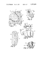
- FIG. 1 is a sectional view showing one cutter of a rotary cone rock bit including the bearing journal upon which a cone rotates with the bearing structure of the present invention between the cone inner surface and the journal surface;
- FIG. 2 is an enlarged sectional detail of the bearing structure of the present invention
- FIG. 3 is an enlarged section taken along the line 3--3 of FIG. 2;
- FIG. 4 schematically illustrates the winding step of the process of producing a bearing structure
- FIG. 5 is an enlarged view of the crisscrossed multilayered porous pattern produced by the winding step of FIG. 4;
- FIGS. 6-8 illustrate additional steps in the process of manufacturing bearing structure from the crisscrossed pattern of FIG. 5.
- FIG. 1 shows one cone, which is generally designated by the reference numeral 10, of a conventional three cone rotary rock bit.
- the bit body includes three substantially identical arms with one of the arms 12 partially illustrated in the figure.
- a rotary cone cutter 14 is rotatably positioned on a bearing pin 16 extending from the arm 12.
- the rotary cone cutter 14 includes customary metal inserts 18, as indicated, on its outer surface adapted to disintegrate the formations as the bit is rotated utilizing conventional drilling techniques.
- the metal inserts 18 are conventional and usually formed from Tungsten carbide although it is not uncommon that such metal inserts may be of a hardened steel.
- the bit body 12 and the bearing pin 16 are provided with a passageway through which ball bearings 20 are inserted to a ball race 22 in the cutter 14 and a complementary race 24 in the bearing pin.
- many rotary rock bits are provided with a lubricating system to provide a lubricant in the areas of the ball bearings 20 and other bearing surfaces between the rotary cone 14 and the bearing pin 16. Escape of lubricant from the bearing area within the cone and the prevention of entry of cuttings and other foreign materials from the outside is sealed off by a suitable seal, such as the O-ring 26, again all in a conventional arrangement.
- a main bearing 28 Positioned in the inner surface of the cutter 14 is a main bearing 28, which may be a free floating bearing, and positioned on the outer surface of the bearing pin 16 in mating contact with the bearing 28 is a hardened bearing surface 30.
- the hardened bearing surface 30 may be provided by welding and subsequent machining or by a ring insert pressed over the outer surface of the bearing pin 16.
- a thrust button 32 At the lower end of the journal 12 there is positioned in a cavity of the cutter 14 a thrust button 32 provided to resist the thrust forces generated between the end of the bearing pin 16 and the cone 14.
- a pilot bearing 34 Also provided on the bearing pin 16 is a pilot bearing 34 that is press fit into a cavity 36 of the cutter 14.
- the main bearing 28, the thrust button 32, and the pilot bearing 34 are all provided with hardened wear resistant bearing surfaces formed from a porous body and impregnated with a self-lubricant of an antigalling material.
- a bearing surface as will be described the useful lifetime of these bearings is extended, thereby extending the useful lifetime of the complete bit.
- Each of the bearings 28, 32 and 34 has improved wearing qualities when constructed from a filament that is wound with crossover sections that are diffusion bonded where porous areas are infiltrated with an antigalling material in accordance with the present invention.
- each of these bearing structures may be constructed from a wound filament the invention will be described with reference to the main bearing 28 having a cylindrical configuration, it being understood that the steps of the process to be described are equally applicable to the construction of bearings having a disc configuration.
- FIG. 4 there is shown apparatus for carrying out the first step, that is, winding a wire filament into a desired bearing structure configuration.
- the bearing structure 40 is formed by winding a fine wire filament 42 onto a mandrel 46 in a crisscross pattern 45, as shown in FIG. 5.
- the mandrel 46 is driven by a motor 48 connected to a controller 50 that controls rotational speed of the mandrel and the number of layers used to build up the bearing structure 40.
- a press roller 52 Prior to winding the wire filament 42 on the mandrel 46 it is flattened into a ribbon by means of a press roller 52 which also acts as a guide for directing the filament onto the mandrel 46 to develop the crisscross multilayered pattern 45 as shown in FIG. 5.
- the press roller 52 is positioned by means of a lead screw 54 driven by a motor 56 which is also coupled to the controller 50.
- the speed of the motor 56 is adjusted to the speed of the motor 48 to provide the desired crisscross pattern which in turn determines the pore size of the bearing structure 40.
- wire size, winding spacing and the number of layers of the bearing structure 40 are controlled to provide the desired pore size, pore spacing and permeability of the bearing structure.
- pore size and pore spacing are controlled so that the inside diameter and outside diameter of the bearing structure 40 have a fifteen percent (15%) density while the density of the supporting core may be as high as 87%.
- porosity of the bearing structure 40 which is a function of wire size and winding spacing, any given porosity (within a specific wire size) can be controlled from one layer to the next by means of the controller 50.
- the cylindrical bearing structure 40 is split and then flattened.
- the washer or disc shape is then cut from the flattened section of the bearing structure 40. Subsequent processing of such bearing configurations is similar to that to be described with reference to the cylindrical bearing structure 40 of FIG. 4.
- the bearing structure 40 following the step of winding the bearing structure 40 into the desired configuration, it is removed from the mandrel 46 and placed in a furnace 58 that is equipped with a resistance heater 60 and connected to a vacuum or hydrogen source by means of a controller 62.
- the controller 62 also connects to a switch 64 for controlling power to the resistance heater 60.
- both the atmosphere and temperature within the furnace 58 are controlled.
- the temperature is controlled to be compatible with the material of the wire filament 42 which may be any desired alloy, for example, Stellite 190, BeCu, 4815, or 400 SST as representative examples.
- the temperature within the furnace 58 is raised to a point where the crossover points 45a of the flattened filament, see FIG. 5, are diffusion bonded.
- the final density of the bearing structure 40 is achieved by rolling between mandrels 66 and 68.
- a desired pressure is developed on the bearing structure 40 by means of adjustments 70 and 72, shown schematically in FIG. 7.
- the mandrel 68 is rotated on a shaft 74 by means of a motor 76 that rotates at a controlled speed for developing the desired densification of the bearing structure 40.
- the bearing structure 40 is rotated on the mandrel 68 until a desired density is achieved at the pressure applied to the mandrel 66 by means of the adjustments 70 and 72.
- the desired densification of the structure may also be achieved by rotary swagging or roller burnishing or a combination of these three processes.
- the bearing structure 40 is again returned to the furnace 58 for a second diffusion bonding step to further expand the bonded areas, that is, the crossover areas 45a as shown in FIG. 5.
- the resulting structure is composed of flat wound strips bonded together in a form to provide a load supporting core.
- the bearing structure 40 is now ready for infiltration with an antigalling material.
- Infiltration of an antigalling material into the bearing structure 40 may be accomplished by a number of different techniques; however, the most direct method consists of placing the filament wound structure in a crucible along with the antigalling material to be infiltrated. The crucible and its contents are then placed in a furnace, the temperature is raised to a value above the liquid point of the antigalling material and a vacuum is applied to the furnace. When the infiltrated antigalling material is in a liquid state, capillary action draws the infiltrate to fill the pores of the bearing structure 40.
- the furnace 58 for carrying out the step of infiltrating the bearing structure 40 with an antigalling material.
- the bearing structure 40 is placed in a crucible 78 filled with the infiltrate material.
- the switch 64 is closed to apply power to the resistance heater 60 and the temperature within the furnace 58 is raised to a level above the melting point of the infiltrate material.
- the controller 62 opens the interior of the furnace 58 to a source of vacuum thereby evacuating the furnace.
- the infiltrate antigalling material When the infiltrate antigalling material is in a liquid state in a vacuum atmosphere the pores of the bearing structure 40 are filled by means of capillary action. The capillary action continues until the entire structure has been filled with the infiltrate material and the vacuum is then released and the furnace allowed to cool and the bearing structure is removed. At this point, the bearing structure has the desired load supporting characteristic and is infiltrated with a material to provide improved bearing performance.
- the physical and chemical properties of the infiltrate in the wound filament bearing structure thus becomes a system designed to operate efficiently on a bearing surface to yield improved performance.
- the infiltrate antigalling material is any one of a number of differing alloys and materials, metallic and/or organic compositions.
- examples of infiltrate material include Ampco-trode 300, Ag 85%+Mn 15%, Be+Cu, Teflon+MOS 2 , as representative examples.
- infiltrate process need not be limited to the vacuum melt method of FIG. 8.
- Other infiltration processes include injection molding and gas infusion condensation.
- the infiltrated wound bearing structure may be further heat treated or subject to additional processing, such as machining, to achieve the desired inside diameter and outside diameter dimensions.
- additional processing is not part of the present invention and are steps that are usually required in conventional bearing construction.
Landscapes
- Engineering & Computer Science (AREA)
- General Engineering & Computer Science (AREA)
- Mechanical Engineering (AREA)
- Life Sciences & Earth Sciences (AREA)
- Geology (AREA)
- Mining & Mineral Resources (AREA)
- Physics & Mathematics (AREA)
- Environmental & Geological Engineering (AREA)
- Fluid Mechanics (AREA)
- General Life Sciences & Earth Sciences (AREA)
- Geochemistry & Mineralogy (AREA)
- Sliding-Contact Bearings (AREA)
Abstract
Description
Claims (7)
Priority Applications (1)
| Application Number | Priority Date | Filing Date | Title |
|---|---|---|---|
| US06/005,396 US4257654A (en) | 1979-01-22 | 1979-01-22 | Filament wound bearing |
Applications Claiming Priority (1)
| Application Number | Priority Date | Filing Date | Title |
|---|---|---|---|
| US06/005,396 US4257654A (en) | 1979-01-22 | 1979-01-22 | Filament wound bearing |
Publications (1)
| Publication Number | Publication Date |
|---|---|
| US4257654A true US4257654A (en) | 1981-03-24 |
Family
ID=21715638
Family Applications (1)
| Application Number | Title | Priority Date | Filing Date |
|---|---|---|---|
| US06/005,396 Expired - Lifetime US4257654A (en) | 1979-01-22 | 1979-01-22 | Filament wound bearing |
Country Status (1)
| Country | Link |
|---|---|
| US (1) | US4257654A (en) |
Cited By (5)
| Publication number | Priority date | Publication date | Assignee | Title |
|---|---|---|---|---|
| US4400099A (en) * | 1981-02-06 | 1983-08-23 | Miba Gleitlager Aktiengesellschaft | Sliding surface bearing for heavy loads |
| US4514098A (en) * | 1982-09-01 | 1985-04-30 | Dresser Industries, Inc. | Wound wire bearing |
| US4618269A (en) * | 1985-09-18 | 1986-10-21 | Reed Tool Company | Hardened bearing surface and method of forming same |
| US20050196082A1 (en) * | 2004-01-29 | 2005-09-08 | Albert Asfour | Bearing with integral seal |
| EP2065550A1 (en) * | 2004-12-03 | 2009-06-03 | Baker Hughes Incorporated | Micropore engagement surface for earth boring bit |
-
1979
- 1979-01-22 US US06/005,396 patent/US4257654A/en not_active Expired - Lifetime
Non-Patent Citations (1)
| Title |
|---|
| Facet Poroloy pamphlet (prior art-no date). |
Cited By (5)
| Publication number | Priority date | Publication date | Assignee | Title |
|---|---|---|---|---|
| US4400099A (en) * | 1981-02-06 | 1983-08-23 | Miba Gleitlager Aktiengesellschaft | Sliding surface bearing for heavy loads |
| US4514098A (en) * | 1982-09-01 | 1985-04-30 | Dresser Industries, Inc. | Wound wire bearing |
| US4618269A (en) * | 1985-09-18 | 1986-10-21 | Reed Tool Company | Hardened bearing surface and method of forming same |
| US20050196082A1 (en) * | 2004-01-29 | 2005-09-08 | Albert Asfour | Bearing with integral seal |
| EP2065550A1 (en) * | 2004-12-03 | 2009-06-03 | Baker Hughes Incorporated | Micropore engagement surface for earth boring bit |
Similar Documents
| Publication | Publication Date | Title |
|---|---|---|
| US4105263A (en) | Journal and pilot bearings with alternating surface areas of wear resistant and anti-galling materials | |
| US3235316A (en) | Journal bearing with alternating surface areas of wear resistant and antigalling materials | |
| CA1319930C (en) | Roller drill bit having radial-thrust pilot bushing incorporating anti-galling material | |
| US9808910B2 (en) | Polycrystalline diamond compacts | |
| EP0643792B1 (en) | Rolling cone bit with wear resistant insert | |
| EP0169718B1 (en) | Conical cutters for drill bits and processes to produce same | |
| CA1170028A (en) | Method of fabrication of rock bit inserts | |
| US8397841B1 (en) | Drill bit with cutting elements having functionally engineered wear surface | |
| US6725953B2 (en) | Drill bit having diamond impregnated inserts primary cutting structure | |
| US5284394A (en) | Ball and roller bearings and bearing components | |
| US20140069022A1 (en) | Methods of fabricating polycrystalline diamond compacts | |
| CN101542067A (en) | Earth-boring rotary drill bits including bit bodies having boron carbide particles in aluminum or aluminum-based alloy matrix materials, and methods for forming such bits | |
| US3784264A (en) | Earth boring bit bearing system having a pitted bearing surface | |
| JPH0321716B2 (en) | ||
| US4257654A (en) | Filament wound bearing | |
| CA2865794A1 (en) | A method for making a bearing component, a bearing component, a down hole device and a down hole bearing assembly | |
| GB2054064A (en) | Bearings and bearing blocks for use with deep-drilling bits, tools or devices operable in a borehole | |
| CA1123822A (en) | Insert for tool wear surfaces and method of manufacture | |
| US4207658A (en) | Journal and pilot bearings with alternating surface areas of wear resistant and anti-galling materials | |
| US4172395A (en) | Method of manufacturing a rotary rock bit | |
| RU2067152C1 (en) | Carbide insert for use in drilling tool | |
| US4499642A (en) | Composite bearing | |
| US4787129A (en) | Metal of manufacturing a composite journal bushing | |
| CA1107716A (en) | Earth boring bit with gridded ferrous bearing surface | |
| US4819517A (en) | Selected bearing couple for a rock bit journal and method for making same |
Legal Events
| Date | Code | Title | Description |
|---|---|---|---|
| AS | Assignment |
Owner name: GENERAL ELECTRIC CAPITAL CORPORATION, GEORGIA Free format text: SECURITY INTEREST;ASSIGNOR:VAREL MANUFACTURING COMPANY;REEL/FRAME:008222/0771 Effective date: 19970116 |
|
| AS | Assignment |
Owner name: BANK OF SCOTLAND, NEW YORK Free format text: ASSIGNMENT OF ASSIGNORS INTEREST;ASSIGNOR:VAREL INTERNATIONAL, INC.;REEL/FRAME:009350/0978 Effective date: 19980630 |
|
| AS | Assignment |
Owner name: VAREL INTERNATIONAL, INC., TEXAS Free format text: CHANGE OF NAME;ASSIGNOR:VAREL MANUFACTURING COMPANY;REEL/FRAME:009638/0193 Effective date: 19980102 |
|
| AS | Assignment |
Owner name: VAREL INTERNATIONAL, LTD, TEXAS Free format text: RELEASE OF ASSIGNMENT;ASSIGNOR:THE GOVERNOR AND COMPANY OF THE BANK OF SCOTLAND, AS ADMINISTRATIVE AGENT;REEL/FRAME:016097/0250 Effective date: 20050601 |