US4256079A - Wire blades - Google Patents
Wire blades Download PDFInfo
- Publication number
- US4256079A US4256079A US06/032,251 US3225179A US4256079A US 4256079 A US4256079 A US 4256079A US 3225179 A US3225179 A US 3225179A US 4256079 A US4256079 A US 4256079A
- Authority
- US
- United States
- Prior art keywords
- wire
- supports
- wires
- roll
- clamp
- Prior art date
- Legal status (The legal status is an assumption and is not a legal conclusion. Google has not performed a legal analysis and makes no representation as to the accuracy of the status listed.)
- Expired - Lifetime
Links
- 239000000463 material Substances 0.000 claims description 3
- 238000005520 cutting process Methods 0.000 abstract description 8
- RYGMFSIKBFXOCR-UHFFFAOYSA-N Copper Chemical compound [Cu] RYGMFSIKBFXOCR-UHFFFAOYSA-N 0.000 description 4
- 229910052802 copper Inorganic materials 0.000 description 4
- 239000010949 copper Substances 0.000 description 4
- 239000002184 metal Substances 0.000 description 3
- 229910052751 metal Inorganic materials 0.000 description 3
- 235000012431 wafers Nutrition 0.000 description 3
- 238000004804 winding Methods 0.000 description 3
- 238000005253 cladding Methods 0.000 description 2
- 229910000831 Steel Inorganic materials 0.000 description 1
- 230000004323 axial length Effects 0.000 description 1
- 239000010453 quartz Substances 0.000 description 1
- 229910052594 sapphire Inorganic materials 0.000 description 1
- 239000010980 sapphire Substances 0.000 description 1
- 229910052710 silicon Inorganic materials 0.000 description 1
- 239000010703 silicon Substances 0.000 description 1
- VYPSYNLAJGMNEJ-UHFFFAOYSA-N silicon dioxide Inorganic materials O=[Si]=O VYPSYNLAJGMNEJ-UHFFFAOYSA-N 0.000 description 1
- 239000010959 steel Substances 0.000 description 1
- 230000007704 transition Effects 0.000 description 1
Images
Classifications
-
- B—PERFORMING OPERATIONS; TRANSPORTING
- B65—CONVEYING; PACKING; STORING; HANDLING THIN OR FILAMENTARY MATERIAL
- B65H—HANDLING THIN OR FILAMENTARY MATERIAL, e.g. SHEETS, WEBS, CABLES
- B65H54/00—Winding, coiling, or depositing filamentary material
- B65H54/02—Winding and traversing material on to reels, bobbins, tubes, or like package cores or formers
- B65H54/10—Winding and traversing material on to reels, bobbins, tubes, or like package cores or formers for making packages of specified shapes or on specified types of bobbins, tubes, cores, or formers
- B65H54/106—Manual or other small, compact or portable winding devices for forming packages for different purposes
-
- B—PERFORMING OPERATIONS; TRANSPORTING
- B23—MACHINE TOOLS; METAL-WORKING NOT OTHERWISE PROVIDED FOR
- B23P—METAL-WORKING NOT OTHERWISE PROVIDED FOR; COMBINED OPERATIONS; UNIVERSAL MACHINE TOOLS
- B23P15/00—Making specific metal objects by operations not covered by a single other subclass or a group in this subclass
- B23P15/28—Making specific metal objects by operations not covered by a single other subclass or a group in this subclass cutting tools
-
- B—PERFORMING OPERATIONS; TRANSPORTING
- B28—WORKING CEMENT, CLAY, OR STONE
- B28D—WORKING STONE OR STONE-LIKE MATERIALS
- B28D5/00—Fine working of gems, jewels, crystals, e.g. of semiconductor material; apparatus or devices therefor
- B28D5/04—Fine working of gems, jewels, crystals, e.g. of semiconductor material; apparatus or devices therefor by tools other than rotary type, e.g. reciprocating tools
- B28D5/042—Fine working of gems, jewels, crystals, e.g. of semiconductor material; apparatus or devices therefor by tools other than rotary type, e.g. reciprocating tools by cutting with blades or wires mounted in a reciprocating frame
-
- B—PERFORMING OPERATIONS; TRANSPORTING
- B28—WORKING CEMENT, CLAY, OR STONE
- B28D—WORKING STONE OR STONE-LIKE MATERIALS
- B28D5/00—Fine working of gems, jewels, crystals, e.g. of semiconductor material; apparatus or devices therefor
- B28D5/04—Fine working of gems, jewels, crystals, e.g. of semiconductor material; apparatus or devices therefor by tools other than rotary type, e.g. reciprocating tools
- B28D5/045—Fine working of gems, jewels, crystals, e.g. of semiconductor material; apparatus or devices therefor by tools other than rotary type, e.g. reciprocating tools by cutting with wires or closed-loop blades
-
- B—PERFORMING OPERATIONS; TRANSPORTING
- B65—CONVEYING; PACKING; STORING; HANDLING THIN OR FILAMENTARY MATERIAL
- B65H—HANDLING THIN OR FILAMENTARY MATERIAL, e.g. SHEETS, WEBS, CABLES
- B65H59/00—Adjusting or controlling tension in filamentary material, e.g. for preventing snarling; Applications of tension indicators
- B65H59/02—Adjusting or controlling tension in filamentary material, e.g. for preventing snarling; Applications of tension indicators by regulating delivery of material from supply package
- B65H59/04—Adjusting or controlling tension in filamentary material, e.g. for preventing snarling; Applications of tension indicators by regulating delivery of material from supply package by devices acting on package or support
-
- B—PERFORMING OPERATIONS; TRANSPORTING
- B65—CONVEYING; PACKING; STORING; HANDLING THIN OR FILAMENTARY MATERIAL
- B65H—HANDLING THIN OR FILAMENTARY MATERIAL, e.g. SHEETS, WEBS, CABLES
- B65H2701/00—Handled material; Storage means
- B65H2701/30—Handled filamentary material
- B65H2701/35—Ropes, lines
- B65H2701/354—Cutting lines, e.g. for grass cutting
-
- Y—GENERAL TAGGING OF NEW TECHNOLOGICAL DEVELOPMENTS; GENERAL TAGGING OF CROSS-SECTIONAL TECHNOLOGIES SPANNING OVER SEVERAL SECTIONS OF THE IPC; TECHNICAL SUBJECTS COVERED BY FORMER USPC CROSS-REFERENCE ART COLLECTIONS [XRACs] AND DIGESTS
- Y10—TECHNICAL SUBJECTS COVERED BY FORMER USPC
- Y10S—TECHNICAL SUBJECTS COVERED BY FORMER USPC CROSS-REFERENCE ART COLLECTIONS [XRACs] AND DIGESTS
- Y10S83/00—Cutting
- Y10S83/929—Particular nature of work or product
- Y10S83/949—Continuous or wound supply
- Y10S83/95—Strandlike
Definitions
- This invention relates to wire blades for cutting hard materials into wafers.
- wire blades can be clamped in a blade pack at equal tension and with equal spacing between each wire if the pack is made by winding wire in a helix around a generally cylindrical roll while maintaining a constant drag on the wire, clamping the wire wrapped on the roll between two sets of clamps extending axially of the roll, and spaced circumferentially from each other, and then cutting the wire portions between the sets of clamps.
- the roll is exteriorly threaded (pitch less than 0.02 in.), the roll translates axially a distance equal to its pitch during each roll rotation as the wire is wound onto it, and each set of clamps is mounted in a milled axial slot in the roll periphery.
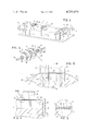
- FIG. 1 is a perspective, somewhat simplified, view of preferred wire pack winding apparatus
- FIG. 2 is a perspective view of the slip clutch and supply spool of the system of FIG. 1;
- FIG. 3 is a sectional end view of the roll and wire clamp of the system of FIG. 1;
- FIG. 4 is a sectional view taken at 4--4 of FIG. 3;
- FIG. 5 is an enlarged view of a portion of FIG. 4.
- an exteriorly threaded roll 10 is fixed on coaxial threaded shaft 12 which itself is threaded through a pair of spaced supports 14, 16.
- An offset crank handle 18 is provided at one end of shaft 12.
- the helical threads of roll 10 and shaft 12 both have the same pitch, 1/64 in., so that the roll will translate axially one thread per revolution of shaft 12.
- a spool 20 of wire 22 (copper clad wire having a steel core 0.005 l in. diameter and 0.0015 in. thick cladding) is mounted on a shaft 26 journaled in support 28 parallel to and about 18 in. from shaft 12.
- a small (1/60 hp.) geared-down electric motor 30 mounted on support 28 drives shaft in counterclockwise (as viewed in FIG. 1) at a speed of about 1 rpm.
- Spool 20 itself is freely rotatable relative to shaft 26.
- An adjustable slip assembly couples shaft 26 and spool 20 providing a torque tending to rotate spool (as shown in FIG. 1) counterclockwise. As shown in FIG.
- the clutch assembly comprises, on each side of spool 20, a pair of discs 32 and a felt clutch pad 34 between and engaging the facing surfaces of each pair of discs.
- the pair of discs 32 and intermediate pad 34 nearest motor 30 are held axially in place by nuts 36.
- a helical spring 38 surrounds the shaft on the other side of spool 20 and is forced against the outer one of the other pair of discs 32 by an axially adjustable disc 40 and adjusting nut 42.
- a guide pulley 44 is mounted for rotation on a shaft 46, parallel to shafts 12 and 26 and journalled in support 48.
- Pulley 44 has a V-shaped groove the top of the base of which is positioned slightly above a straight line extending from the top of the wire wound on spool 20 to the top of roll 10.
- wire extending from spool 20 over pulley 44 to roll 10 is deflected slightly upwardly, and positively positioned by guide pulley 44.
- the exterior surface 50 or roll 10 is threaded, 64 threads per inch, along its entire 6 in. length.
- Each thread 52 has a 60° included angle and a major diameter of 5.204 in.
- a 1.500 in. wide, 0.500 in. deep at its side edges axial slot 54 is milled into the outside of roll 10.
- Mounted in slot 54 are two clamps bases 56, 57, each 1/2 in. wide and about 0.49 in. (as shown in FIGS. 3 and 5, the 0.500 in. slot depth less the distance from the exterior of the roll to the bottom of wire wound in the threads) high and extending the full axial length of roll 10.
- a back-up plate 58 which provides a reference permitting the clamp bases to be exactly positioned axially relative to each other.
- Clamp bases 56, 57 are held in place in slot 54 by cap screws 60, one at each end of each base, extending from counterbores in the clamps into threaded holes in roll 10.
- a flat, thin strip of deformable metal 64, typically copper, is placed on top of the wire turns on each clamp base 56, 57, between the wire turns and the flat bottom clamping surfaces of clamp tops 62, 63.
- clamp tops 62, 63 are each about 1/2 in. wide and 1/2 high, and are about 1 inch shorter than clamp bases so that cap screws 60 are accessible when the clamp tops are in position on the clamp bases.
- Cap screws 66 one at each of each clamp to 62, 63, extend through the clamp tops into respective threaded holes in clamp bases 56, 57. When the screws are tightened, the clamp tops are drawn tightly down onto the clamp bases, firmly holding the wires therebetween.
- the deformable metal strips 64 assure positive gripping.
- clamp bases 56, 57 are bolted in place in slot 54, and crank 18 is then turned (counterclockwise as shown in FIG. 1) until the top of the thread 52 on which winding is to begin lies in a plane perpendicular to the axes of shafts 12 and 46 and passing through the apex of the V-shaped base of pulley 44.
- Shaft 12 is then locked in place, and wire from spool 20 is fed from it, over pulley 44, into the aligned thread 52, and into slot 54 between clamp bases 56, 57.
- the end of the wire is there held by a set screw 70 in the side of clamp base 56.
- Motor 30 is then actuated, causing shaft 26 to rotate counterclockwise and, through the adjustable slip clutch assembly, exert a counterclockwise torque on spool 20 and a corresponding drag (typically of about one pound on wire 22). Shaft 12 is then unlocked and the wire, with the drag being exerted on it, is then wound on the spool by turning crank 18 clockwise (as shown in FIG. 1).
- the result is a wire pack including plurality of wires (typically about 250 wires) of the same length (about 15 in.) and spaced exactly 1/64 in. from each other, tightly held by and extending between the sets of clamps.
- the wire pack may then be mounted in a cutting machine and the wires tensioned in the usual manner.
- Metal strip 64 is unnecessary when the copper or other soft cladding of wire 22 is itself sufficiently deformable to insure the necessary positive grip between the wire and clamps.
- the roll 10 on which the wire 22 is wrapped does not necessarily have to be cylindrical or threaded, especially if close wire spacing is used. If, for example, a wire alignment fixture is provided adjacent clamp bases 56, 57 (e.g., between or at one side of the clamps) to position the wire as it crosses over the clamp bases, or the clamp bases themselves are slotted for alignment, threads 52 may be omitted and a smooth cylindrical roll used.
- the wire 22 may be purchased already charged with abrasive, charged after mounting in the cutting machine in the manner disclosed in U.S. Pat. No. 4,092,972, or used in a three-body cutting process as also described in said Patent.
Landscapes
- Engineering & Computer Science (AREA)
- Mechanical Engineering (AREA)
- Finish Polishing, Edge Sharpening, And Grinding By Specific Grinding Devices (AREA)
Abstract
Description
Claims (4)
Priority Applications (2)
| Application Number | Priority Date | Filing Date | Title |
|---|---|---|---|
| US06/032,251 US4256079A (en) | 1978-06-22 | 1979-04-23 | Wire blades |
| US06/174,452 US4349178A (en) | 1979-04-23 | 1980-08-01 | Wire blades |
Applications Claiming Priority (2)
| Application Number | Priority Date | Filing Date | Title |
|---|---|---|---|
| US05/917,918 US4178670A (en) | 1978-06-22 | 1978-06-22 | Process of forming a wire pack |
| US06/032,251 US4256079A (en) | 1978-06-22 | 1979-04-23 | Wire blades |
Related Parent Applications (1)
| Application Number | Title | Priority Date | Filing Date |
|---|---|---|---|
| US05/917,918 Division US4178670A (en) | 1978-06-22 | 1978-06-22 | Process of forming a wire pack |
Related Child Applications (1)
| Application Number | Title | Priority Date | Filing Date |
|---|---|---|---|
| US06/174,452 Division US4349178A (en) | 1979-04-23 | 1980-08-01 | Wire blades |
Publications (1)
| Publication Number | Publication Date |
|---|---|
| US4256079A true US4256079A (en) | 1981-03-17 |
Family
ID=26708179
Family Applications (1)
| Application Number | Title | Priority Date | Filing Date |
|---|---|---|---|
| US06/032,251 Expired - Lifetime US4256079A (en) | 1978-06-22 | 1979-04-23 | Wire blades |
Country Status (1)
| Country | Link |
|---|---|
| US (1) | US4256079A (en) |
Cited By (5)
| Publication number | Priority date | Publication date | Assignee | Title |
|---|---|---|---|---|
| US20040200332A1 (en) * | 2003-04-09 | 2004-10-14 | Chen Hsi Tang | Cable receiving or storing device |
| US20070158654A1 (en) * | 2006-01-03 | 2007-07-12 | Kholodenko Arnold V | Apparatus for fabricating large-surface area polycrystalline silicon sheets for solar cell application |
| US20090044672A1 (en) * | 2007-08-16 | 2009-02-19 | Delta Electronics Power (Dongguan) Co., Ltd. | Apparatus for Forming Tin Flakes |
| WO2015039524A1 (en) * | 2013-09-18 | 2015-03-26 | 凡登(常州)新型金属材料技术有限公司 | Metal wire for cutting free abrasive, and manufacturing device and method for same |
| CN113335997A (en) * | 2021-06-09 | 2021-09-03 | 浙江福立分析仪器股份有限公司 | Automatic winding device and rapid winding method for multilayer quantitative ring |
Citations (11)
| Publication number | Priority date | Publication date | Assignee | Title |
|---|---|---|---|---|
| US590129A (en) * | 1897-09-14 | Vegetable-cutter | ||
| US2623550A (en) * | 1948-12-20 | 1952-12-30 | Pierre Dreyfuss Baumann | Method of making split rings |
| US3079908A (en) * | 1960-11-22 | 1963-03-05 | Norton Co | Multiple blade power hacksaw |
| US3126616A (en) * | 1962-10-10 | 1964-03-31 | figure | |
| US3168087A (en) * | 1962-05-14 | 1965-02-02 | Norton Co | Wafering machine |
| US3226803A (en) * | 1961-08-21 | 1966-01-04 | Rca Corp | Method of producing frames for grid electrodes |
| US3263670A (en) * | 1962-05-14 | 1966-08-02 | Norton Co | Wafering machine |
| US3326071A (en) * | 1965-03-19 | 1967-06-20 | Norton Co | Dicing machine |
| US3425122A (en) * | 1964-02-01 | 1969-02-04 | Telefunken Patent | Method of making an electrical switch sub-assembly |
| US3435815A (en) * | 1966-07-15 | 1969-04-01 | Micro Tech Mfg Inc | Wafer dicer |
| US4092972A (en) * | 1977-02-11 | 1978-06-06 | Crystal Systems, Inc. | Process of cutting wafers |
-
1979
- 1979-04-23 US US06/032,251 patent/US4256079A/en not_active Expired - Lifetime
Patent Citations (11)
| Publication number | Priority date | Publication date | Assignee | Title |
|---|---|---|---|---|
| US590129A (en) * | 1897-09-14 | Vegetable-cutter | ||
| US2623550A (en) * | 1948-12-20 | 1952-12-30 | Pierre Dreyfuss Baumann | Method of making split rings |
| US3079908A (en) * | 1960-11-22 | 1963-03-05 | Norton Co | Multiple blade power hacksaw |
| US3226803A (en) * | 1961-08-21 | 1966-01-04 | Rca Corp | Method of producing frames for grid electrodes |
| US3168087A (en) * | 1962-05-14 | 1965-02-02 | Norton Co | Wafering machine |
| US3263670A (en) * | 1962-05-14 | 1966-08-02 | Norton Co | Wafering machine |
| US3126616A (en) * | 1962-10-10 | 1964-03-31 | figure | |
| US3425122A (en) * | 1964-02-01 | 1969-02-04 | Telefunken Patent | Method of making an electrical switch sub-assembly |
| US3326071A (en) * | 1965-03-19 | 1967-06-20 | Norton Co | Dicing machine |
| US3435815A (en) * | 1966-07-15 | 1969-04-01 | Micro Tech Mfg Inc | Wafer dicer |
| US4092972A (en) * | 1977-02-11 | 1978-06-06 | Crystal Systems, Inc. | Process of cutting wafers |
Non-Patent Citations (1)
| Title |
|---|
| R.C.A., TN 829, "An Improved Cutting-Wire Fixture for Semiconductor Dicing Saw", Apr. 18, 1969. * |
Cited By (6)
| Publication number | Priority date | Publication date | Assignee | Title |
|---|---|---|---|---|
| US20040200332A1 (en) * | 2003-04-09 | 2004-10-14 | Chen Hsi Tang | Cable receiving or storing device |
| US20070158654A1 (en) * | 2006-01-03 | 2007-07-12 | Kholodenko Arnold V | Apparatus for fabricating large-surface area polycrystalline silicon sheets for solar cell application |
| US7572334B2 (en) | 2006-01-03 | 2009-08-11 | Applied Materials, Inc. | Apparatus for fabricating large-surface area polycrystalline silicon sheets for solar cell application |
| US20090044672A1 (en) * | 2007-08-16 | 2009-02-19 | Delta Electronics Power (Dongguan) Co., Ltd. | Apparatus for Forming Tin Flakes |
| WO2015039524A1 (en) * | 2013-09-18 | 2015-03-26 | 凡登(常州)新型金属材料技术有限公司 | Metal wire for cutting free abrasive, and manufacturing device and method for same |
| CN113335997A (en) * | 2021-06-09 | 2021-09-03 | 浙江福立分析仪器股份有限公司 | Automatic winding device and rapid winding method for multilayer quantitative ring |
Similar Documents
| Publication | Publication Date | Title |
|---|---|---|
| US4178670A (en) | Process of forming a wire pack | |
| EP1371467B1 (en) | Wire saw and method of slicing a cylindrical workpiece | |
| US4256079A (en) | Wire blades | |
| US5457877A (en) | Apparatus and method for cutting through cable sheathings | |
| US3789594A (en) | Wrapping apparatus | |
| US4349178A (en) | Wire blades | |
| CA1120382A (en) | Wire blades | |
| GB2025709A (en) | Wire stripper | |
| US3042329A (en) | Ligature measuring device | |
| US3314321A (en) | Apparatus for slitting ribbon cables | |
| US4500047A (en) | Spool adaptor | |
| JPH03196992A (en) | Slitter for cutting cut-work, e.g. tape, sheet, etc. | |
| JPH0818243B2 (en) | Wire winding device for wire tensioning mechanism | |
| JPS5831391Y2 (en) | Coil Kenkaiyo Hojig | |
| JPS63186B2 (en) | ||
| JPS58179609A (en) | Cutter for thin piece | |
| JP3256155B2 (en) | Wire saw | |
| JPH0839419A (en) | Mounting structure of wire reel on wire saw | |
| WO1984004856A1 (en) | Cutting device for stripping layers of cables and similar products | |
| CN223836778U (en) | A winding device for winding wire | |
| US20250149870A1 (en) | Highly efficient wire stripping machine | |
| JPS635395Y2 (en) | ||
| EP0333072A2 (en) | Bar guiding device for bar feeders of machine tools | |
| JPH11147218A (en) | Wire saw | |
| JPS635394Y2 (en) |
Legal Events
| Date | Code | Title | Description |
|---|---|---|---|
| AS | Assignment |
Owner name: CRYSTAL SYSTEMS, INC., A DE CORP. Free format text: MERGER;ASSIGNORS:CRYSTAL SYSTEMS, INC.;CRYSTAL SYSTEMS, INC., A DE CORP.;REEL/FRAME:004258/0055 Effective date: 19840110 |
|
| AS | Assignment |
Owner name: MIDDLESEX SAVINGS BANK, MASSACHUSETTS Free format text: SECURITY AGREEMENT;ASSIGNOR:CRYSTAL SYSTEMS, INC.;REEL/FRAME:023731/0162 Effective date: 20090501 |
|
| AS | Assignment |
Owner name: CRYSTAL SYSTEMS, INC., MASSACHUSETTS Free format text: RELEASE BY SECURED PARTY;ASSIGNOR:MIDDLESEX SAVINGS BANK;REEL/FRAME:025345/0404 Effective date: 20100805 |
|
| AS | Assignment |
Owner name: GT CRYSTAL SYSTEMS, LLC, MASSACHUSETTS Free format text: MERGER;ASSIGNOR:CRYSTAL SYSTEMS, INC.;REEL/FRAME:025468/0600 Effective date: 20100729 |