US4248492A - Electrical connector assembly having means for shielding against electromagnetic interference - Google Patents
Electrical connector assembly having means for shielding against electromagnetic interference Download PDFInfo
- Publication number
- US4248492A US4248492A US06/071,461 US7146179A US4248492A US 4248492 A US4248492 A US 4248492A US 7146179 A US7146179 A US 7146179A US 4248492 A US4248492 A US 4248492A
- Authority
- US
- United States
- Prior art keywords
- shell
- front section
- metal
- flange
- strap
- Prior art date
- Legal status (The legal status is an assumption and is not a legal conclusion. Google has not performed a legal analysis and makes no representation as to the accuracy of the status listed.)
- Expired - Lifetime
Links
Images

Classifications
-
- H—ELECTRICITY
- H01—ELECTRIC ELEMENTS
- H01R—ELECTRICALLY-CONDUCTIVE CONNECTIONS; STRUCTURAL ASSOCIATIONS OF A PLURALITY OF MUTUALLY-INSULATED ELECTRICAL CONNECTING ELEMENTS; COUPLING DEVICES; CURRENT COLLECTORS
- H01R13/00—Details of coupling devices of the kinds covered by groups H01R12/70 or H01R24/00 - H01R33/00
- H01R13/648—Protective earth or shield arrangements on coupling devices, e.g. anti-static shielding
- H01R13/658—High frequency shielding arrangements, e.g. against EMI [Electro-Magnetic Interference] or EMP [Electro-Magnetic Pulse]
- H01R13/6581—Shield structure
- H01R13/6582—Shield structure with resilient means for engaging mating connector
- H01R13/6583—Shield structure with resilient means for engaging mating connector with separate conductive resilient members between mating shield members
Definitions
- the present invention is an electrical connector assembly having a pair of shells interconnected by a coupling nut wherein an effective electromagnetic interference shield is provided to protect the contacts contained within the assembly from external electromagnetic interference.
- the first metal shell generally has a flange thereabout against which the end wall of the second shell will abut when the assembly is united.
- Such interference often designated EMI, is that electromagnetic energy which interrupts, obstructs or otherwise degrades or limits effective performance of telecommunications equipment or subsystems.
- the present invention relates to an electrical connector assembly 10, characterized by a coupling nut 300 which unites a first metal shell 100 and a second metal shell 200, the shells containing inserts enclosing electrical contacts 170 and 270 and means for assuring against electromagnetic interference to said contacts.
- the first shell 100 has a flange 140 thereabout, a face 160 of the flange having a first channel 180 therein, and a cooperating channel 190 is provided about the periphery of the front section of first shell 100 adjacent the front section of the second shell 200.
- a metallic strap 500 of L-shaped configuration is situated in the channels 180 and 190, the leg portion 510 thereof situated in first channel 180 and the stem portion 520 thereof situated in cooperating channel 190, which metallic strap preferably has slots 530 therein to enable a flexing of the strap 500.
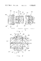
- FIG. 1 is a cut-away view of the main portions of a connector assembly of the present invention
- FIG. 2 is a cross-sectional view of a connector assembly of the present invention showing the shells and coupling ring in mated position;
- FIG. 3 is a view taken along the lines III--III of FIG. 2;
- FIG. 4 is an enlarged view of the upper portion of the assembly of FIG. 2, using a bayonet type rather than screw type securement, showing the relationship of the flange of the first shell, end wall of the second shell and the placement of the metallic strap;
- FIG. 5 is a plan view with cut-away portions of the metallic strap usable in the connector assembly.
- an electrical connector assembly 10 which includes a first shell 100, a second shell 200 and a coupling nut 300 that is mounted on the first shell 100 for connecting the first shell 100 and the second shell 200 in mating relationship.
- Typical components of the first shell 100 include one or more female type (socket) electrical contacts 170 retained within the shell 100 by inserts 110, 120 and 130.
- the outer surface of the first shell 100 includes one or more keys 101 for orienting the first shell 100 relative to the second shell 200.
- the contacts 170 are mounted within passages 131 through the inserts.
- the shell 100 includes a flange 140 which extends around the outer periphery thereof.
- Typical components of the second shell 200 include one or more axially extending recesses or keyways 201 for receiving the respective keys 101 on the first shell 100.
- the second shell includes one or more male type (pin) electrical contacts 270 that mate with the socket type contacts 170 of the first shell. These contacts 270 are retained in the second shell 200 by one or more inserts 230.
- the inserts 230 include a passage 231 along with means for retaining the contacts within the passage.
- the shell 200 includes a forward external thread 210 or other securing means.
- the coupling nut 300 is mounted over the rear section of the first shell 100, with internal threads 310, or other securing means, on the coupling nut adapted to mate with the external threads 210, or other securing means, on the second shell to bring the first and second shells together with the contacts mated.
- the coupling nut 300 is rotatably mounted on the first shell 100 by a snap ring 400, that is snapped into a groove 102 in the first shell 100, thus retaining the end wall 305 of the coupling nut 300 between the ring 400 and the flange 140. When so mated, the end wall 220 of the second shell 200 should abut the wall 160 of the flange 140 of the first shell 100.
- FIGS. 1 and 2 illustrate a conventional screw type securement
- FIG. 4 illustrates the invention in association with a conventional bayonet type securing means connector assembly construction.
- the present invention provides means for assuring metal to metal contact in this area.
- the means for assuring metal to metal contact comprise a first channel 180 formed in the wall 160 of flange 140 on the first shell 100, a cooperating second channel 190 formed about the front section of the first shell 100, and a resilient metallic member 500 situated within said channels in contact with both the first shell 100 and end wall 220 of the second shell 200.
- the flange 140 has a first channel 180 formed in the face 160 of the flange 140, which channel extends from corner 150 at its inner portion to a first retention wall 185 at its outer portion.
- a cooperating channel 190 is formed about the periphery of the front section of the first shell 100, adjacent the front section of the second shell 200 which terminates as end wall 220.
- the cooperating channel 190 extends from corner 150 at its front portion to a second retention wall 195 spaced therefrom.
- a resilient metallic member 500 is provided, which is preferably in the shape of an L-shaped metallic strap, the strap having a bowed leg portion 510 and a bowed stem portion 520.
- the metallic strap 500 is preferably constructed such that slots 530 are cut therein, with adjacent slots 530 cut from opposite sides of the strap 500 to form a sinuous pattern for the strap.
- the metallic strap 500 is situated in the assembly such that the leg portion 510 thereof is contained between the corner 150 and first retention wall 185 of the channel 180 formed in wall 160 of flange 140 of shell 100, while the stem portion 520 is contained between the corner 150 and second retention wall 195 of cooperating channel 190 about the periphery of the first shell 100.
- the resilient metal strap 500 is formed from a highly conductive metallic material or a conductively plated metallic material, with beryllium copper a preferred material.
- the resilient metallic strap 500 is preferably fabricated from flat spring stock and formed to fit about the outer periphery of the front section of the shell 100 within groove 190.
- the use of the slots 530 to form the strap 500 in a sinuous shape enables the strap to flex and open sufficiently to enable the strap to fit over the keys 101 on the first shell 100 and still return to a tight fit about the groove 190 in shell 100 after assembly.
- the strap 500 is passed over the keys 101 and the periphery of the first shell 100 and the stem portion 520 situated within the cooperating groove 190, with the leg portion 510 in the channel 180 of the flange 140.
- the coupling nut 300 is then fitted over the first shell 100 and rotatably secured thereto by means of the snap ring 400.
- the end wall will compress the bowed stem portion 520, forcing the leg portion 510 to flex towards the end wall 220 of second shell 200.
- the leg portion 510 is forced into the channel 180, tensioning the stem portion 520.
- leg portion 510 will be constantly flexed towards end wall 220 of the second shell 200 and will provide continuous metal to metal contact between the flange 140, through channel 180, even if built-up tolerances, vibrations, or the like, would cause a small gap to form between face 160 of the flange 140 and the end wall 220 of the second shell 200.
- a continuous shield is thus provided to prevent access of electromagnetic interference to the contacts contained within the electrical connector assembly.
Landscapes
- Details Of Connecting Devices For Male And Female Coupling (AREA)
Abstract
Description
Claims (8)
Priority Applications (3)
| Application Number | Priority Date | Filing Date | Title |
|---|---|---|---|
| US06/071,461 US4248492A (en) | 1979-08-31 | 1979-08-31 | Electrical connector assembly having means for shielding against electromagnetic interference |
| GB8024605A GB2059184B (en) | 1979-08-31 | 1980-07-28 | Electrical connector assembly with means for shielding against electromagnetic interference |
| FR8017081A FR2464575A1 (en) | 1979-08-31 | 1980-08-01 | ELECTRICAL CONNECTOR |
Applications Claiming Priority (1)
| Application Number | Priority Date | Filing Date | Title |
|---|---|---|---|
| US06/071,461 US4248492A (en) | 1979-08-31 | 1979-08-31 | Electrical connector assembly having means for shielding against electromagnetic interference |
Publications (1)
| Publication Number | Publication Date |
|---|---|
| US4248492A true US4248492A (en) | 1981-02-03 |
Family
ID=22101478
Family Applications (1)
| Application Number | Title | Priority Date | Filing Date |
|---|---|---|---|
| US06/071,461 Expired - Lifetime US4248492A (en) | 1979-08-31 | 1979-08-31 | Electrical connector assembly having means for shielding against electromagnetic interference |
Country Status (3)
| Country | Link |
|---|---|
| US (1) | US4248492A (en) |
| FR (1) | FR2464575A1 (en) |
| GB (1) | GB2059184B (en) |
Cited By (18)
| Publication number | Priority date | Publication date | Assignee | Title |
|---|---|---|---|---|
| EP0041420A1 (en) * | 1980-06-02 | 1981-12-09 | The Bendix Corporation | Electrical connector with provision for electromagnetic shielding |
| EP0041418A1 (en) * | 1980-06-02 | 1981-12-09 | The Bendix Corporation | Electrical connector with a securing connection for an associated electromagnetic shielding device |
| EP0080845A1 (en) * | 1981-11-23 | 1983-06-08 | M/A-COM Omni Spectra, Inc. | Coaxial connector assembly |
| US4423919A (en) | 1982-04-05 | 1984-01-03 | The Bendix Corporation | Electrical connector |
| US4470657A (en) * | 1982-04-08 | 1984-09-11 | International Telephone & Telegraph Corporation | Circumferential grounding and shielding spring for an electrical connector |
| US4502748A (en) * | 1983-11-21 | 1985-03-05 | Allied Corporation | Anti-decoupling device for an electrical connector |
| US4531805A (en) * | 1984-04-03 | 1985-07-30 | Allied Corporation | Electrical connector assembly having means for EMI shielding |
| US4583809A (en) * | 1984-04-02 | 1986-04-22 | Allied Corporation | Electrical connector assembly having means for EMI shielding |
| US4598959A (en) * | 1983-11-04 | 1986-07-08 | International Telephone And Telegraph Corporation | Electrical connector grounding ring |
| US4655533A (en) * | 1981-02-04 | 1987-04-07 | Itt Industries, Inc. | Electrical connector containing an annular shield and method of manufacture thereof |
| US4808126A (en) * | 1987-10-05 | 1989-02-28 | Itt Corporation | Electrical connector shield |
| US4808128A (en) * | 1984-04-02 | 1989-02-28 | Amphenol Corporation | Electrical connector assembly having means for EMI shielding |
| US4874337A (en) * | 1988-11-23 | 1989-10-17 | Amp Incorporated | Method of mounting a replaceable EMI spring strip |
| EP0355276A1 (en) * | 1988-08-12 | 1990-02-28 | Schaltbau Aktiengesellschaft | Connecting part such as a plug or socket to be fitted on a plugging panel |
| AU619133B2 (en) * | 1989-09-29 | 1992-01-16 | Hughes Aircraft Company | Self-aligning rf push-on connector |
| US5681177A (en) * | 1995-01-25 | 1997-10-28 | Amphenol Corporation | Anti-decoupling device |
| US20130149896A1 (en) * | 2011-12-12 | 2013-06-13 | Michael Holland | Signal continuity connector |
| US9397441B2 (en) | 2013-03-15 | 2016-07-19 | Cinch Connections, Inc. | Connector with anti-decoupling mechanism |
Families Citing this family (2)
| Publication number | Priority date | Publication date | Assignee | Title |
|---|---|---|---|---|
| AT387295B (en) * | 1982-06-08 | 1988-12-27 | Neutrik Ag | Electrical plug connection |
| US7753698B2 (en) | 2008-10-01 | 2010-07-13 | Amphenol Corporation | Grounding band for electrical connectors |
Citations (4)
| Publication number | Priority date | Publication date | Assignee | Title |
|---|---|---|---|---|
| US2762025A (en) * | 1953-02-11 | 1956-09-04 | Erich P Tilenius | Shielded cable connectors |
| US3521222A (en) * | 1967-11-24 | 1970-07-21 | Bunker Ramo | Cable connector |
| US3678445A (en) * | 1970-07-31 | 1972-07-18 | Itt | Electrical connector shield |
| US3835443A (en) * | 1973-04-25 | 1974-09-10 | Itt | Electrical connector shield |
-
1979
- 1979-08-31 US US06/071,461 patent/US4248492A/en not_active Expired - Lifetime
-
1980
- 1980-07-28 GB GB8024605A patent/GB2059184B/en not_active Expired
- 1980-08-01 FR FR8017081A patent/FR2464575A1/en not_active Withdrawn
Patent Citations (4)
| Publication number | Priority date | Publication date | Assignee | Title |
|---|---|---|---|---|
| US2762025A (en) * | 1953-02-11 | 1956-09-04 | Erich P Tilenius | Shielded cable connectors |
| US3521222A (en) * | 1967-11-24 | 1970-07-21 | Bunker Ramo | Cable connector |
| US3678445A (en) * | 1970-07-31 | 1972-07-18 | Itt | Electrical connector shield |
| US3835443A (en) * | 1973-04-25 | 1974-09-10 | Itt | Electrical connector shield |
Cited By (20)
| Publication number | Priority date | Publication date | Assignee | Title |
|---|---|---|---|---|
| EP0041418A1 (en) * | 1980-06-02 | 1981-12-09 | The Bendix Corporation | Electrical connector with a securing connection for an associated electromagnetic shielding device |
| EP0041420A1 (en) * | 1980-06-02 | 1981-12-09 | The Bendix Corporation | Electrical connector with provision for electromagnetic shielding |
| US4655533A (en) * | 1981-02-04 | 1987-04-07 | Itt Industries, Inc. | Electrical connector containing an annular shield and method of manufacture thereof |
| EP0080845A1 (en) * | 1981-11-23 | 1983-06-08 | M/A-COM Omni Spectra, Inc. | Coaxial connector assembly |
| US4426127A (en) | 1981-11-23 | 1984-01-17 | Omni Spectra, Inc. | Coaxial connector assembly |
| US4423919A (en) | 1982-04-05 | 1984-01-03 | The Bendix Corporation | Electrical connector |
| US4470657A (en) * | 1982-04-08 | 1984-09-11 | International Telephone & Telegraph Corporation | Circumferential grounding and shielding spring for an electrical connector |
| US4598959A (en) * | 1983-11-04 | 1986-07-08 | International Telephone And Telegraph Corporation | Electrical connector grounding ring |
| US4502748A (en) * | 1983-11-21 | 1985-03-05 | Allied Corporation | Anti-decoupling device for an electrical connector |
| US4583809A (en) * | 1984-04-02 | 1986-04-22 | Allied Corporation | Electrical connector assembly having means for EMI shielding |
| US4808128A (en) * | 1984-04-02 | 1989-02-28 | Amphenol Corporation | Electrical connector assembly having means for EMI shielding |
| US4531805A (en) * | 1984-04-03 | 1985-07-30 | Allied Corporation | Electrical connector assembly having means for EMI shielding |
| US4808126A (en) * | 1987-10-05 | 1989-02-28 | Itt Corporation | Electrical connector shield |
| EP0355276A1 (en) * | 1988-08-12 | 1990-02-28 | Schaltbau Aktiengesellschaft | Connecting part such as a plug or socket to be fitted on a plugging panel |
| US4874337A (en) * | 1988-11-23 | 1989-10-17 | Amp Incorporated | Method of mounting a replaceable EMI spring strip |
| AU619133B2 (en) * | 1989-09-29 | 1992-01-16 | Hughes Aircraft Company | Self-aligning rf push-on connector |
| US5681177A (en) * | 1995-01-25 | 1997-10-28 | Amphenol Corporation | Anti-decoupling device |
| US20130149896A1 (en) * | 2011-12-12 | 2013-06-13 | Michael Holland | Signal continuity connector |
| US8915753B2 (en) * | 2011-12-12 | 2014-12-23 | Holland Electronics, Llc | Signal continuity connector |
| US9397441B2 (en) | 2013-03-15 | 2016-07-19 | Cinch Connections, Inc. | Connector with anti-decoupling mechanism |
Also Published As
| Publication number | Publication date |
|---|---|
| FR2464575A1 (en) | 1981-03-06 |
| GB2059184A (en) | 1981-04-15 |
| GB2059184B (en) | 1983-10-12 |
Similar Documents
| Publication | Publication Date | Title |
|---|---|---|
| US4248492A (en) | Electrical connector assembly having means for shielding against electromagnetic interference | |
| US4673236A (en) | Connector assembly | |
| EP0040941B1 (en) | Electrical connector shield | |
| EP0473063B1 (en) | Overmolded shielded connector | |
| EP0626104B1 (en) | Power port terminal | |
| US4349241A (en) | Electrical connector assembly having enhanced EMI shielding | |
| US4687263A (en) | Shielding kit for electrical connectors terminating multiconductor 360 degree shielded cable | |
| US4423919A (en) | Electrical connector | |
| US5738544A (en) | Shielded electrical connector | |
| US5658170A (en) | Cable connector assembly | |
| US4938718A (en) | Cylindrical connector keying means | |
| US6299487B1 (en) | Connector with wear-resistant engagement means | |
| US4386819A (en) | RF Shielded assembly having capacitive coupling feature | |
| US3835443A (en) | Electrical connector shield | |
| US4894026A (en) | Miniature circular DIN connector | |
| CA1231150A (en) | Electrical connector assembly having means for emi shielding | |
| US4470657A (en) | Circumferential grounding and shielding spring for an electrical connector | |
| US4033654A (en) | Electrical connector | |
| US5096444A (en) | Flat F-port connector | |
| US20210296829A1 (en) | Plug connector, receptacle connector and connector assembly | |
| US4261628A (en) | Microphone connector | |
| JPS58189973A (en) | connector | |
| US4479691A (en) | Connector assembly | |
| US4483579A (en) | Electrical connector having improved coupling ring | |
| US5092794A (en) | Shielded electrical connector |
Legal Events
| Date | Code | Title | Description |
|---|---|---|---|
| AS | Assignment |
Owner name: ALLIED CORPORATION, A CORP. OF NY Free format text: MERGER;ASSIGNOR:BENDIX CORPORATION, THE,;REEL/FRAME:004765/0709 Effective date: 19850401 Owner name: CANADIAN IMPERIAL BANK OF COMMERCE, NEW YORK AGENC Free format text: SECURITY INTEREST;ASSIGNOR:AMPHENOL CORPORATION;REEL/FRAME:004879/0030 Effective date: 19870515 |
|
| AS | Assignment |
Owner name: AMPHENOL CORPORATION, LISLE, ILLINOIS A CORP. OF D Free format text: ASSIGNMENT OF ASSIGNORS INTEREST.;ASSIGNOR:ALLIED CORPORATION, A CORP. OF NY;REEL/FRAME:004844/0850 Effective date: 19870602 Owner name: AMPHENOL CORPORATION, A CORP. OF DE, ILLINOIS Free format text: ASSIGNMENT OF ASSIGNORS INTEREST;ASSIGNOR:ALLIED CORPORATION, A CORP. OF NY;REEL/FRAME:004844/0850 Effective date: 19870602 |
|
| AS | Assignment |
Owner name: BANKERS TRUST COMPANY, AS AGENT Free format text: SECURITY INTEREST;ASSIGNOR:AMPHENOL CORPORATION, A CORPORATION OF DE;REEL/FRAME:006035/0283 Effective date: 19911118 |
|
| AS | Assignment |
Owner name: AMPHENOL CORPORATION A CORP. OF DELAWARE Free format text: RELEASED BY SECURED PARTY;ASSIGNOR:CANADIAN IMPERIAL BANK OF COMMERCE;REEL/FRAME:006147/0887 Effective date: 19911114 |
|
| AS | Assignment |
Owner name: AMPHENOL CORPORATION, CONNECTICUT Free format text: RELEASE BY SECURED PARTY;ASSIGNOR:BANKERS TRUST COMPANY;REEL/FRAME:007317/0148 Effective date: 19950104 |