US4243255A - Low silhouette adjustable latch with secondary lock - Google Patents
Low silhouette adjustable latch with secondary lock Download PDFInfo
- Publication number
- US4243255A US4243255A US06/027,623 US2762379A US4243255A US 4243255 A US4243255 A US 4243255A US 2762379 A US2762379 A US 2762379A US 4243255 A US4243255 A US 4243255A
- Authority
- US
- United States
- Prior art keywords
- handle
- housing
- latch
- pivot
- lever
- Prior art date
- Legal status (The legal status is an assumption and is not a legal conclusion. Google has not performed a legal analysis and makes no representation as to the accuracy of the status listed.)
- Expired - Lifetime
Links
Images
Classifications
-
- E—FIXED CONSTRUCTIONS
- E05—LOCKS; KEYS; WINDOW OR DOOR FITTINGS; SAFES
- E05C—BOLTS OR FASTENING DEVICES FOR WINGS, SPECIALLY FOR DOORS OR WINDOWS
- E05C19/00—Other devices specially designed for securing wings, e.g. with suction cups
- E05C19/10—Hook fastenings; Fastenings in which a link engages a fixed hook-like member
- E05C19/12—Hook fastenings; Fastenings in which a link engages a fixed hook-like member pivotally mounted around an axis
- E05C19/14—Hook fastenings; Fastenings in which a link engages a fixed hook-like member pivotally mounted around an axis with toggle action
-
- Y—GENERAL TAGGING OF NEW TECHNOLOGICAL DEVELOPMENTS; GENERAL TAGGING OF CROSS-SECTIONAL TECHNOLOGIES SPANNING OVER SEVERAL SECTIONS OF THE IPC; TECHNICAL SUBJECTS COVERED BY FORMER USPC CROSS-REFERENCE ART COLLECTIONS [XRACs] AND DIGESTS
- Y10—TECHNICAL SUBJECTS COVERED BY FORMER USPC
- Y10S—TECHNICAL SUBJECTS COVERED BY FORMER USPC CROSS-REFERENCE ART COLLECTIONS [XRACs] AND DIGESTS
- Y10S292/00—Closure fasteners
- Y10S292/49—Toggle catches
-
- Y—GENERAL TAGGING OF NEW TECHNOLOGICAL DEVELOPMENTS; GENERAL TAGGING OF CROSS-SECTIONAL TECHNOLOGIES SPANNING OVER SEVERAL SECTIONS OF THE IPC; TECHNICAL SUBJECTS COVERED BY FORMER USPC CROSS-REFERENCE ART COLLECTIONS [XRACs] AND DIGESTS
- Y10—TECHNICAL SUBJECTS COVERED BY FORMER USPC
- Y10T—TECHNICAL SUBJECTS COVERED BY FORMER US CLASSIFICATION
- Y10T292/00—Closure fasteners
- Y10T292/08—Bolts
- Y10T292/0911—Hooked end
- Y10T292/0913—Sliding and swinging
- Y10T292/0914—Operating means
- Y10T292/0917—Lever
-
- Y—GENERAL TAGGING OF NEW TECHNOLOGICAL DEVELOPMENTS; GENERAL TAGGING OF CROSS-SECTIONAL TECHNOLOGIES SPANNING OVER SEVERAL SECTIONS OF THE IPC; TECHNICAL SUBJECTS COVERED BY FORMER USPC CROSS-REFERENCE ART COLLECTIONS [XRACs] AND DIGESTS
- Y10—TECHNICAL SUBJECTS COVERED BY FORMER USPC
- Y10T—TECHNICAL SUBJECTS COVERED BY FORMER US CLASSIFICATION
- Y10T292/00—Closure fasteners
- Y10T292/08—Bolts
- Y10T292/1043—Swinging
- Y10T292/1075—Operating means
- Y10T292/1083—Rigid
- Y10T292/1092—Swinging catch
Definitions
- the present invention relates to the field of latches of the type particularly adaptable for joining and securing two adjacent and generally planar members. More particularly the invention pertains to an over center or toggle type latch including a separate drawhook and activating handle operatively attached to a base and additionally having means to adjust the latch tension and means to secure the latch in a fully closed position against accidental opening.
- Latches of this general construction and including the various features described above are well-known in the art.
- U.S. Pat. No. 3,936,082 discloses an overcenter tension latch with an anti-release or secondary locking mechanism. Also disclosed therein are means for varying the tension in the latch.
- the secondary lock is activated by the same general motion employed in raising the handle since it operates generally in the same direction as the movement of the handle.
- the adjustment means is not readily accessible when the latch is in the closed position and, as a result, tension adjustments must be made in an open position with trial and error methods employed to reach the proper tension.
- U.S. Pat. No. 3,237,978 discloses a similar type of latch, including a secondary locking mechanism and a tension adjustment means.
- the secondary locking means operates in the same direction as handle movement when the latter is lifted to open the latch.
- Such unidirectional movement of the secondary locking mechanism and the handle itself inhibits the efficacy of the device to remain locked against an accidentally applied unidirectional force.
- the secondary locking mechanisms disclosed in the foregoing patents also occupy substantially greater height above the members to be connected than would ordinarily be required for the remainder of the latch mechanism. As a result, such secondary locking mechanisms detract from the low horizontal profile or "silhouette" of the overall latch.
- U.S. Pat. Nos. 3,519,298 and 3,602,723 also disclose latches with secondary locking or anti-release mechanisms. These mechanisms also operate generally in planes perpendicular to the latch bases and protrude substantially above the general horizontal profile of the latches.
- the latch tension adjustment screw is fully accessible when the latch is closed from the rear of the latch through a channel-like opening defined by the latch handle.
- a secondary locking mechanism is mounted in the same area of the handle, but is offset laterally from the longitudinal center line of the latch and adjustment screw and does not, therefore, interfere with access to the adjustment mechanism.
- the secondary locking mechanism occupies no greater vertical depth than the adjustment mechanism, and does not detract from the low silhouette of the latch.
- the secondary locking mechanism is engaged in the same thumb-and-finger motion used to grasp the handle for opening, however, the force required to disengage a secondary lock is directed generally perpendicularly to the force required to lift the handle for opening the latch.
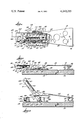
- FIG. 1 is a top plan view of the latch with certain portions cut away to disclose details of the operating mechanisms.
- FIG. 2 is a side elevation of the latch shown in FIG. 1 and also having certain portions cut away.
- FIG. 3 is a side elevation similar to FIG. 2, but showing the latch handle in the raised open position.
- a latch mechanism includes a latch assembly 10 attached to the surface of a member 12 and a strike plate 14 attached to an adjacent member 16 to be joined to member 12.
- the latch assembly includes a drawhook 18 adapted to engage a catch 20 on the strike plate 14 to draw members 12 and 16 together.
- the latch assembly 10 includes a base 22 including flat, laterally extending mounting flanges 23 adapted to lie flush against and be attached to the surface of member 12, as with screws 24. Formed integrally with and extending perpendicularly from the mounting flanges 23 are a pair of side walls 26 joined at their upper edges by an integral top plate 28. The side walls 26 and top plate 28 form an elongated rectangular housing 29 for the tension adjusting mechanism to be described hereinafter.
- a handle 30 includes a flat top surface 32 and two downwardly depending side flanges 34, the latter providing the usual thumb-and-finger engaging surfaces for operating the latch.
- the side flanges 34 extend forwardly of the top surface 32 to form a pair of spaced legs 36.
- the ends of the legs 36 are provided with holes in which are journaled the reduced ends 38 of a handle pivot pin 40.
- Pivot pin 40 extends through elongated aligned apertures 42 in the side walls 26 of the housing 29 to provide pivotal attachment of the handle 30 to the base 22.
- the legs 36 In the closed position of the latch shown in FIGS. 1 and 2 of the drawing, the legs 36 straddle the housing 29 and lie alongside and generally parallel to the side walls 26.
- the drawhook 18 has a generally planar body 44 terminating in a curved hook 46 adapted to engage the catch 20 on strike plate 14. Extending rearwardly from the drawhook body 44 are a pair of spaced arms 48 adapted to straddle, in the closed position, the legs 36 of the handle and the housing 29 of the base. The ends of the drawhook arms 48 are pivotally attached to the legs 36 of the handle 30 with a pair of rivets 50 at a position on the legs 36 intermediate the handle pivot 40 and the side flanges 34. Further, the common axis of the rivets 50 lies slightly below, or closer to the mounting surface of member 12 than, the axis of the handle pivot pin 40 in the latched position.
- an adjustment screw 52 is disposed within the base housing 29.
- the end wall 54 of the housing 29 which may conveniently comprise a downturned extension of the housing top plate 28, is provided with a hole 56 in which is journaled the shank 53 of the adjustment screw.
- the head 58 of the adjustment screw bears against the outer surface of the end wall 54 of the housing and the shank 53 extends into the housing 29 into threaded engagement with a tapped cross hole 41 in the pivot pin 40.
- the tension in the drawhook 18 is transmitted to the adjustment screw 52 by way of the drawhook arms 48, handle legs 36 and pivot pin 40, and the full tension load is carried by the bearing engagement of the adjustment screw head 58 on the end wall 54 of the housing 29.
- the pivot pin 40 extends through apertures 42 in the side walls 26 of the housing. Apertures 42 are elongated in the direction of the axis of the adjustment screw 52 and, as the screw is turned in the hole 56 in the housing end wall 54, its threaded connection with the cross hole 41 of the pivot pin 40 allows the pivot pin (and the pivotally connected handle 30 and drawhook 18) to be adjusted within the limits of the length of the elongated apertures 42.
- a coiled bias spring 60 is disposed around the shank 53 of the adjustment screw 52 and exerts a compressive force upon the pivot pin 40 at one end and the inside surface of the housing end wall 54 at the other end to position the adjustment screw and hold the head 58 thereof in contact with end wall 54.
- the force of the bias spring 60 on the pivot pin also serves to maintain the drawhook 18 in its adjusted position when unlatched. Otherwise, the unlatched drawhook could move freely by an amount equal to the distance from the pivot pin 40 in its adjusted position to the rear edges of the apertures 42 and, as a result, prevent proper initial engagement of the hook 46 and catch 20 as the drawhook is pivoted downwardly toward the strike plate 14 for relatching.
- the latch assembly 10 presents a very shallow vertical profile or low "silhouette", which is extremely desireable in many applications where the vertical projection of the latch above the members 12 and 16 must be kept as small as possible
- the adjustment screw 52 is disposed completely within this low silhouette, yet its head 58 is fully accessible through the channel-like opening formed by the handle top surface 32 and side flanges 34, even when the latch is closed.
- the head 58 is conveniently provided with a hex recess 59 which is readily engageable by a screw driver, allen wrench, or similar tool 62 to vary the tension of the assembly in the latched position.
- a secondary locking mechanism 64 is provided.
- the secondary locking mechanism is attached to the handle 30 and cooperates with a notch 66 in one side wall 26 of the housing 29 to realeasably hold the assembly in its latched position.
- the secondary lock 64 includes an activating lever 67 having a generally L-shaped cross section with a flat upper surface 68 and an outer surface 70 disposed substantially perpendicular thereto.
- the upper surface 68 is disposed substantially within a narrow elongated slot 72 in a side flange 34 of the handle slightly below the top surface 32.
- the upper surface 68 is pivotally mounted to a vertically disposed locking pivot 74 attached to and depending downwardly from the handle top surface 32 on the inside thereof.
- the outer surface 70 of the lever 67 has the shape, when viewed in plan in FIG. 1, of a shallow V defining an obtuse angle.
- the outer surface 70 extends downwardly beyond the lower edge of elongated slot 72 and, as the lever 67 is pivoted about locking pivot 74, the legs of the V will alternately bear against the side flange 34 of the handle between the locked solid line and unlocked dotted line positions of FIG. 1.
- the angle of rotation between these positions is approximately equal to the supplement of the obtuse angle of the V.
- a portion of the upper surface 68 of the lever 67 is cut away as at 76 to provide a locking detent 78 adapted to enter the notch 66 in the side wall 26 of housing 29 and prevent upward pivotal movement of the handle about the pivot pin 40 from its latched position.
- a torsion spring 79 is coiled about the locking lever pivot 74 and captured between the underside of the upper surface 68 and an enlarged head 82 at the end of pivot 74.
- the free ends 80 and 81 of the spring 79 bear against the inside surface of handle side flange 34 and the end of the lever 67 opposite the locking detent 78, respectively.
- the end 81 of spring 79 may be bent and hooked in a small hole 84 in the upper surface 68 of the lever 67.
- the detent is biased into locking engagement in the notch 66 while the opposite end of the lever is biased outwardly of the latch handle 30.
- the outwardly biased portion of outer surface 70 (one leg of the shallow V-form surface) provides a convenient thumb-or-finger engagable surface 71 for disengaging the secondary lock 64 by pressing the same inwardly against the bias of torsion spring 79.
- the locking detent 78 is provided with an upwardly curved end 83 such that its rounded lower surface will ride over the corner formed by the junction of the housing top plate 28 and side wall 26 as the latch handle 30 is pivoted downwardly toward the latched position. The resultant against the bias of torsion spring 79 and snap back into the notch 66 as the handle reaches the overcenter latched position.
- the mechanism of the secondary lock 64 occupies largely the same horizontal position above the member 12 on which the latch assembly 10 is mounted as the adjustment screw 52.
- the secondary lock 64 offset laterally from the longitudinal centerline of the latch, it does not interfere with the operation of the adjustment screw 52 or in any way inhibit access to it for adjustment of tension in the latched position.
- no part of the secondary lock 64 ever extends above the coplanar housing top plate 28, handle top surface 32, and drawhook body 44 in the latched position and, therefore, does not detract from the low silhouette of the latch.
- the secondary lock 64 is conveniently opened in the same thumb-and-finger action used to grasp the side flanges 34 of the handle to open the latch.
- the force required to depress the surface 71 to unlock the latch must act generally perpendicularly to the force required to lift the handle 30, thereby minimizing the chance of accidental opening of the latch.
- the top plate 23 of the housing 29 and the top surface 32 of the handle 30 provide a substantially continuous protective cover for both the tension adjustment and secondary lock mechanisms, further reducing the possibility of inadvertant movement or damage.
Landscapes
- Engineering & Computer Science (AREA)
- Mechanical Engineering (AREA)
- Clamps And Clips (AREA)
Abstract
Description
Claims (6)
Priority Applications (3)
| Application Number | Priority Date | Filing Date | Title |
|---|---|---|---|
| US06/027,623 US4243255A (en) | 1979-04-06 | 1979-04-06 | Low silhouette adjustable latch with secondary lock |
| EP80630010A EP0018304B1 (en) | 1979-04-06 | 1980-04-03 | Low silhouette adjustable latch with secondary lock |
| DE8080630010T DE3062869D1 (en) | 1979-04-06 | 1980-04-03 | Low silhouette adjustable latch with secondary lock |
Applications Claiming Priority (1)
| Application Number | Priority Date | Filing Date | Title |
|---|---|---|---|
| US06/027,623 US4243255A (en) | 1979-04-06 | 1979-04-06 | Low silhouette adjustable latch with secondary lock |
Publications (1)
| Publication Number | Publication Date |
|---|---|
| US4243255A true US4243255A (en) | 1981-01-06 |
Family
ID=21838793
Family Applications (1)
| Application Number | Title | Priority Date | Filing Date |
|---|---|---|---|
| US06/027,623 Expired - Lifetime US4243255A (en) | 1979-04-06 | 1979-04-06 | Low silhouette adjustable latch with secondary lock |
Country Status (3)
| Country | Link |
|---|---|
| US (1) | US4243255A (en) |
| EP (1) | EP0018304B1 (en) |
| DE (1) | DE3062869D1 (en) |
Cited By (20)
| Publication number | Priority date | Publication date | Assignee | Title |
|---|---|---|---|---|
| US4588216A (en) * | 1984-08-14 | 1986-05-13 | The United States Of America As Represented By The Secretary Of The Air Force | Over-center toggle latch |
| US4602812A (en) * | 1983-05-20 | 1986-07-29 | Hartwell Corporation | Adjustable double hook latch |
| US4688835A (en) * | 1984-11-21 | 1987-08-25 | Rockwell International Corporation | Adjustable latching apparatus and method of latchably pressing and holding together |
| US4702504A (en) * | 1986-07-24 | 1987-10-27 | The United States Of America As Represented By The Secretary Of The Air Force | Container latch |
| US4782673A (en) * | 1983-12-23 | 1988-11-08 | Samsonite Corporation | Connection device |
| US5445422A (en) * | 1993-05-21 | 1995-08-29 | The Eastern Company | Handle operated draw latch with safety catch |
| USD378985S (en) * | 1995-09-08 | 1997-04-29 | The Eastern Company | Handle operated draw latch assembly with lockable safety catch |
| US5655799A (en) * | 1994-10-24 | 1997-08-12 | Takigen Manufacturing Co. Ltd. | Latch assembly |
| US5667258A (en) * | 1994-10-24 | 1997-09-16 | Takigen Manufacturing Co. Ltd. | Latch assembly |
| US5667261A (en) * | 1993-05-21 | 1997-09-16 | The Eastern Company | Handle operated heavy duty draw latch with safety catch |
| US20030159867A1 (en) * | 2002-02-22 | 2003-08-28 | Connett Jerry J. | Hood latching system |
| US6712405B2 (en) * | 2000-11-07 | 2004-03-30 | Bombardier Recreational Products Inc. | Latch mechanism for a snowmobile engine cover |
| US6840551B2 (en) | 2000-06-17 | 2005-01-11 | Howard S Cooke & Co Limited | Over-center latch |
| US20060076785A1 (en) * | 2002-10-30 | 2006-04-13 | Lars Eriksson | Locking means for an over-centre fastener |
| GB2421364A (en) * | 2004-12-17 | 2006-06-21 | Liang Tei Co Ltd | Adjustable fastening |
| US20110068588A1 (en) * | 2009-09-09 | 2011-03-24 | Eduard Kopylov | Draw latch with safety catch |
| WO2012173840A1 (en) * | 2011-06-17 | 2012-12-20 | Snap-On Incorporated | Latch mechanism for front opening lid |
| US8764072B2 (en) * | 2010-10-21 | 2014-07-01 | Aircelle | Locking device with mechanical detection of closing and opening |
| EP2669881A4 (en) * | 2011-01-26 | 2015-10-28 | Unilumin Group Co Ltd | Latching connection device and led cabinet, led display screen provided with the same |
| US10759562B2 (en) | 2016-01-14 | 2020-09-01 | Brian Matthew Sneddon | Storage device |
Families Citing this family (3)
| Publication number | Priority date | Publication date | Assignee | Title |
|---|---|---|---|---|
| EP0142965B1 (en) * | 1983-11-11 | 1989-01-18 | Colt International Holdings A.G. | Superimposed member for roof openings of buildings |
| US4540206A (en) * | 1984-04-30 | 1985-09-10 | Southco, Inc. | Adjustable draw latch |
| CN201573587U (en) | 2009-10-27 | 2010-09-08 | 宁波生达电器有限公司 | Locking mechanism for truck cover of pick-up truck |
Citations (4)
| Publication number | Priority date | Publication date | Assignee | Title |
|---|---|---|---|---|
| US1400953A (en) * | 1920-11-10 | 1921-12-20 | Carl R Hennicke | Hood-fastener |
| US1898742A (en) * | 1931-06-27 | 1933-02-21 | Benjamin Electric Mfg Co | Toggle latch |
| US3936082A (en) * | 1974-10-11 | 1976-02-03 | The Nielsen Hardware Corporation | Catch with anti-release latch |
| US3998481A (en) * | 1975-05-01 | 1976-12-21 | Minnesota Mining And Manufacturing Company | Draw and pull latch |
Family Cites Families (5)
| Publication number | Priority date | Publication date | Assignee | Title |
|---|---|---|---|---|
| US3237978A (en) * | 1964-10-26 | 1966-03-01 | Gunnar E Swanson | Fastening device |
| US3519298A (en) * | 1967-02-24 | 1970-07-07 | Rex Chainbelt Inc | Positive lock for toggle latch |
| US3602723A (en) * | 1969-07-07 | 1971-08-31 | Gunnar E Swanson | Catch with antirelease latch |
| US4053177A (en) * | 1976-06-08 | 1977-10-11 | Tridair Industries | Adjustable latch |
| US4116479A (en) * | 1977-01-17 | 1978-09-26 | Hartwell Corporation | Adjustable flush mounted hook latch |
-
1979
- 1979-04-06 US US06/027,623 patent/US4243255A/en not_active Expired - Lifetime
-
1980
- 1980-04-03 DE DE8080630010T patent/DE3062869D1/en not_active Expired
- 1980-04-03 EP EP80630010A patent/EP0018304B1/en not_active Expired
Patent Citations (4)
| Publication number | Priority date | Publication date | Assignee | Title |
|---|---|---|---|---|
| US1400953A (en) * | 1920-11-10 | 1921-12-20 | Carl R Hennicke | Hood-fastener |
| US1898742A (en) * | 1931-06-27 | 1933-02-21 | Benjamin Electric Mfg Co | Toggle latch |
| US3936082A (en) * | 1974-10-11 | 1976-02-03 | The Nielsen Hardware Corporation | Catch with anti-release latch |
| US3998481A (en) * | 1975-05-01 | 1976-12-21 | Minnesota Mining And Manufacturing Company | Draw and pull latch |
Cited By (29)
| Publication number | Priority date | Publication date | Assignee | Title |
|---|---|---|---|---|
| US4602812A (en) * | 1983-05-20 | 1986-07-29 | Hartwell Corporation | Adjustable double hook latch |
| US4782673A (en) * | 1983-12-23 | 1988-11-08 | Samsonite Corporation | Connection device |
| US4588216A (en) * | 1984-08-14 | 1986-05-13 | The United States Of America As Represented By The Secretary Of The Air Force | Over-center toggle latch |
| US4688835A (en) * | 1984-11-21 | 1987-08-25 | Rockwell International Corporation | Adjustable latching apparatus and method of latchably pressing and holding together |
| US4702504A (en) * | 1986-07-24 | 1987-10-27 | The United States Of America As Represented By The Secretary Of The Air Force | Container latch |
| US5667261A (en) * | 1993-05-21 | 1997-09-16 | The Eastern Company | Handle operated heavy duty draw latch with safety catch |
| US5445422A (en) * | 1993-05-21 | 1995-08-29 | The Eastern Company | Handle operated draw latch with safety catch |
| US5655799A (en) * | 1994-10-24 | 1997-08-12 | Takigen Manufacturing Co. Ltd. | Latch assembly |
| US5667258A (en) * | 1994-10-24 | 1997-09-16 | Takigen Manufacturing Co. Ltd. | Latch assembly |
| USD378985S (en) * | 1995-09-08 | 1997-04-29 | The Eastern Company | Handle operated draw latch assembly with lockable safety catch |
| US6840551B2 (en) | 2000-06-17 | 2005-01-11 | Howard S Cooke & Co Limited | Over-center latch |
| US6712405B2 (en) * | 2000-11-07 | 2004-03-30 | Bombardier Recreational Products Inc. | Latch mechanism for a snowmobile engine cover |
| US20030159867A1 (en) * | 2002-02-22 | 2003-08-28 | Connett Jerry J. | Hood latching system |
| US6719077B2 (en) * | 2002-02-22 | 2004-04-13 | International Truck Intellectual Property Company, Llc | Hood latching system |
| US20060076785A1 (en) * | 2002-10-30 | 2006-04-13 | Lars Eriksson | Locking means for an over-centre fastener |
| GB2421364A (en) * | 2004-12-17 | 2006-06-21 | Liang Tei Co Ltd | Adjustable fastening |
| GB2421364B (en) * | 2004-12-17 | 2006-11-22 | Liang Tei Co Ltd | Electrical connector |
| US20110068588A1 (en) * | 2009-09-09 | 2011-03-24 | Eduard Kopylov | Draw latch with safety catch |
| US8186728B2 (en) * | 2009-09-09 | 2012-05-29 | Eduard Kopylov | Draw latch with safety catch |
| US8764072B2 (en) * | 2010-10-21 | 2014-07-01 | Aircelle | Locking device with mechanical detection of closing and opening |
| EP2669881A4 (en) * | 2011-01-26 | 2015-10-28 | Unilumin Group Co Ltd | Latching connection device and led cabinet, led display screen provided with the same |
| GB2506780A (en) * | 2011-06-17 | 2014-04-09 | Snap On Tools Corp | Latch mechanism for front opening lid |
| CN103620135A (en) * | 2011-06-17 | 2014-03-05 | 施耐宝公司 | Latch mechanism for front opening lid |
| WO2012173840A1 (en) * | 2011-06-17 | 2012-12-20 | Snap-On Incorporated | Latch mechanism for front opening lid |
| US9199370B2 (en) | 2011-06-17 | 2015-12-01 | Snap-On Incorporated | Latch mechanism for front opening lid |
| CN103620135B (en) * | 2011-06-17 | 2016-08-17 | 施耐宝公司 | Latch mechanism for front open type lid |
| GB2506780B (en) * | 2011-06-17 | 2018-06-27 | Snap On Tools Corp | Latch mechanism for front opening lid |
| US10759562B2 (en) | 2016-01-14 | 2020-09-01 | Brian Matthew Sneddon | Storage device |
| US11565847B2 (en) | 2016-01-14 | 2023-01-31 | Brian Matthew Sneddon | Storage device |
Also Published As
| Publication number | Publication date |
|---|---|
| EP0018304B1 (en) | 1983-04-27 |
| DE3062869D1 (en) | 1983-06-01 |
| EP0018304A1 (en) | 1980-10-29 |
Similar Documents
| Publication | Publication Date | Title |
|---|---|---|
| US4243255A (en) | Low silhouette adjustable latch with secondary lock | |
| US5664813A (en) | Lever latch | |
| US4693503A (en) | Lever latch | |
| US4261602A (en) | Security lock | |
| US4683736A (en) | Cabinet lock with recessed handle | |
| EP1009898B1 (en) | Vehicle hood latch with retracting secondary release arm | |
| US5127686A (en) | Door closure assembly | |
| US4159137A (en) | Adjustable multipivot panel latch | |
| US4307906A (en) | Adjustable toggle latch and safety catch | |
| US6042156A (en) | Overcenter double jaw latch mechanism | |
| US4413849A (en) | Tool-operated flush-mountable latch | |
| CA1235452A (en) | Cabinet lock with recessed handle | |
| US4132438A (en) | Deadlock latch | |
| US6840551B2 (en) | Over-center latch | |
| US5033778A (en) | Integral over-center toggle latch for use with a molded case | |
| US4060267A (en) | Adjustable door latch | |
| US5015020A (en) | Vehicular door locking device | |
| US4676534A (en) | Lock assembly | |
| US20020116785A1 (en) | Pivoting-handle device | |
| US2876031A (en) | Box lid fastener | |
| JPH1018685A (en) | Sash pulley type runner unit | |
| JP7194449B2 (en) | door stop device | |
| JP4521796B2 (en) | Locking device for sliding door lock | |
| JP2700219B2 (en) | Latch device for sliding door | |
| WO2003004813A1 (en) | Latch |
Legal Events
| Date | Code | Title | Description |
|---|---|---|---|
| AS | Assignment |
Owner name: WILMINGTON TRUST COMPANY, RODNEY SQUARE NORTH, WIL Free format text: SECURITY INTEREST;ASSIGNOR:REXNORD INC.;REEL/FRAME:004817/0047 Effective date: 19870430 Owner name: WADE, WILLIAM J., RODNEY SQUARE NORTH, WILMINGTON Free format text: SECURITY INTEREST;ASSIGNOR:REXNORD INC.;REEL/FRAME:004817/0047 Effective date: 19870430 |
|
| AS | Assignment |
Owner name: REXNORD HOLDINGS INC., 350 N. SUNNY SLOPE, BROOKFI Free format text: ASSIGNMENT OF ASSIGNORS INTEREST.;ASSIGNOR:REXNORD INC., A CORP. OF WI;REEL/FRAME:004938/0476 Effective date: 19880808 |
|
| AS | Assignment |
Owner name: WILMINGTON TRUST COMPANY AND WADE WILLIAM J. AS TR Free format text: ASSIGNMENT OF ASSIGNORS INTEREST. AMENDED SECURITY AGREEMENT;ASSIGNOR:REXNORD HOLDINGS INC., A CORP. OF DE;REEL/FRAME:004945/0853 Effective date: 19880816 Owner name: WILMINGTON TRUST COMPANY AND WADE WILLIAM J. AS TR Free format text: ASSIGNMENT OF ASSIGNORS INTEREST;ASSIGNOR:REXNORD HOLDINGS INC., A CORP. OF DE;REEL/FRAME:004945/0853 Effective date: 19880816 |
|
| AS | Assignment |
Owner name: FAIRCHILD INDUSTRIES, INC., WISCONSIN Free format text: ASSIGNMENT OF ASSIGNORS INTEREST.;ASSIGNOR:REXNORD HOLDINGS INC., A CORP. OF DE;REEL/FRAME:005152/0326 Effective date: 19890818 |
|
| AS | Assignment |
Owner name: VSI CORPORATION, A CORP. OF DE, WISCONSIN Free format text: ASSIGNMENT OF ASSIGNORS INTEREST.;ASSIGNOR:FAIRCHILD INDUSTRIES, INC.;REEL/FRAME:005363/0304 Effective date: 19890818 |
|
| AS | Assignment |
Owner name: WILMINGTON TRUST COMPANY, A DE BANKING CORP. Free format text: SECURITY INTEREST;ASSIGNOR:VSI CORPORATION, A DE CORP.;REEL/FRAME:005496/0572 Effective date: 19890818 |
|
| AS | Assignment |
Owner name: CITICORP NORTH AMERICA, INC., ILLINOIS Free format text: ASSIGNMENT OF ASSIGNORS INTEREST;ASSIGNORS:WILMINGTON TRUST COMPANY;WADE, WILLIAM J.;REEL/FRAME:007674/0919 Effective date: 19950222 Owner name: CITICORP NORTH AMERICA, INC., ILLINOIS Free format text: ASSIGNMENT OF ASSIGNORS INTEREST;ASSIGNORS:WILMINGTON TRUST COMPANY;WADE, WILLIAM J.;REEL/FRAME:007677/0077 Effective date: 19950222 |
|
| AS | Assignment |
Owner name: FAIRCHILD HOLDING CORP., VIRGINIA Free format text: ASSIGNMENT OF ASSIGNORS INTEREST;ASSIGNOR:CORPORATION VSI;REEL/FRAME:008013/0643 Effective date: 19960523 |
|
| AS | Assignment |
Owner name: CITICORP USA, INC., NEW YORK Free format text: SECURITY AGREEMENT;ASSIGNOR:FAIRCHILD HOLDING CORP.;REEL/FRAME:008290/0639 Effective date: 19960729 |
|
| AS | Assignment |
Owner name: CITICORP USA, INC., NEW YORK Free format text: REAFFIRMATION AND AMENDMENT OF PATENT SECURITY AGREEMENT;ASSIGNOR:FAIRCHILD HOLDING CORP.;REEL/FRAME:008660/0163 Effective date: 19970718 |
|
| AS | Assignment |
Owner name: CITICORP USA, INC., NEW YORK Free format text: AMENDED AND RESTATED PATENT SECURITY AGREEMENT;ASSIGNOR:FAIRCHILD HOLDING CORP.;REEL/FRAME:008967/0114 Effective date: 19971219 |
|
| AS | Assignment |
Owner name: CITICORP USA, INC., NEW YORK Free format text: SECURITY AGREEMENT;ASSIGNOR:FAIRCHILD HOLDING CORP.;REEL/FRAME:009958/0047 Effective date: 19990420 |
|
| AS | Assignment |
Owner name: FAIRCHILD HOLDING CORP., VIRGINIA Free format text: RELEASE BY SECURED PARTY;ASSIGNOR:CITICORP USA, INC.;REEL/FRAME:010180/0395 Effective date: 19990513 |
|
| AS | Assignment |
Owner name: CITICORP USA, INC., NEW YORK Free format text: SECURITY INTEREST;ASSIGNOR:FAIRCHILD HOLDING CORP.;REEL/FRAME:010197/0395 Effective date: 19990420 |