US4230933A - Electric air heating element - Google Patents
Electric air heating element Download PDFInfo
- Publication number
- US4230933A US4230933A US05/878,945 US87894578A US4230933A US 4230933 A US4230933 A US 4230933A US 87894578 A US87894578 A US 87894578A US 4230933 A US4230933 A US 4230933A
- Authority
- US
- United States
- Prior art keywords
- heating element
- coil
- notches
- fins
- slots
- Prior art date
- Legal status (The legal status is an assumption and is not a legal conclusion. Google has not performed a legal analysis and makes no representation as to the accuracy of the status listed.)
- Expired - Lifetime
Links
Images

Classifications
-
- H—ELECTRICITY
- H05—ELECTRIC TECHNIQUES NOT OTHERWISE PROVIDED FOR
- H05B—ELECTRIC HEATING; ELECTRIC LIGHT SOURCES NOT OTHERWISE PROVIDED FOR; CIRCUIT ARRANGEMENTS FOR ELECTRIC LIGHT SOURCES, IN GENERAL
- H05B3/00—Ohmic-resistance heating
- H05B3/10—Heater elements characterised by the composition or nature of the materials or by the arrangement of the conductor
- H05B3/16—Heater elements characterised by the composition or nature of the materials or by the arrangement of the conductor the conductor being mounted on an insulating base
-
- A—HUMAN NECESSITIES
- A45—HAND OR TRAVELLING ARTICLES
- A45D—HAIRDRESSING OR SHAVING EQUIPMENT; EQUIPMENT FOR COSMETICS OR COSMETIC TREATMENTS, e.g. FOR MANICURING OR PEDICURING
- A45D20/00—Hair drying devices; Accessories therefor
- A45D20/22—Helmets with hot air supply or ventilating means, e.g. electrically heated air current
- A45D20/38—Arrangement of the electric heating means
Definitions
- Heating elements for hair dryers should be as short as possible in order to reduce the weight of the appliance and to make it easy to handle; on the other hand it should present an adequate heat transfer surface while offering a minimum of flow resistance, with a view to permit the provision of a small fan and fan motor in the dryer.
- the most suitable heating element answering the above requirements is in the shape of a ribbon-shaped resistor helically wound on a spider-shaped core, in such a manner that the ribbon surfaces of all windings are parallel to the air flow. This design ensures a minimum of flow resistance, since the front surface offered to the air flow by the thin resistor is very small compared with the total heat exchange area. A high heat exchange coefficient is attained by the air spaces between adjoining coil windings, because they interrupt the boundary layer apt to form along a plain continuous surfaces, and thus create air turbulence.
- the heating element which adapted to be positioned in a cylindrical of conical duct of a hair dryer or other apparatus delivering hot air, comprises a solid star-shaped coil-carrier of a non-conductive and heat-resistant material, in the shape of at least four longitudinal fins extending in radial direction from a common jointing line.
- the outer edges of all fins are serrated by substantially equidistant rectangular slots of different depth as measured from said outer edge of each fin, and a ribbon-shaped resistor is wound helically around said coil carrier to form a coil.
- the windings are laid in successive rectangular slots with the ribbon surface substantially parallel to the outer fin edge and to the air flow.
- the resulting coil thus comprises at least two parallel surfaces of resistor windings which, in the case of four fins, form at least two coaxial square cylinders or cylinder frustums.
- each fin edge is serrated by alternate slots of shallow depth and of greater depth respectively, thus forming two parallel layers of resistor windings.
- each fin In order to provide a larger distance between the coil and the duct walls both end portions of each fin are radially extended to a greater length than its serrated edge, which end portions serve to firmly secure the heating element in the duct or outlet of the air heating apparatus.
- the center portion at one end of the coil carrier may be recessed to permit placing therein an electric fan motor, the resistor coil surrounding the motor at this end.
- the ribs may be perforated in order to reduce the weight of the element and to increase the air turbulence.
- FIG. 1 is an isometric view of a coil carrier, partly wound, suitable for a cylindrical duct,
- FIG. 2 is an isometric view of a coil carrier provided with slots of three different depth dimensions, partly wound and suitable for a conical duct, and
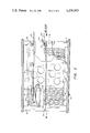
- FIG. 3 is a side view of a heating element assembly, incorporating the coil carrier illustrated in FIG. 1.
- the coil carrier illustrated in FIG. 1 comprises four rectangular fins 1 of similar width and length joined at right angles along their inner edges on a common center line.
- the respective end portions, 2 and 3, of the fins extend to the largest distance from the common center and serve to locate the element in a cylindrical air discharge duct D, FIG. 3, while the central edge portion between these ends, is slightly recessed.
- This portion of each fin is provided with a plurality of inwardly extending rectangular slots or notches 5 and 6, slots 5 being a shallow depth, while the slots 6 are deeper, as measured from the edge, i.e. the bottom of the slots 6 is nearer the carrier center than that of the slots 5.
- the slots are of equal width and equidistantly spaced by a common module denoted at 66, FIGS.
- a coil carrier comprises four fins 1 which are jointed at common center, all fins being of equal length and width, their end portions 2 and 3 being higher than the slotted center portion.
- the fins are perforated by a number of round holes 8 which serve to create greater flow turbulence, besides somewhat reducing the weight of the unit.
- Each fin edge is serrated along its recessed center portion by alternating shallower and deeper, rectangular slots 5 and 6 respectively.
- a heating coil is formed from a ribbon-shaped resistor laid successively into the slots 5 and 6 and wound around the coil carrier beginning from a L.H. terminal 20 to a R.H. terminal 21.
- the right hand end of the coil carrier is recessed (12) in its center corresponding to the shape of a fan motor to be positioned in this recess when assembling a hair dryer or another air heating apparatus.
- the coil terminal 20 is connected to a switch (not shown) by a cord 27 via a terminal 22 and through a fuse 23 and a thermistatic switch 24, while a second cord wire 28 is attached to the second coil terminal 21.
- a switch not shown
- a cord 27 via a terminal 22 and through a fuse 23 and a thermistatic switch 24, while a second cord wire 28 is attached to the second coil terminal 21.
- a portion of the coil is placed in the motor circuit in series with the motor, by means of an intermediate terminal or weld-top 25, the motor leads 26 and 27 issuing from the terminal 25 and the right hand terminal 21, respectively.
- FIG. 2 illustrated a coil carrier similar to that shown in FIG. 1 however it differs from the latter in that it has slots of three different depth dimensions, i.e. shallower slots 5, slots of medium depth (6) and of larger depth (7). It further differs from the former embodiment in that the coil carrier is in the shape of a pyramidal frustum, permitting its positioning in a conical duct, the remaining parts of the two carriers being identical.
- a ribbon-shaped resistor is wound around the coil carrier, its windings (10, 10' and 10") lying in three parallel planes.
- the main advantage of the present type of heating element lies in the fact that heat transfer is increased by preventing any boundary layer from being formed on a continuous plane, since the large air spaces between adjoining windings break up this formation and cause a turbulent air flow.
- the narrow front side of the ribbon exposed to the air flow presents very small flow resistance, thus permitting a small fan and fan motor to be installed in the appliance.
- the coil carrier having four fins is advantageous because it is readily assembled from two plates each corresponding in width to the width of two opposite fins; these plates are slotted along their center for half their length and nested by pushing them lengthwise together in cross fashion, in a manner known per se.
- more than three types of slots may be provided, especially in the case of large diameters and great lengths of the elements.
Abstract
An electric air heating element is designed for positioning in the cylindrical or conical outlet tube of a hair dryer. It consists of a star-shaped coil carrier in the shape of four fins extending radially from a common center line in the axis of the outlet tube towards the tube walls. The fin edges are serrated by adjacent rectangular slots, the slots on each edge penetrating alternately to a shallow and to a greater depth, and a ribbon-shaped resister laid into these slots is helically wound around the coil carrier. In this way successive windings lie in different planes and air turbulence around the heating coil is thereby increased, improving the heat transfer between the resistor windings and the throughflowing air.
Description
The invention relates to an electric heating element, particularly to an element suitable for hair dryers.
Heating elements for hair dryers should be as short as possible in order to reduce the weight of the appliance and to make it easy to handle; on the other hand it should present an adequate heat transfer surface while offering a minimum of flow resistance, with a view to permit the provision of a small fan and fan motor in the dryer. In the past I have found that the most suitable heating element answering the above requirements is in the shape of a ribbon-shaped resistor helically wound on a spider-shaped core, in such a manner that the ribbon surfaces of all windings are parallel to the air flow. This design ensures a minimum of flow resistance, since the front surface offered to the air flow by the thin resistor is very small compared with the total heat exchange area. A high heat exchange coefficient is attained by the air spaces between adjoining coil windings, because they interrupt the boundary layer apt to form along a plain continuous surfaces, and thus create air turbulence.
Although this type of heater coil gives very good results, I have now discovered that I can still improve the heat transfer by staggering successive windings and thus obtain a shorter total length of the element by providing less windings which, however, dissipate the same heat energy through a smaller exchange surface by virtue of increased turbulence.
The heating element which adapted to be positioned in a cylindrical of conical duct of a hair dryer or other apparatus delivering hot air, comprises a solid star-shaped coil-carrier of a non-conductive and heat-resistant material, in the shape of at least four longitudinal fins extending in radial direction from a common jointing line. The outer edges of all fins are serrated by substantially equidistant rectangular slots of different depth as measured from said outer edge of each fin, and a ribbon-shaped resistor is wound helically around said coil carrier to form a coil. The windings are laid in successive rectangular slots with the ribbon surface substantially parallel to the outer fin edge and to the air flow. The resulting coil thus comprises at least two parallel surfaces of resistor windings which, in the case of four fins, form at least two coaxial square cylinders or cylinder frustums. In a preferred embodiment of the heating element each fin edge is serrated by alternate slots of shallow depth and of greater depth respectively, thus forming two parallel layers of resistor windings.
In order to provide a larger distance between the coil and the duct walls both end portions of each fin are radially extended to a greater length than its serrated edge, which end portions serve to firmly secure the heating element in the duct or outlet of the air heating apparatus.
With a view to shorten the apparatus the center portion at one end of the coil carrier may be recessed to permit placing therein an electric fan motor, the resistor coil surrounding the motor at this end.
The ribs may be perforated in order to reduce the weight of the element and to increase the air turbulence.
FIG. 1 is an isometric view of a coil carrier, partly wound, suitable for a cylindrical duct,
FIG. 2 is an isometric view of a coil carrier provided with slots of three different depth dimensions, partly wound and suitable for a conical duct, and
FIG. 3 is a side view of a heating element assembly, incorporating the coil carrier illustrated in FIG. 1.
The coil carrier illustrated in FIG. 1 comprises four rectangular fins 1 of similar width and length joined at right angles along their inner edges on a common center line. The respective end portions, 2 and 3, of the fins extend to the largest distance from the common center and serve to locate the element in a cylindrical air discharge duct D, FIG. 3, while the central edge portion between these ends, is slightly recessed. This portion of each fin is provided with a plurality of inwardly extending rectangular slots or notches 5 and 6, slots 5 being a shallow depth, while the slots 6 are deeper, as measured from the edge, i.e. the bottom of the slots 6 is nearer the carrier center than that of the slots 5. The slots are of equal width and equidistantly spaced by a common module denoted at 66, FIGS. 1 and 2, however staggered by one quarter module in respect of every two fins positioned at a right angle, in one sense of angular progress, for the purpose of providing a helical path for the resistor ribbon. Four windings, 10 and 10', of a ribbon-shaped resistor are shown to be wound around the coil carrier, alternately laid in shallow and deep slots. The resistor is slightly narrower than the slots 5 and 6, and it can be readily discerned that the windings 10 laid in the shallow slots are of greater length than those (10') in the deeper slots, thus alternate windings in the shape of larger and smaller squares are being formed, corresponding sides of all larger squares lying in common planes, and similarly the sides of all smaller squares. It is understood that only a few windings have been such shown in order to present a clear picture of the slots. It is further understood that for clearness sake the size of the slots and the module are shown larger in proportion to the total dimensions of the coil carrier than in an actual embodiment, which would have a much larger number of windings.
A complete heating element is shown in FIG. 3. Herein a coil carrier comprises four fins 1 which are jointed at common center, all fins being of equal length and width, their end portions 2 and 3 being higher than the slotted center portion. The fins are perforated by a number of round holes 8 which serve to create greater flow turbulence, besides somewhat reducing the weight of the unit. Each fin edge is serrated along its recessed center portion by alternating shallower and deeper, rectangular slots 5 and 6 respectively. A heating coil is formed from a ribbon-shaped resistor laid successively into the slots 5 and 6 and wound around the coil carrier beginning from a L.H. terminal 20 to a R.H. terminal 21. The right hand end of the coil carrier is recessed (12) in its center corresponding to the shape of a fan motor to be positioned in this recess when assembling a hair dryer or another air heating apparatus.
The coil terminal 20 is connected to a switch (not shown) by a cord 27 via a terminal 22 and through a fuse 23 and a thermistatic switch 24, while a second cord wire 28 is attached to the second coil terminal 21. In order to reduce the motor voltage a portion of the coil is placed in the motor circuit in series with the motor, by means of an intermediate terminal or weld-top 25, the motor leads 26 and 27 issuing from the terminal 25 and the right hand terminal 21, respectively.
FIG. 2 illustrated a coil carrier similar to that shown in FIG. 1 however it differs from the latter in that it has slots of three different depth dimensions, i.e. shallower slots 5, slots of medium depth (6) and of larger depth (7). It further differs from the former embodiment in that the coil carrier is in the shape of a pyramidal frustum, permitting its positioning in a conical duct, the remaining parts of the two carriers being identical. A ribbon-shaped resistor is wound around the coil carrier, its windings (10, 10' and 10") lying in three parallel planes.
The main advantage of the present type of heating element lies in the fact that heat transfer is increased by preventing any boundary layer from being formed on a continuous plane, since the large air spaces between adjoining windings break up this formation and cause a turbulent air flow. On the other hand the narrow front side of the ribbon exposed to the air flow presents very small flow resistance, thus permitting a small fan and fan motor to be installed in the appliance.
Although only two embodiments of the air heating element have been described hereinbefore, it is understood that the invention may undergo various alterations and modifications to be carried out by a person skilled in the art, within the spirit of the invention and the scope of the appended claims.
It is, for instance proposed to provide any number of fins from a minimum of three to eight or more, the latter being suitable for a duct of large diameter as in industrial applications.
The coil carrier having four fins is advantageous because it is readily assembled from two plates each corresponding in width to the width of two opposite fins; these plates are slotted along their center for half their length and nested by pushing them lengthwise together in cross fashion, in a manner known per se.
In certain cases more than three types of slots may be provided, especially in the case of large diameters and great lengths of the elements.
Claims (6)
1. In combination, a tubular air discharge unit and heating element for a hair dryer, said element being positioned in said tubular air discharge duct in coaxial alignment therewith, said heating element comprising a solid coil-carrier of non-conductive and heat resistant material and including at least four longitudinal fins extending radially outwards from a common center line coinciding with the axis of such an air duct, said fins being of equal thickness and having the major extent of their outer edges serrated by inwardly extending substantially rectangularly shaped sets of notches of at least two different depths, said notches being equally spaced by a common spacing module and adjacent sets of notches having a different common depth so as to be intermittently higher and lower throughout such major extent of such outer edges, said notches being axially staggered by a quarter spacing module in respect of every two fins lying at right angles to one another to provide a helical path for resistor element, and a coil in the shape of a flat ribbon resistor wound helically around said coil carrier with the windings being laid successively in said notches with the ribbon lying in the bottom of the notches and extending parallel to the outer edges of the fins to provide intermittent layers in different parallel planes to provide high heat transfer with low flow resistance and to increase air turbulence around the said coil to facilitate breaking up the air boundary layer and providing at least one crossover of the ribbon.
2. An electric air heating element as defined in claim 1 wherein the fins are perforated by throughgoing holes to increase air turbulence.
3. An electric air heating element as defined in claim 1 wherein one end of the coil carrier is recessed in its center portion for the purpose of accomodating therein a portion or the whole of an electric fan motor.
4. An electric air heating element as defined in claim 1 wherein each outer fin edge is serrated by notches of three different depth dimensions.
5. An electric air heating element as defined in claim 1 including a multitude of weld-tops to create additional circuits.
6. An electric air heating element as defined in claim 5 where at least two weld-tops create an additional circuit.
Priority Applications (1)
| Application Number | Priority Date | Filing Date | Title |
|---|---|---|---|
| US05/878,945 US4230933A (en) | 1978-02-17 | 1978-02-17 | Electric air heating element |
Applications Claiming Priority (1)
| Application Number | Priority Date | Filing Date | Title |
|---|---|---|---|
| US05/878,945 US4230933A (en) | 1978-02-17 | 1978-02-17 | Electric air heating element |
Publications (1)
| Publication Number | Publication Date |
|---|---|
| US4230933A true US4230933A (en) | 1980-10-28 |
Family
ID=25373134
Family Applications (1)
| Application Number | Title | Priority Date | Filing Date |
|---|---|---|---|
| US05/878,945 Expired - Lifetime US4230933A (en) | 1978-02-17 | 1978-02-17 | Electric air heating element |
Country Status (1)
| Country | Link |
|---|---|
| US (1) | US4230933A (en) |
Cited By (13)
| Publication number | Priority date | Publication date | Assignee | Title |
|---|---|---|---|---|
| US4350872A (en) * | 1978-11-14 | 1982-09-21 | Firma Fritz Eichenauer | Electrical heating element for fluid media and method for producing same |
| US4357521A (en) * | 1978-07-12 | 1982-11-02 | Firma Fritz Eichenauer | Electrical heating device for fluid media |
| US6013903A (en) * | 1996-09-24 | 2000-01-11 | Mifune; Hideo | Flame reaction material carrier and method of manufacturing flame reaction member |
| EP0997914A2 (en) * | 1998-10-28 | 2000-05-03 | ABBPATENT GmbH | Electrical coil, especially for heating |
| US6137092A (en) * | 1998-10-22 | 2000-10-24 | I.R.C.A S.P.A.-Industria Resistenze Corazzate Affini | Resistance heating element, in particular for clothes dryers |
| US6732450B1 (en) * | 2003-07-11 | 2004-05-11 | Shu-Lien Chen | Electrothermal rack of hair dryer |
| US20040091250A1 (en) * | 2002-11-09 | 2004-05-13 | Jurgen Stritzinger | Heater for gaseous media |
| US20050194327A1 (en) * | 2004-03-05 | 2005-09-08 | Shu-Lien Chen | Positioning rack for thin-type electrothermal straps |
| US20080172900A1 (en) * | 2007-01-19 | 2008-07-24 | Carlos Jose Ceva | Halogen hair dryer |
| RU2499369C2 (en) * | 2012-01-11 | 2013-11-20 | Андрей Геннадьевич Черепков | Electric heater for running media |
| US9324482B1 (en) * | 2015-02-04 | 2016-04-26 | Elmatek Internation Corp. | High impedance resistor device applied in high voltage environment |
| USD758970S1 (en) | 2014-05-27 | 2016-06-14 | Vishay Dale Electronics, Llc | Edge-wound resistor |
| US9396847B2 (en) * | 2014-05-27 | 2016-07-19 | Vishay Dale Electronics, Llc | Edge-wound resistor, resistor assembly, and method of making same |
Citations (11)
| Publication number | Priority date | Publication date | Assignee | Title |
|---|---|---|---|---|
| US1490089A (en) * | 1921-09-28 | 1924-04-15 | Airdry Corp | Air heater |
| US1733023A (en) * | 1928-03-31 | 1929-10-22 | Kremenezky Johann | Adjustable high ohmic resistance and method of manufacturing same |
| US1840168A (en) * | 1929-04-30 | 1932-01-05 | Clarostat Mfg Company Inc | Ballast resistance |
| US2298315A (en) * | 1940-05-27 | 1942-10-13 | Siegel | Dummy antenna resistor |
| US2502044A (en) * | 1946-11-19 | 1950-03-28 | Herbert M Isaacson | Resistor support |
| US3304625A (en) * | 1964-05-25 | 1967-02-21 | Gen Electric | Portable hair dryer with heaters on both ends of flexible hose |
| US3391372A (en) * | 1966-05-16 | 1968-07-02 | Corning Glass Works | Electric heating unit |
| DE2015628A1 (en) * | 1970-04-02 | 1971-10-21 | Eichenauer Fa Fritz | Electric wire heating element |
| DE2608510A1 (en) * | 1976-03-02 | 1977-09-08 | Dov Z Glucksman | Tubular heating element with tape shaped resistor - has air blown over resistor tape wound along cross shaped former inside tube |
| DE2618819A1 (en) * | 1976-04-29 | 1977-11-17 | Dov Z Glucksman | Cylindrical or conical electric hair dryer - has motor driven axial flow fan discharging air coaxially through strip element winding |
| DE2619097A1 (en) * | 1976-05-03 | 1977-11-24 | Eichenauer Fa Fritz | Hair dryer electric heating element cord - consists of flexible glass formed core and helical surrounding conducting element |
-
1978
- 1978-02-17 US US05/878,945 patent/US4230933A/en not_active Expired - Lifetime
Patent Citations (11)
| Publication number | Priority date | Publication date | Assignee | Title |
|---|---|---|---|---|
| US1490089A (en) * | 1921-09-28 | 1924-04-15 | Airdry Corp | Air heater |
| US1733023A (en) * | 1928-03-31 | 1929-10-22 | Kremenezky Johann | Adjustable high ohmic resistance and method of manufacturing same |
| US1840168A (en) * | 1929-04-30 | 1932-01-05 | Clarostat Mfg Company Inc | Ballast resistance |
| US2298315A (en) * | 1940-05-27 | 1942-10-13 | Siegel | Dummy antenna resistor |
| US2502044A (en) * | 1946-11-19 | 1950-03-28 | Herbert M Isaacson | Resistor support |
| US3304625A (en) * | 1964-05-25 | 1967-02-21 | Gen Electric | Portable hair dryer with heaters on both ends of flexible hose |
| US3391372A (en) * | 1966-05-16 | 1968-07-02 | Corning Glass Works | Electric heating unit |
| DE2015628A1 (en) * | 1970-04-02 | 1971-10-21 | Eichenauer Fa Fritz | Electric wire heating element |
| DE2608510A1 (en) * | 1976-03-02 | 1977-09-08 | Dov Z Glucksman | Tubular heating element with tape shaped resistor - has air blown over resistor tape wound along cross shaped former inside tube |
| DE2618819A1 (en) * | 1976-04-29 | 1977-11-17 | Dov Z Glucksman | Cylindrical or conical electric hair dryer - has motor driven axial flow fan discharging air coaxially through strip element winding |
| DE2619097A1 (en) * | 1976-05-03 | 1977-11-24 | Eichenauer Fa Fritz | Hair dryer electric heating element cord - consists of flexible glass formed core and helical surrounding conducting element |
Cited By (16)
| Publication number | Priority date | Publication date | Assignee | Title |
|---|---|---|---|---|
| US4357521A (en) * | 1978-07-12 | 1982-11-02 | Firma Fritz Eichenauer | Electrical heating device for fluid media |
| US4350872A (en) * | 1978-11-14 | 1982-09-21 | Firma Fritz Eichenauer | Electrical heating element for fluid media and method for producing same |
| US6013903A (en) * | 1996-09-24 | 2000-01-11 | Mifune; Hideo | Flame reaction material carrier and method of manufacturing flame reaction member |
| US6137092A (en) * | 1998-10-22 | 2000-10-24 | I.R.C.A S.P.A.-Industria Resistenze Corazzate Affini | Resistance heating element, in particular for clothes dryers |
| EP0997914A2 (en) * | 1998-10-28 | 2000-05-03 | ABBPATENT GmbH | Electrical coil, especially for heating |
| EP0997914A3 (en) * | 1998-10-28 | 2003-10-08 | ABB PATENT GmbH | Electrical coil, especially for heating |
| US6864467B2 (en) * | 2002-11-09 | 2005-03-08 | Eichenauer Heizelemente Gmbh & Co. Kg | Heater for gaseous media |
| US20040091250A1 (en) * | 2002-11-09 | 2004-05-13 | Jurgen Stritzinger | Heater for gaseous media |
| US6732450B1 (en) * | 2003-07-11 | 2004-05-11 | Shu-Lien Chen | Electrothermal rack of hair dryer |
| US20050194327A1 (en) * | 2004-03-05 | 2005-09-08 | Shu-Lien Chen | Positioning rack for thin-type electrothermal straps |
| US20080172900A1 (en) * | 2007-01-19 | 2008-07-24 | Carlos Jose Ceva | Halogen hair dryer |
| RU2499369C2 (en) * | 2012-01-11 | 2013-11-20 | Андрей Геннадьевич Черепков | Electric heater for running media |
| USD758970S1 (en) | 2014-05-27 | 2016-06-14 | Vishay Dale Electronics, Llc | Edge-wound resistor |
| US9396847B2 (en) * | 2014-05-27 | 2016-07-19 | Vishay Dale Electronics, Llc | Edge-wound resistor, resistor assembly, and method of making same |
| USD855569S1 (en) | 2014-05-27 | 2019-08-06 | Vishay Dale Electronics, Llc | Edge-wound resistor |
| US9324482B1 (en) * | 2015-02-04 | 2016-04-26 | Elmatek Internation Corp. | High impedance resistor device applied in high voltage environment |
Similar Documents
| Publication | Publication Date | Title |
|---|---|---|
| US4230933A (en) | Electric air heating element | |
| JP4022067B2 (en) | Generator stator cooling device having a concave surface | |
| US3421578A (en) | Heat dissipator | |
| US3551643A (en) | Electric heater for heating fluids flowing longitudinally therethrough | |
| US3904851A (en) | Electric heater for heating a fluid medium | |
| IL46779A (en) | Electric air-heating element | |
| US5928549A (en) | Etched foil heater for low voltage applications requiring uniform heating | |
| US4272668A (en) | Small round air stream heating unit | |
| US4341946A (en) | Electrical resistance heating element | |
| GB2035710A (en) | Gas-cooled rotor for an electric machine | |
| FI75463C (en) | Electric heating device for heating a flow. | |
| US3360040A (en) | Heat exchanger elements | |
| US3965378A (en) | Pole coil for electric machines and apparatus | |
| US4357521A (en) | Electrical heating device for fluid media | |
| US4855571A (en) | Positive temperature coefficient ceramic heating element for heating a fluid | |
| US3214572A (en) | Electrical heater | |
| US2158601A (en) | Electrical heating apparatus and method of making the same | |
| CN201312395Y (en) | Tubular electromagnetic heating device | |
| US20180003409A1 (en) | Thermoelectric space heaters | |
| US2712053A (en) | Electric heating apparatus | |
| CN220173432U (en) | Fan heater winding structure and fan heating device | |
| US3534814A (en) | Heat exchanger construction | |
| CN209515353U (en) | A kind of screw type wire wound resistor | |
| US1170166A (en) | Electrical heating unit. | |
| ITMI981324A1 (en) | SERIES OF SELF-HEATING FANS FOR HOT AIR CONVEYORS WITH ROTATING FAN |