US4215919A - Refractor optical system - Google Patents

Refractor optical system Download PDF

Info

Publication number
US4215919A
US4215919A US05/894,455 US89445578A US4215919A US 4215919 A US4215919 A US 4215919A US 89445578 A US89445578 A US 89445578A US 4215919 A US4215919 A US 4215919A
Authority
US
United States
Prior art keywords
lens
lenses
sphere
cylinder
dial
Prior art date
Legal status (The legal status is an assumption and is not a legal conclusion. Google has not performed a legal analysis and makes no representation as to the accuracy of the status listed.)
Expired - Lifetime
Application number
US05/894,455
Inventor
Edward B. Rybicki
Current Assignee (The listed assignees may be inaccurate. Google has not performed a legal analysis and makes no representation or warranty as to the accuracy of the list.)
Leica Microsystems Inc
Original Assignee
American Optical Corp
Priority date (The priority date is an assumption and is not a legal conclusion. Google has not performed a legal analysis and makes no representation as to the accuracy of the date listed.)
Filing date
Publication date
Application filed by American Optical Corp filed Critical American Optical Corp
Priority to US05/894,455 priority Critical patent/US4215919A/en
Priority to CA324,311A priority patent/CA1112924A/en
Priority to AU45627/79A priority patent/AU521562B2/en
Priority to DE19792913001 priority patent/DE2913001A1/en
Priority to GB7911637A priority patent/GB2018461B/en
Priority to NL7902639A priority patent/NL7902639A/en
Priority to BR7902138A priority patent/BR7902138A/en
Priority to JP4115379A priority patent/JPS54139745A/en
Priority to FR7908719A priority patent/FR2421592A1/en
Priority to CH325379A priority patent/CH642530A5/en
Priority to US06/134,374 priority patent/US4413891A/en
Publication of US4215919A publication Critical patent/US4215919A/en
Application granted granted Critical
Priority to CA368,069A priority patent/CA1128794A/en
Assigned to WARNER LAMBERT TECHNOLOGIES, INC., A CORP OF TX. reassignment WARNER LAMBERT TECHNOLOGIES, INC., A CORP OF TX. ASSIGNMENT OF ASSIGNORS INTEREST. Assignors: WARNER LAMBERT COMPANY
Assigned to WARNER LAMBERT COMPANY, A CORP. OF DEL. reassignment WARNER LAMBERT COMPANY, A CORP. OF DEL. ASSIGNMENT OF ASSIGNORS INTEREST. Assignors: AMERICAN OPTICAL CORPORATION,
Priority to HK180/85A priority patent/HK18085A/en
Assigned to CAMBRIDGE INSTRUMENTS INC., A DE CORP. reassignment CAMBRIDGE INSTRUMENTS INC., A DE CORP. ASSIGNMENT OF ASSIGNORS INTEREST. Assignors: WARNER LAMBERT TECHNOLOGIES, INC.
Anticipated expiration legal-status Critical
Expired - Lifetime legal-status Critical Current

Links

Images

Classifications

    • AHUMAN NECESSITIES
    • A61MEDICAL OR VETERINARY SCIENCE; HYGIENE
    • A61BDIAGNOSIS; SURGERY; IDENTIFICATION
    • A61B3/00Apparatus for testing the eyes; Instruments for examining the eyes
    • A61B3/10Objective types, i.e. instruments for examining the eyes independent of the patients' perceptions or reactions
    • A61B3/12Objective types, i.e. instruments for examining the eyes independent of the patients' perceptions or reactions for looking at the eye fundus, e.g. ophthalmoscopes

Definitions

  • This invention relates to refractor optical systems and, more particularly, to a spherical and a cylinderical lens series for a refractor having regular additive errors to permit non-additive combinations for correction of additive error.
  • Refractors are well known ophthalmic instruments used for determining the proper lens value necessary to correct the defective vision of a patient.
  • the refractor typically includes a right hand battery and a left hand battery, each for enabling the practitioner to place various corrective lenses in alignment with a respective patient's eye.
  • Each of the batteries is alike and each includes a series of spherical lenses and series of cylindrical lenses.
  • the spherical lens assembly and the cylindrical lens assembly each conventionally include a pair of discs. One of each pair of discs contains lenses having a "weak" power in incremental increases of power and the other disc of each pair contains lenses having "strong" power.
  • the lenses of the "strong" power disc are of sequentially increasing power with the increments of increasing power usually at least being equal to the highest power of the corresponding "weak” lens plus the "weak” lens increment.
  • the practitioner may rotate one of the lenses in each disc into alignment with the patient's eye. In early refractors, like trial lens sets, the practitioner could select the particular combination of lenses which he wished to place before the patient's eyes.
  • Each lens was manufactured to have a specific power whether the lens was used by itself or in combination with one or more other lenses. For example, to provide a cylinder power of plus 6.50 diopters, the practitioner would select the +6.0 diopter sphere lens and the +0.5 diopter cylinder lens.
  • additive error refers to the difference between the real cylinder power of a lens combination and the power expected from the sum of the powers of the individual cylinder lenses in the combination.
  • significant additive error is used herein to denote additive error in excess of 0.1 diopter.
  • the disc containing the "weak” lenses were mechanically coupled to the disc containing the "strong” lenses. This permitted the practitioner to operate a single control to vary the spherical power presented to the eye and similarly a single control to vary the cylinder power presented to the eye.
  • the constrictions placed upon lens design were even more severe in such instruments because the mechanical linkage used to couple the cylinder lens discs prevents the practitioner from personally selecting individual lens combinations.
  • U.S. Pat. No. 2,266,797 issued Dec. 23, 1941 to Peck et al discloses an early refractor in which lenses in the "weak” lens disc were not mechanically coupled to lenses in the "strong” lens disc.
  • the Patent further discloses the manner in which the various lens power in individual discs are combined to provide the resultant power desired by the practitioner.
  • one object of the described invention is to provide a "cooperatively functioning series of lenses computed as to curvatures and thicknesses, distance between lenses of said series and position of said lenses before the eye"
  • the patent contains no description of the lens series by or means for determining the lens series.
  • a refractor singlet lens series where all lenses presented at the reference plane (called the A lenses) have the same glass, the same thickness, one surface having the same radius and the same spacings to the next combined lens, will not change the additive error for a combination of three or more lenses when the A lens of the combination is changed. It is understood that, if the series of A lenses contains a zero power position, this position must have a zero power lens meeting the same requirements as any other A lens. Since the amount of significant additive error remains unchanged in spite of changes in the A lenses, the number of different corrections in all possible lens combinations which must be calculated or are required is reduced by a factor equal to the number of A lenses. Although the constant radius of the A lenses need not be infinity, a planar surface is preferred since the planar surface reduces the problems associated with constructing a zero power lens (window) to a minimum.
  • the preferred embodiment is arranged with the strong sphere dial located at the reference plane and has a series of lenses of identical center thickness, identical glass, and a planar surface on the side of the lenses furthest from the patient's eye. Such a lens series will provide identical error for each combination of cylinder lenses in every position of the strong sphere dial.
  • the radius of the surface closest to the eye must be individually determined for each lens based upon the spacing of the lens from the eye and the power desired. While not constant, the radii for all lenses in a single dial will be related, since the spacing thickness and index of refraction for all lenses in that dial are identical.
  • the lens series of the present invention when incorporated into a refractor reduces the prior art additive cylinder errors in a refractor having 12 positions of the strong sphere dial by a factor of 12 and provides 100% predictability of the occurrence of significant additive errors since every position of the strong sphere dial has identical errors.
  • the drawing is an optical diagram illustrating the position of representative lenses in a refractor having a lens series of the present invention.
  • the lenses in the strong sphere disc of a refractor are identified by I and have variable radius R 1 .1 to R 1 .12.
  • the lenses in the weak sphere dial are represented by the lens identified by II and have radii of R 2 .1 to R 2 .12.
  • strong cylinder lenses are represented by the lens identified III and have individual radii identified as R 3 .1 to R 3 .12
  • weak cylinder lenses represented by the lens identified by IV and have respective radii R 4 .1 to R 4 .6.
  • An auxiliary dial in a refractor is frequently used to carry special optical elements for conducting certain tests during refraction.
  • the optical elements are represented by lens V and preferably include 0.125 diopter auxiliary sphere lens.
  • the lenses have radii R 5 .1 to R 5 .2.
  • Refractors frequently have window VI in order to keep dust and dirt from the interior mechanism and optical surfaces.
  • the distance from the optical surface furthest from the eye of the various elements to the reference plane are identified as D1 to D5 for the weak cylinder lenses, strong cylinder lenses, auxiliary lenses, weak sphere lenses and strong sphere lenses, respectively.
  • the distance from the reference plane to the window and to the patient's eye are respectively identified as D6 and D7.
  • All lenses including the window and auxiliary lens are made of a glass having an index of refraction of 1.523, an Abbe number of 58.6 and a thickness of 1.6 millimeters.
  • the index of refraction of the lenses may be varied by ⁇ 0.0005, Abbe number ⁇ 0.5 and thickness (except the auxiliary lens) by ⁇ 0.2 millimeter. While zero power position in the weak sphere, strong cylinder, weak cylinder and auxiliary dials is an open aperture, the strong sphere disc has a planar plate of the same glass and thickness as the lenses. This plate has a radius identified as infinity in the table, while zero diopter positions in other discs are noted as having a zero radius since no glass is present.
  • Those radii, calculated and actual which are 0.00 identify open apertures in the respective discs. dials.
  • the lens having radius R 3 .7 has a planar surface on both sides as indicated by the calculated and actual radius of infinity. All the radii are in millimeters and a minus sign (-) denotes a radius having a center on the side of the lens away from the patient's eye.
  • a refractor having a lens series with the foregoing values will exhibit deviation at far point testing (20 ft.) from the marked additive powers only in those positions shown in Table II.
  • Corrections of +0.125 cylinder diopter for these deviations in marked cylinder power are made by changing the cylinder power for those positions of the weak sphere dial presenting a negative sphere power. For example, when the cylinder power is 8.25; and the weak sphere lens in position 1 of dial II (-1.00 diopter) and auxiliary dial V in position 2(+0.125 diopter) on the test axes the correction would be made by increasing the cylinder power from 8.25 to 8.38.
  • the cylinder power would be reduced by 0.125 diopter.
  • the cylinder power is 6.63
  • the weak sphere lens in position 9 of dial II (+1.00 diopter) and auxiliary dial V in position 1 (0.0 diopter) are on the test axis
  • correction would be made by reducing the cylinder power from 6.63 to 6.50.
  • the error for any combination of cylinder and spherical lenses is less than ⁇ 0.10 cylinder diopters. In fact, for those combinations which have been corrected, the error is reduced to not more than 0.075 diopters.
  • Table III presents the error range at near point testing (16 in.) for all combinations of the strong cylinder dial III and weak cylinder dial IV with the weak sphere dial II and auxiliary dial V when the strong sphere dial I is in the zero power position (position 7). As can be seen in Table III the number combinations having error and the amount of error in many combinations is substantially larger than the additive errors encountered during far point testing.
  • the cylinder error can be reduced to less than a tenth of a diopter for all but a few cylinder lens combinations.
  • the cylinder lens combinations after adjustment are shown in Table IV with the range of error associated with each combination. Note that only the very high combinations (over 8.25 diopters of cylinder) result in any error for near point because it is not possible to provide the necessary substantial increases by adjustment since the maximum cylinder power of any combination is 8.75. This explains the substantial cylinder error in the localized region shown by Table IV following adjustment.
  • Table V provides the location and type of cylinder power adjustment required for each combination of cylinder lenses. These adjustments are made for each combination which requires adjustment in the same manner as the adjustments described of negative sphere powers for far point testing.
  • Table VI is representative of the amount of cylinder error, at near point, and shows the precise amount of spherical and cylinder error for each combination of the weak cylinder dial IV with the strong cylinder dial III when the spherical power is zero.
  • Table VII presents the amount of cylinder error for several cylinder powers and varying positions of strong sphere dial I. Note that while the amount of error varies with various cylinder powers, the error remains identical through the entire range from -18 to +15.250 diopters of sphere for that cylinder power so long as the weak sphere dial II and/or auxiliary dial V are not changed.

Abstract

A refractor optical system having a new series of spherical and cylinder lenses substantially eliminates the irregular occurrence of additive errors when lenses spaced from the reference plane are used or more than two lenses are combined and permits correction for the significant additive errors by non-additive lens selection.

Description

BACKGROUND OF THE INVENTION
This invention relates to refractor optical systems and, more particularly, to a spherical and a cylinderical lens series for a refractor having regular additive errors to permit non-additive combinations for correction of additive error.
Refractors are well known ophthalmic instruments used for determining the proper lens value necessary to correct the defective vision of a patient. The refractor typically includes a right hand battery and a left hand battery, each for enabling the practitioner to place various corrective lenses in alignment with a respective patient's eye. Each of the batteries is alike and each includes a series of spherical lenses and series of cylindrical lenses. The spherical lens assembly and the cylindrical lens assembly each conventionally include a pair of discs. One of each pair of discs contains lenses having a "weak" power in incremental increases of power and the other disc of each pair contains lenses having "strong" power. The lenses of the "strong" power disc are of sequentially increasing power with the increments of increasing power usually at least being equal to the highest power of the corresponding "weak" lens plus the "weak" lens increment. The practitioner may rotate one of the lenses in each disc into alignment with the patient's eye. In early refractors, like trial lens sets, the practitioner could select the particular combination of lenses which he wished to place before the patient's eyes. Each lens was manufactured to have a specific power whether the lens was used by itself or in combination with one or more other lenses. For example, to provide a cylinder power of plus 6.50 diopters, the practitioner would select the +6.0 diopter sphere lens and the +0.5 diopter cylinder lens. In lens series of such prior art devices, the designer attempted to minimize the error in any particular combination since each lens, for example the +0.25 diopter cylinder lens, was used any time the practitioner needed to add 0.25 diopter of cylinder. In the average trial lens sets there are over three thousand lens combinations in which the 0.25 diopter cylinder lens may be used. Since the only way to correct for additive error was to refer to a reference chart which covered all the permutations of lens combinations, the lens designer attempted to minimize the error resulting from combining lenses in each possible combination of the series.
As used hereinafter, the term "additive error" refers to the difference between the real cylinder power of a lens combination and the power expected from the sum of the powers of the individual cylinder lenses in the combination. The term "significant" additive error is used herein to denote additive error in excess of 0.1 diopter.
As refractors developed and became more refined, the disc containing the "weak" lenses were mechanically coupled to the disc containing the "strong" lenses. This permitted the practitioner to operate a single control to vary the spherical power presented to the eye and similarly a single control to vary the cylinder power presented to the eye. The constrictions placed upon lens design were even more severe in such instruments because the mechanical linkage used to couple the cylinder lens discs prevents the practitioner from personally selecting individual lens combinations.
PRIOR ART
U.S. Pat. No. 1,455,457, issued May 15, 1923 to Tillyer, discloses a "new" series of test lenses which minimizes additive error when more than one lens is used. This patent describes the defects of the prior art and teaches that the minimization of the amount of error when combining lenses is important. The lens series is not designed to provide the least number of errors or predictable combinations which have significant error.
U.S. Pat. No. 2,266,797 issued Dec. 23, 1941 to Peck et al, discloses an early refractor in which lenses in the "weak" lens disc were not mechanically coupled to lenses in the "strong" lens disc. The Patent further discloses the manner in which the various lens power in individual discs are combined to provide the resultant power desired by the practitioner. Although one object of the described invention is to provide a "cooperatively functioning series of lenses computed as to curvatures and thicknesses, distance between lenses of said series and position of said lenses before the eye", the patent contains no description of the lens series by or means for determining the lens series. AMERICAN JOURNAL OF OPTOMETRY AND PHYSIOLOGICAL OPTICS, Volume 52 Pages 533-540 (August, 1975) presents a reprint of a paper read at the American Academy of Optometry Annual Meeting in December of 1974, entitled Additive Lens Systems in Eye Refractors. The paper evaluates the lens series of the 1923 Tillyer Patent and establishes that the series is correct for only two lenses in combination. The paper further points out that additional lenses can cause additive error in excess of 0.5 diopter. In conclusion, the paper finds that a programmable desk top calculator, a computer actuated eye refractor, or a micro computer are required to present a plurality of lenses without additive error or convert the lenses actually presented to real power when printing out the prescription.
It is an object of the present invention to overcome the deficiencies and inadequacies of the prior art.
It is another object of the present invention to provide a lens series for use in a refractor having predictable combinations of lenses, which produce significant additive error.
It is still another object of the present invention to provide a lens series in which additive error of every combination of cylinder lenses is identical for all lenses of the strong sphere dial including the zero power plate.
BRIEF DESCRIPTION OF THE INVENTION AND DRAWINGS
A refractor singlet lens series, where all lenses presented at the reference plane (called the A lenses) have the same glass, the same thickness, one surface having the same radius and the same spacings to the next combined lens, will not change the additive error for a combination of three or more lenses when the A lens of the combination is changed. It is understood that, if the series of A lenses contains a zero power position, this position must have a zero power lens meeting the same requirements as any other A lens. Since the amount of significant additive error remains unchanged in spite of changes in the A lenses, the number of different corrections in all possible lens combinations which must be calculated or are required is reduced by a factor equal to the number of A lenses. Although the constant radius of the A lenses need not be infinity, a planar surface is preferred since the planar surface reduces the problems associated with constructing a zero power lens (window) to a minimum.
In a refractor having weak sphere lenses, strong sphere lenses, weak cylinder lenses, and strong cylinder lenses, each respectively carried by a rotatable dial to permit a selected one of each group of lenses to be placed before a patient's eye, the preferred embodiment is arranged with the strong sphere dial located at the reference plane and has a series of lenses of identical center thickness, identical glass, and a planar surface on the side of the lenses furthest from the patient's eye. Such a lens series will provide identical error for each combination of cylinder lenses in every position of the strong sphere dial.
The radius of the surface closest to the eye, must be individually determined for each lens based upon the spacing of the lens from the eye and the power desired. While not constant, the radii for all lenses in a single dial will be related, since the spacing thickness and index of refraction for all lenses in that dial are identical. The lens series of the present invention when incorporated into a refractor reduces the prior art additive cylinder errors in a refractor having 12 positions of the strong sphere dial by a factor of 12 and provides 100% predictability of the occurrence of significant additive errors since every position of the strong sphere dial has identical errors.
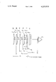
The drawing is an optical diagram illustrating the position of representative lenses in a refractor having a lens series of the present invention.
DETAILED DESCRIPTION OF THE INVENTION AND PREFERRED EMBODIMENT
Referring to FIG. 1, the lenses in the strong sphere disc of a refractor are identified by I and have variable radius R1.1 to R1.12. The lenses in the weak sphere dial are represented by the lens identified by II and have radii of R2.1 to R2.12. Similarly, strong cylinder lenses are represented by the lens identified III and have individual radii identified as R3.1 to R3.12 and weak cylinder lenses represented by the lens identified by IV and have respective radii R4.1 to R4.6. An auxiliary dial in a refractor is frequently used to carry special optical elements for conducting certain tests during refraction. The optical elements are represented by lens V and preferably include 0.125 diopter auxiliary sphere lens. The lenses have radii R5.1 to R5.2. Refractors frequently have window VI in order to keep dust and dirt from the interior mechanism and optical surfaces. The distance from the optical surface furthest from the eye of the various elements to the reference plane are identified as D1 to D5 for the weak cylinder lenses, strong cylinder lenses, auxiliary lenses, weak sphere lenses and strong sphere lenses, respectively. The distance from the reference plane to the window and to the patient's eye are respectively identified as D6 and D7. All lenses including the window and auxiliary lens are made of a glass having an index of refraction of 1.523, an Abbe number of 58.6 and a thickness of 1.6 millimeters. The index of refraction of the lenses may be varied by ±0.0005, Abbe number ±0.5 and thickness (except the auxiliary lens) by ±0.2 millimeter. While zero power position in the weak sphere, strong cylinder, weak cylinder and auxiliary dials is an open aperture, the strong sphere disc has a planar plate of the same glass and thickness as the lenses. This plate has a radius identified as infinity in the table, while zero diopter positions in other discs are noted as having a zero radius since no glass is present.
Since all lenses have an identical center thickness of 1.6 mm, the spacing between lenses of adjacent dials will be identical regardless of which lens in either dial is positioned before the eye. For the lens series of the preferred embodiment S1 is 2.368, S2 is 2.877, S3 is 2.368 and S4 is 2.368 mm. The distances identified in the drawing are D1=17.981, D2=14.013, D3=9.536, D4=5.568, D5=1.6, D6=1.57, and D7=14.27 mm. Table I provides the marked power, real power, calculated radius and actual radius of the variable surface for each lens of respective dials I-IV and the one lens of auxiliary dial V. Those radii, calculated and actual which are 0.00 identify open apertures in the respective discs. dials. The lens having radius R3.7 has a planar surface on both sides as indicated by the calculated and actual radius of infinity. All the radii are in millimeters and a minus sign (-) denotes a radius having a center on the side of the lens away from the patient's eye.
                                  TABLE I                                 
__________________________________________________________________________
         MARKED                                                           
               REAL CALCULATED                                            
                             ACTUAL                                       
POSITION                                                                  
      NO.                                                                 
         POWER POWER                                                      
                    RADIUS   RADIUS                                       
__________________________________________________________________________
STRONG CYLINDRICAL POWERS (DIAL III)                                      
1     .sup.R 3.1                                                          
         0.0   0.0  0.0      0.0                                          
2     3.2                                                                 
         0.750 0.743                                                      
                    703.53797                                             
                             703.538                                      
3     3.3                                                                 
         1.500 1.474                                                      
                    354.87131                                             
                             354.871                                      
4     3.4                                                                 
         2.250 2.192                                                      
                    238.64909                                             
                             238.649                                      
5     3.5                                                                 
         3.000 2.897                                                      
                    180.53797                                             
                             180.538                                      
6     3.6                                                                 
         3.750 3.590                                                      
                    145.67131                                             
                             145.671                                      
7     3.7                                                                 
         4.500 4.272                                                      
                    122.42686                                             
                             122.427                                      
8     3.8                                                                 
         5.250 4.942                                                      
                    105.82369                                             
                             105.824                                      
9     3.9                                                                 
         6.000 5.601                                                      
                    93.37131 93.371                                       
10    3.10                                                                
         6.750 6.250                                                      
                    83.68612 83.686                                       
11    3.11                                                                
         7.500 6.887                                                      
                    75.93797 75.938                                       
12    3.12                                                                
         8.250 7.515                                                      
                    69.59858 69.599                                       
__________________________________________________________________________
WEAK CYLINDRICAL POWERS (DIAL IV)                                         
1     .sup.R 4.1                                                          
         0.0   0.0  0.0      0.0                                          
2     4.2                                                                 
         0.125 0.125                                                      
                    4192.27990                                            
                             4192.280                                     
3     4.3                                                                 
         0.250 0.249                                                      
                    2100.27990                                            
                             2100.280                                     
4     4.4                                                                 
         0.375 0.373                                                      
                    1402.94657                                            
                             1402.947                                     
5     4.5                                                                 
         0.500 0.496                                                      
                    1054.27990                                            
                             1054.280                                     
6     4.6                                                                 
         0.625 0.619                                                      
                    845.07990                                             
                             845.080                                      
__________________________________________________________________________
STRONG SPHERICAL POWERS (DIAL I)                                          
1     .sup.R 1.1                                                          
         -18.000                                                          
               -18.000                                                    
                    -29.05556                                             
                             -29.056                                      
2     1.2                                                                 
         -15.000                                                          
               -15.000                                                    
                    -34.86667                                             
                             -34.867                                      
3     1.3                                                                 
         -12.000                                                          
               -12.000                                                    
                    -43.58333                                             
                             -43.583                                      
4     1.4                                                                 
         -9.000                                                           
               -9.000                                                     
                    -58.11111                                             
                             -58.111                                      
5     1.5                                                                 
         -6.000                                                           
               -6.000                                                     
                    -87.16667                                             
                             -87.167                                      
6     1.6                                                                 
         -3.000                                                           
               -3.000                                                     
                    -174.33333                                            
                             -174.333                                     
7     1.7                                                                 
         0.0   0.000                                                      
                    ∞  ∞                                      
8     1.8                                                                 
         3.000 3.000                                                      
                    174.33333                                             
                             174.333                                      
9     1.9                                                                 
         6.000 6.000                                                      
                    87.16667 87.167                                       
10    1.10                                                                
         9.000 9.000                                                      
                    58.11111 58.111                                       
11    1.11                                                                
         12.000                                                           
               12.000                                                     
                    43.58333 43.583                                       
12    1.12                                                                
         15.000                                                           
               15.000                                                     
                    34.86667 34.867                                       
__________________________________________________________________________
WEAK SPHERICAL POWERS (DIAL II)                                           
1     .sup.R 2.1                                                          
         -1.000                                                           
               -1.003                                                     
                    -521.21209                                            
                             -521.212                                     
2     2.2                                                                 
         -0.750                                                           
               -0.752                                                     
                    -695.654543                                           
                             -695.545                                     
3     2.3                                                                 
         -0.500                                                           
               -0.501                                                     
                    -1044.21209                                           
                             -1044.212                                    
4     2.4                                                                 
         -0.250                                                           
               -0.250                                                     
                    -2090.21209                                           
                             -2090.212                                    
5     2.5                                                                 
         0.0   0.0  0.0      0.0                                          
6     2.6                                                                 
         0.250 0.250                                                      
                    2093.78791                                            
                             2093.788                                     
7     2.7                                                                 
         0.500 0.499                                                      
                    1047.78791                                            
                             1047.788                                     
8     2.8                                                                 
         0.750 0.748                                                      
                    699.12124                                             
                             699.121                                      
9     2.9                                                                 
         1.000 0.997                                                      
                    542.78791                                             
                             524.788                                      
10    2.10                                                                
         1.250 1.245                                                      
                    420.18791                                             
                             420.188                                      
11    2.11                                                                
         1.500 1.492                                                      
                    350.45457                                             
                             350.455                                      
12    2.12                                                                
         1.750 1.740                                                      
                    300.64505                                             
                             300.645                                      
__________________________________________________________________________
AUXILIARY SPHERICAL POWERS (DIAL V)                                       
1     .sup.R 5.1                                                          
         0.0   0.0  0.0      0.0                                          
2     5.2                                                                 
         0.125 0.125                                                      
                    4187.86317                                            
                             4187.86317                                   
__________________________________________________________________________
A refractor having a lens series with the foregoing values will exhibit deviation at far point testing (20 ft.) from the marked additive powers only in those positions shown in Table II. Corrections of +0.125 cylinder diopter for these deviations in marked cylinder power are made by changing the cylinder power for those positions of the weak sphere dial presenting a negative sphere power. For example, when the cylinder power is 8.25; and the weak sphere lens in position 1 of dial II (-1.00 diopter) and auxiliary dial V in position 2(+0.125 diopter) on the test axes the correction would be made by increasing the cylinder power from 8.25 to 8.38. Similarly, for those positions of dial II having a spherical power of 0 or greater, the cylinder power would be reduced by 0.125 diopter. For example, when the cylinder power is 6.63, and the weak sphere lens in position 9 of dial II (+1.00 diopter) and auxiliary dial V in position 1 (0.0 diopter) are on the test axis, correction would be made by reducing the cylinder power from 6.63 to 6.50. When the lens combinations for far point testing are adjusted as indicated above, the error for any combination of cylinder and spherical lenses is less than ±0.10 cylinder diopters. In fact, for those combinations which have been corrected, the error is reduced to not more than 0.075 diopters. Since the errors occurring in any position of the strong sphere dial I are the same as the errors occurring in any other position of strong sphere dial I, the adjustments which are provided for the zero position (position 7) of strong sphere dial I are used in all other positions of the strong sphere dial.
TABLE II
  STRONG WEAK                SPHERE SPHERE AUXILIARY 01  02  03  04  05
 06  07  08  09  10  11  12  STRONG CYL. (III) (I) (II) (V) 123456 123456
 123456 123456 123456 123456 123456 123456 123456 123456 123456 123456
 WEAK CYL. (IV)
   7 1 1        -1.00  7 1 2       * -0.88 7 2 1        -0.75 7 2 2
 * -0.63 7 3 1        -0.50 7 3 2        -0.38 7 4 1        -0.25 7 4 2
      -0.13 7 5 1     * * ** 0.0  7 5 2       * 0.13 7 6 1        0.25 7
 6 2        0.38 SPHERE 7 7 1      * * 0.50 POWER 7 7 2        0.63 7 8 1
    * * * ** 0.75 7 8 2       * 0.88 7 9 1   * * ** ** ** 1.00 7 9 2    *
 * * * 1.13 7 10 1   * ** ** *** *** 1.25 7 10 2   * * ** ** ** 1.38 7 11
 1  * ** ** *** *** **** 1.50 7 11 2  * * ** ** ** ** 1.63 7 12 1  ** **
 *** *** **** **** 1.75 7 12 2  * ** ** *** *** *** 1.88 0.01.02.03.04.05.
 06.07.08.09.0 CYLINDER POWER  ERROR RANGE (DIOPTERS) SYMBOL   FAR POINT
 ERRORS E ≦ 0.10 BLANK (BEFORE ADJUSTMENT) 0.10 < E ≦ 0.25
 *
Table III presents the error range at near point testing (16 in.) for all combinations of the strong cylinder dial III and weak cylinder dial IV with the weak sphere dial II and auxiliary dial V when the strong sphere dial I is in the zero power position (position 7). As can be seen in Table III the number combinations having error and the amount of error in many combinations is substantially larger than the additive errors encountered during far point testing.
TABLE III
  STRONG WEAK AUXIL-               SPHERE SPHERE IARY 01  02  03  04  05
 06  07  08  09  10  11  12  STRONG CYL. (III) (I) (II) (V) 123456 123456
 123456 123456 123456 123456 123456 123456 123456 123456 123456 123456
 WEAK CYL. (IV)
   7 1 1  ***** ****** ****** ****** ###### ###### ###### ###### x#####
 xxxxxx -1.00  7 1 2  **** ****** ****** ****** ###### ###### ######
 ###### x##### xxxxxx -0.88 7 2 1  **** ****** ****** ****** ######
 ###### ###### ###### ###### xxxxx# -0.75 7 2 2  *** ****** ****** ******
 ###### ###### ###### ###### ###### xxxxx# -0.63 7 3 1  **** ******
 ****** ****** ###### ###### ###### ###### ###### xxxx## -0.50 7 3 2  ***
 ****** ****** ****** ###### ###### ###### ###### ###### xxxx## -0.38 7 4
 1  *** ****** ****** ****** ###### # ##### ###### ###### ###### xx####
 -0.25 7 4 2  ** ****** ****** ****** ###### ###### ###### ###### ######
 xx#### -0.13 7 5 1  *** ****** ****** ****** ###### ###### ###### ######
 ###### ###### 0.0  7 5 2  ** ****** ****** ****** ###*** ###### ######
 ###### ###### ###### 0.13 7 6 1  ** ****** ****** ****** ###*** #### ##
 ###### ###### ###### ###### 0.25 7 6 2  * ****** ****** ****** ******
 ###### ###### ###### ###### ###### 0.38 SPHERE 7 7 1  * ****** ******
 ****** #***** ###### ###### ###### ###### ###### 0.50 POWER 7 7 2
 ****** ****** ****** ****** ###### ###### ###### ###### ###### 0.63 7 8
 1  * ****** ****** ****** ****** ###### ###### ###### ###### ###### 0.75
 7 8 2   ****** ****** ****** ****** ###### ###### ###### ###### ######
 0.88 7 9 1   ****** ****** ****** ****** ###### ###### ###### ######
 ###### 1.00 7 9 2   ****** ****** ****** ****** ####** ###### ###########
 # ###### 1.13 7 10 1   ****** ****** ****** ****** ####** ###### ######
 ###### ###### 1.25 7 10 2   ****** ****** ****** ****** ##**** ##### #
 ###### ###### ###### 1.38 7 11 1   ****** ****** ****** ****** ##****
 ###### ###### ###### ###### 1.50 7 11 2   ***** ****** ****** ******
 #***** ###### ###### ###### ###### 1.63 7 12 1   ****** ****** ******
 ****** #***** ###### ###### ###### ###### 1.75 7 12 2   *** ******
 ****** ****** ****** #####* ###### ###### ###### 1.88 0.01.02.03.04.05.06
 .07.08.09.0  ERROR RANGE (DIOPTERS) SYMBOL  NEAR POINT ERRORS E ≦
 0.10 BLANK (BEFORE ADJUSTMENT) 0.10 < E ≦ 0.25 *  0.25 < E
 ≦ 0.50 #  0.50 <
  E x
After adjustments, the cylinder error can be reduced to less than a tenth of a diopter for all but a few cylinder lens combinations. The cylinder lens combinations after adjustment are shown in Table IV with the range of error associated with each combination. Note that only the very high combinations (over 8.25 diopters of cylinder) result in any error for near point because it is not possible to provide the necessary substantial increases by adjustment since the maximum cylinder power of any combination is 8.75. This explains the substantial cylinder error in the localized region shown by Table IV following adjustment. Table V provides the location and type of cylinder power adjustment required for each combination of cylinder lenses. These adjustments are made for each combination which requires adjustment in the same manner as the adjustments described of negative sphere powers for far point testing.
TABLE IV
  STRONG WEAK               SPHERE SPHERE AUXILIARY 01  02  03  04  05
 06  07  08  09  10  11  12  STRONG CYC. (III) (I) (II) (V) 123456 123456
 123456 123456 123456 123456 123456 123456 123456 123456 123456 123456
 WEAK CYL. (IV)
   7 1 1  xxxx -1.00  7 1 2  xxxx -0.88 7 2 1  #xxx -0.75 7 2 2  #xxx
 -0.63 7 3 1  *xxx -0.50 7 3 2  *xxx -0.38 7 4 1  xxx -0.25 7 4 2  xxx
 -0.13 7 5 1  xxx 0.0  7 5 2  xxx 0.13 7 6 1  xxx 0.25 7 6 2  xxx 0.38
 SPHERE 7 7 1  xxx 0.50 POWER 7 7 2  xxx 0.63 7 8 1  xxx 0.75 7 8 2  xxx
 0.88 7 9 1  xxx 1.00 7 9 2  xxx 1.13 7 10 1  #xx 1.25 7 10 2  xxx 1.38 7
 11 1  *xx 1.50 7 11 2  *xx 1.63 7 12 1  xx 1.75 7 12 2  xx 1.88 0.0 1.0 2
 .0 3.0 4.05.0 6.0 7.0 8.0 9.0  ERROR RANGE (DIOPTERS) SYMBOL  NEAR POINT
 ERRORS E ≦ 0.10 BLANK (AFTER ADJUSTMENT) 0.1000 < E ≦
 0.1125 *  0.1125 < E ≦ 0.1250 #  0.1250 <
  E x
TABLE V
  STRONG WEAK                SPHERE SPHERE AUXILIARY 01  02  03  04  05
 06  07  08  09  10  11  12  STRONG CYL. (III) (I) (II) (V) 123456 123456
 123456 123456 123456 123456 123456 123456 123456 123456 123456 123456
 WEAK CYL. (IV)
   7 1 1  11111 111112 222222 222222 222333 333333 333443 334444 444444
 44321 -1.00  7 1 2  1111 111111 122222 222222 222233 333333 333433
 334444 444444 44321 -0.88 7 2 1  1111 111112 222222 222222 222233 333333
 333433 334444 444444 44321 -0.75 7 2 2  111 111111 111122 222222 222233
 332333 333333 334444 444444 44321 -0.63 7 3 1  1111 111111 112222 222222
 222233 332333 333333 333444 434444 44321 -0.50 7 3 2  111 111111 111122
 222222 222233 222333 333333 333444 434444 44321 -0.38 7 4 1  111 111111
 111122 222222 222233 222333 333333 333444 334444 44321 -0.25 7 4 2  11
 111111 111122 222222 222222 222333 333333 333444 334444 44321 -0.13 7 5
 1  111 111111 111122 222222 222222 222333 333333 333433 334444 43321 0.0
  7 5 2  11 111111 111122 222222 222222 222333 333333 333433 334444 43321
 0.13 7 6 1  11 111111 111122 222222 222222 222333 333333 333433 334444
 44321 0.25 7 6 2  1 111111 111112 222222 222222222233 333333 333433
 334444 44321 0.38 SPHERE 7 7 1  1 111111 111112 222222 222222 222233
 332333 333333 333444 33321 0.50 POWER 7 7 2   111111 111112 222222
 222222 222233 322333 333333 333444 43321 0.63 7 8 1  1 111111 111112
 222222 222222 222233 322333 333333 333443 33321 0.75 7 8 2   111111
 111112 221122 222222 222233 222333 333333 333443 33321 0.88 7 9 1
 111111 111112 222122 222222 222232 222333 333333 333433 33321 1.00 7 9 2
   111111 111111 111122 222222 222222 222333 333333 333433 33321 1.13 7
 10 1   111111 111111 111122 222222 222222 222333 332333 333333 33321
 1.25 7 10 2   111111 111111 111122 222222 222222 222233 332333 333333
 33321 1.38 7 11 1   111111 111111 111122 222222 222222 222233 322333
 333333 33321 1.50 7 11 2   11111 111111 111122 222222 222222 222233
 322333 333333 33321 1.63 7 12 1   111111 111111 111122 222222 222222
 222233 222333 333333 33321 1.75 7 12 2   111 111111 111112 222122 222222
 222232 222333 333333 33321 1.88 0.0 1.0 2.0 3.0 4.0 5.0 6.0 7.0 8.0 9.0
  ADJUSTMENT SYMBOL  NEAR POINT ADJUSTMENTS Adjustment NONE BLANK
 Limited by Max. 0.125 1  Cylinder Power 0.250 2   0.375 3   0.500
 4
Table VI is representative of the amount of cylinder error, at near point, and shows the precise amount of spherical and cylinder error for each combination of the weak cylinder dial IV with the strong cylinder dial III when the spherical power is zero.
Table VII presents the amount of cylinder error for several cylinder powers and varying positions of strong sphere dial I. Note that while the amount of error varies with various cylinder powers, the error remains identical through the entire range from -18 to +15.250 diopters of sphere for that cylinder power so long as the weak sphere dial II and/or auxiliary dial V are not changed.
              TABLE VI                                                    
______________________________________                                    
DIAL AND                                                                  
POSITION                                                                  
W   S      A     W   S   MARKED      ERROR                                
C   C      S     S   S   SPHERE  CYL.  SPHERE  CYL.                       
______________________________________                                    
1   1      1     5   7   0.0     0.0   -0.003   0.0                       
2   1      1     5   7   0.0     0.125 -0.007  -0.010                     
3   1      1     5   7   0.0     0.250 -0.007  -0.019                     
4   1      1     5   7   0.0     0.375 -0.007  -0.029                     
5   1      1     5   7   0.0     0.500 -0.007  -0.038                     
6   1      1     5   7   0.0     0.625 -0.007  -0.048                     
1   2      1     5   7   0.0     0.750 -0.007  -0.043                     
2   2      1     5   7   0.0     0.875 -0.010  -0.051                     
3   2      1     5   7   0.0     1.000 -0.010  -0.058                     
4   2      1     5   7   0.0     1.125 -0.010  -0.065                     
5   2      1     5   7   0.0     1.250 -0.010  -0.073                     
6   2      1     5   7   0.0     1.375 -0.010  -0.080                     
1   3      1     5   7   0.0     1.500 -0.007  -0.087                     
2   3      1     5   7   0.0     1.625 -0.010  -0.093                     
3   3      1     5   7   0.0     1.750 -0.010  -0.098                     
4   3      1     5   7   0.0     1.875 -0.010  -0.103                     
5   3      1     5   7   0.0     2.000 -0.010  -0.109                     
6   3      1     5   7   0.0     2.125 -0.010  -0.114                     
1   4      1     5   7   0.0     2.250 -0.007  -0.131                     
2   4      1     5   7   0.0     2.375 -0.010  -0.135                     
3   4      1     5   7   0.0     2.500 -0.010  -0.138                     
4   4      1     5   7   0.0     2.625 -0.010  -0.141                     
5   4      1     5   7   0.0     2.750 -0.010  -0.145                     
6   4      1     5   7   0.0     2.875 -0.010  -0.148                     
1   5      1     5   7   0.0     3.000 -0.007  -0.176                     
2   5      1     5   7   0.0     3.125 -0.010  -0.177                     
3   5      1     5   7   0.0     3.250 -0.010  -0.179                     
4   5      1     5   7   0.0     3.375 -0.010  -0.180                     
5   5      1     5   7   0.0     3.500 -0.010  -0.181                     
6   5      1     5   7   0.0     3.625 -0.010  -0.182                     
1   6      1     5   7   0.0     3.750 -0.007  -0.221                     
2   6      1     5   7   0.0     3.875 -0.010  -0.220                     
3   6      1     5   7   0.0     4.000 -0.010  -0.219                     
4   6      1     5   7   0.0     4.125 -0.010  -0.218                     
5   6      1     5   7   0.0     4.250 -0.010  -0.218                     
6   6      1     5   7   0.0     4.375 -0.010  -0.217                     
1   7      1     5   7   0.0     4.500 -0.007  -0.266                     
2   7      1     5   7   0.0     4.625 -0.010  -0.264                     
3   7      1     5   7   0.0     4.750 -0.010  -0.261                     
4   7      1     5   7   0.0     4.875 -0.010  -0.258                     
5   7      1     5   7   0.0     5.000 -0.010  -0.255                     
6   7      1     5   7   0.0     5.125 -0.010  -0.252                     
1   8      1     5   7   0.0     5.250 -0.007  -0.312                     
2   8      1     5   7   0.0     5.375 -0.010  -0.307                     
3   8      1     5   7   0.0     5.500 -0.010  -0.302                     
4   8      1     5   7   0.0     5.625 -0.010  -0.297                     
5   8      1     5   7   0.0     5.750 -0.010  -0.292                     
6   8      1     5   7   0.0     5.875 -0.010  -0.287                     
1   9      1     5   7   0.0     6.000 -0.007  -0.358                     
2   9      1     5   7   0.0     6.125 -0.010  -0.351                     
3   9      1     5   7   0.0     6.250 -0.010  -0.344                     
4   9      1     5   7   0.0     6.375 -0.010  -0.337                     
5   9      1     5   7   0.0     6.500 -0.010  -0.329                     
6   9      1     5   7   0.0     6.625 -0.010  -0.322                     
1   10     1     5   7   0.0     6.750 -0.007  -0.404                     
2   10     1     5   7   0.0     6.875 -0.010  -0.395                     
3   10     1     5   7   0.0     7.000 -0.010  -0.386                     
4   10     1     5   7   0.0     7.125 -0.010  -0.377                     
5   10     1     5   7   0.0     7.250 -0.010  -0.367                     
6   10     1     5   7   0.0     7.375 -0.010  -0.358                     
1   11     1     5   7   0.0     7.500 -0.007  -0.451                     
2   11     1     5   7   0.0     7.625 -0.010  -0.440                     
3   11     1     5   7   0.0     7.750 -0.010  -0.429                     
4   11     1     5   7   0.0     7.875 -0.010  -0.417                     
5   11     1     5   7   0.0     8.000 -0.010  -0.405                     
6   11     1     5   7   0.0     8.125 - 0.010 -0.394                     
1   12     1     5   7   0.0     8.250 -0.007  -0.498                     
2   12     1     5   7   0.0     8.375 -0.010  -0.485                     
3   12     1     5   7   0.0     8.500 -0.010  -0.471                     
4   12     1     5   7   0.0     8.625 -0.010  -0.458                     
5   12     1     5   7   0.0     8.750 -0.010  -0.444                     
6   12     1     5   7   0.0     8.875 -0.010  -0.430                     
______________________________________                                    
              TABLE VII                                                   
______________________________________                                    
DIAL AND POSITION                                                         
IV   III    V      II   I                                                 
W    S      A      W    S    MARKED       ERROR                           
C    C      S      S    S    SPHERE  CYL.   CYL.                          
______________________________________                                    
1     9     1      6     1   -17.50  6.000  -0.350                        
1     9     1      6     4   -8.750  6.000  -0.350                        
1     9     1      6     7   0.250   6.000  -0.350                        
1     9     1      6    10   9.250   6.000  -0.350                        
1     9     1      6    12   15.250  6.000  -0.350                        
1     9     1      5     1   -18.000 6.000  -0.358                        
1     9     1      5     4   -9.000  6.000  -0.358                        
1     9     1      5     7   0.000   6.000  -0.358                        
1     9     1      5    10   9.000   6.000  -0.358                        
1     9     1      5    12   15.000  6.000  -0.358                        
5    11     1      5     1   -18.000 8.000  -0.405                        
5    11     1      5     4   -9.000  8.000  -0.405                        
5    11     1      5     7   0.000   8.000  -0.405                        
5    11     1      5    10   9.000   8.000  -0.405                        
5    11     1      5    12   15.000  8.000  -0.405                        
6    12     1      5     1   -18.000 8.875  -0.430                        
6    12     1      5     4   -9.000  8.875  -0.430                        
6    12     1      5     7   0.000   8.875  -0.430                        
6    12     1      5    10   9.000   8.875  -0.430                        
6    12     1      5    12   15.000  8.875  -0.430                        
______________________________________                                    
Obviously, if one elected to place the strong cylinder lenses in the dial positioned at the referenced plane (A lenses) then the additive error of the system would be spherical and cylinder powers would not require correction.
Since only two charts one for distance and one for near would be required to identify the positions and the amount of adjustment required for a refractor having a lens series according to the present invention, it would be possible for the practitioner to refer to the chart and manually make the adjustment. However, because the combination of lenses having refractive errors is now 100% predictable, large computers (micro computer and the like) or programmable desk calculating machines are no longer necessary to correct for additive error. In fact, it is now feasible to utilize a microprocessor since the positions requiring correction have been reduced by factor of 12 according to the preferred embodiment.

Claims (10)

What is claimed is:
1. A lens series for a refractor having a plurality of lenses positionable at each of more than two positions spaced along an optical axis and a reference plane at one of the positions which comprises, the plurality of lenses being positionable at the reference plane including a zero power lens consisting of the same glass, having the same thickness, having the same radius on one surface and the same distance to other lenses on the optical axis.
2. In a refractor having a strong sphere dial, a weak sphere dial, a strong cylinder dial and a weak cylinder dial, each dial containing a plurality of lenses and rotatable about a common axis to selectively present an individual lens on a test axis, the improvement comprising a lens series in which one of said dials has all lenses being of substantially the same glass, each lens having substantially the same center thickness and a planar surface on the side of the lens furthest from the patient's eye and said one of said dials being located at a reference plane of the refractor and said one of said dials having a planar plate as a lens in position of zero diopter power.
3. The improvement of claim 2 wherein the order of the dials away from the patient's eye is strong sphere, weak, sphere, strong cylinder and weak cylinder and said strong sphere dial is said one of said dials.
4. The improvement of claim 3 wherein all spherical and cylindrical lenses have substantially the same thickness, same glass and a planar surface on the lens furthest from the patient's eye.
5. The improvement of claim 4 wherein the glass has an index of refraction of 1.523.
6. The improvement of claim 4 wherein the refractor contains an auxiliary dial having +0.125 diopter sphere lens.
7. The improvement of claim 4 wherein a difference between a marked cylinder power and real cylinder power for any given combination of strong cylinder lens, weak cylinder lens and weak sphere lens is the same for all strong sphere lenses.
8. The improvement of claim 4 wherein all lenses and the plate have a thickness of 1.6 mm.
9. The improvement of claim 4 wherein the glass of the lenses and plate have a center thickness of 1.6 mm and an index of reaction of 1.523, the distances in millimeters from the eye to the dials is 14.27 mm, 18.238 mm, 26.683 mm, 30.651 mm respectively, and the lenses having the following radii expressed in mm and where a minus sign (-) denotes a lens radius having a vertex on the side of the lens away from the patient's eye.
______________________________________                                    
Dial     Marked Power     Radius                                          
______________________________________                                    
III      Cylinder                                                         
         0.0              0.0                                             
         0.750            703.538                                         
         1.500            354.871                                         
         2.250            238.649                                         
         3.000            180.538                                         
         3.750            145.671                                         
         4.500            122.427                                         
         5.250            105.824                                         
         6.000            93.371                                          
         6.750            83.686                                          
         7.500            75.938                                          
         8.250            69.599                                          
IV       cylinder                                                         
         0.0              0.0                                             
         0.125            4192.280                                        
         0.250            2100.280                                        
         0.375            1402.947                                        
         0.500            1054.280                                        
         0.625            845.080                                         
I        Sphere                                                           
         -18.000          -29.056                                         
         -15.000          -34.867                                         
         -12.000          -43.583                                         
         -9.000           -58.111                                         
         -6.000           -87.167                                         
         -3.000           -174.333                                        
         0.0                                                              
         3.000            174.333                                         
         6.000            87.167                                          
         9.000            58.111                                          
         12.000           43.583                                          
         15.000           34.867                                          
II       Sphere                                                           
         -1.000           -521.212                                        
         -0.750           -695.545                                        
         -0.500           -1044.212                                       
         -0.250           -2090.212                                       
         0.0              0.0                                             
         0.250            2093.788                                        
         0.500            1047.788                                        
         0.750            699.121                                         
         1.000            524.788                                         
         1.250            420.188                                         
         1.500            350.455                                         
         1.750            300.645                                         
V        Sphere                                                           
         0.0              0.0                                             
         0.125            4187.86317                                      
______________________________________                                    
10. The improvement of claim 3 wherein all sphere lenses including the plate having a thickness of 1.6 mm.
US05/894,455 1978-04-07 1978-04-07 Refractor optical system Expired - Lifetime US4215919A (en)

Priority Applications (13)

Application Number Priority Date Filing Date Title
US05/894,455 US4215919A (en) 1978-04-07 1978-04-07 Refractor optical system
CA324,311A CA1112924A (en) 1978-04-07 1979-03-28 Refractor optical system
AU45627/79A AU521562B2 (en) 1978-04-07 1979-03-30 Refractor optical system
DE19792913001 DE2913001A1 (en) 1978-04-07 1979-03-31 PHOROPTER AND LENSES FOR AN INSTRUMENT TO DETERMINE THE EYE REFRACTION
GB7911637A GB2018461B (en) 1978-04-07 1979-04-03 Lens series for a refractor
NL7902639A NL7902639A (en) 1978-04-07 1979-04-04 REFRACTOR OPTICAL SYSTEMS.
CH325379A CH642530A5 (en) 1978-04-07 1979-04-06 DEVICE FOR REFRACTION DETERMINATION.
JP4115379A JPS54139745A (en) 1978-04-07 1979-04-06 Refractive force measuring instrument lens system
BR7902138A BR7902138A (en) 1978-04-07 1979-04-06 SERIES OF LENSES FOR A REFRACTOR AND REFRACTOR
FR7908719A FR2421592A1 (en) 1978-04-07 1979-04-06 REFRACTOR OPTICAL SYSTEM
US06/134,374 US4413891A (en) 1978-04-07 1980-03-27 Refractor optical system
CA368,069A CA1128794A (en) 1978-04-07 1981-01-07 Refractor optical system
HK180/85A HK18085A (en) 1978-04-07 1985-03-14 Lens series for a refractor

Applications Claiming Priority (1)

Application Number Priority Date Filing Date Title
US05/894,455 US4215919A (en) 1978-04-07 1978-04-07 Refractor optical system

Publications (1)

Publication Number Publication Date
US4215919A true US4215919A (en) 1980-08-05

Family

ID=25403098

Family Applications (1)

Application Number Title Priority Date Filing Date
US05/894,455 Expired - Lifetime US4215919A (en) 1978-04-07 1978-04-07 Refractor optical system

Country Status (11)

Country Link
US (1) US4215919A (en)
JP (1) JPS54139745A (en)
AU (1) AU521562B2 (en)
BR (1) BR7902138A (en)
CA (1) CA1112924A (en)
CH (1) CH642530A5 (en)
DE (1) DE2913001A1 (en)
FR (1) FR2421592A1 (en)
GB (1) GB2018461B (en)
HK (1) HK18085A (en)
NL (1) NL7902639A (en)

Cited By (7)

* Cited by examiner, † Cited by third party
Publication number Priority date Publication date Assignee Title
US4820040A (en) * 1984-11-09 1989-04-11 Sims Clinton N Crossed cylinder lenses refractor and method of use
US4840479A (en) * 1984-11-09 1989-06-20 Sims Clinton N Crossed cylinder lenses refractor with three-lens variable crossed cylinder assembly and method of use
US4943162A (en) * 1984-11-09 1990-07-24 Sims Clinton N Astigmatic self-refractor and method of use
US5120124A (en) * 1984-11-09 1992-06-09 Sims Clinton N Devices for determining the crossed cylinder powers and axes for multiple lens sets
US5285224A (en) * 1984-11-09 1994-02-08 Sims Clinton N Methods and apparatus for determining refractive error
US5430508A (en) * 1984-11-09 1995-07-04 Sims; Clinton N. Refraction techniques using modified streak retinoscope assembly
US5500698A (en) * 1984-11-09 1996-03-19 Sims; Clinton N. Optical instruments such as retinoscopes which may incorporate multiple lens assemblies and methods of calibrating such instruments

Citations (4)

* Cited by examiner, † Cited by third party
Publication number Priority date Publication date Assignee Title
US1265671A (en) * 1916-10-09 1918-05-07 Bausch & Lomb Ophthalmic test-lens set.
US1455457A (en) * 1919-09-05 1923-05-15 American Optical Corp Trial lens
US2266797A (en) * 1939-04-06 1941-12-23 American Optical Corp Eye testing instrument
US3498699A (en) * 1967-06-13 1970-03-03 American Optical Corp Refractor

Family Cites Families (2)

* Cited by examiner, † Cited by third party
Publication number Priority date Publication date Assignee Title
GB821722A (en) * 1956-01-13 1959-10-14 Pierre Andre Marly Sight-testing apparatus
GB947359A (en) * 1961-11-23 1964-01-22 Rudolf Rodenstock Indicating means for phoropters

Patent Citations (4)

* Cited by examiner, † Cited by third party
Publication number Priority date Publication date Assignee Title
US1265671A (en) * 1916-10-09 1918-05-07 Bausch & Lomb Ophthalmic test-lens set.
US1455457A (en) * 1919-09-05 1923-05-15 American Optical Corp Trial lens
US2266797A (en) * 1939-04-06 1941-12-23 American Optical Corp Eye testing instrument
US3498699A (en) * 1967-06-13 1970-03-03 American Optical Corp Refractor

Non-Patent Citations (1)

* Cited by examiner, † Cited by third party
Title
M. Lang et al., Am. J. Optom. & Physiol. Optics "Additive Lens Systems in Eye Refractors", vol. 52, pp. 533-540 (Aug. 1975). *

Cited By (8)

* Cited by examiner, † Cited by third party
Publication number Priority date Publication date Assignee Title
US4820040A (en) * 1984-11-09 1989-04-11 Sims Clinton N Crossed cylinder lenses refractor and method of use
US4840479A (en) * 1984-11-09 1989-06-20 Sims Clinton N Crossed cylinder lenses refractor with three-lens variable crossed cylinder assembly and method of use
US4943162A (en) * 1984-11-09 1990-07-24 Sims Clinton N Astigmatic self-refractor and method of use
US5120124A (en) * 1984-11-09 1992-06-09 Sims Clinton N Devices for determining the crossed cylinder powers and axes for multiple lens sets
US5285224A (en) * 1984-11-09 1994-02-08 Sims Clinton N Methods and apparatus for determining refractive error
US5430508A (en) * 1984-11-09 1995-07-04 Sims; Clinton N. Refraction techniques using modified streak retinoscope assembly
US5500698A (en) * 1984-11-09 1996-03-19 Sims; Clinton N. Optical instruments such as retinoscopes which may incorporate multiple lens assemblies and methods of calibrating such instruments
US5650839A (en) * 1993-08-03 1997-07-22 Sims; Clinton N. Retinoscope assembly with scale

Also Published As

Publication number Publication date
AU4562779A (en) 1979-10-11
NL7902639A (en) 1979-10-09
GB2018461A (en) 1979-10-17
AU521562B2 (en) 1982-04-08
FR2421592A1 (en) 1979-11-02
HK18085A (en) 1985-03-22
FR2421592B1 (en) 1984-08-24
CA1112924A (en) 1981-11-24
BR7902138A (en) 1979-12-04
CH642530A5 (en) 1984-04-30
DE2913001A1 (en) 1980-03-06
JPS54139745A (en) 1979-10-30
GB2018461B (en) 1983-02-09

Similar Documents

Publication Publication Date Title
US6318859B1 (en) Set of progressive multifocal ophthalmic lenses
US9277863B2 (en) Methods and systems for automated measurement of the eyes and delivering of sunglasses and eyeglasses
US7533993B2 (en) Method and apparatus for correcting vision using an electro-active phoropter
EP1590701B1 (en) Method and apparatus for correcting vision using an electro-active phoropter
EP2926193A1 (en) Methods and systems for automated measurement of the eyes and delivering of sunglasses and eyeglasses
US4413891A (en) Refractor optical system
US4215919A (en) Refractor optical system
PT2249195E (en) Ophthalmic lens
US4180323A (en) Alignment system and ophthalmic instrument incorporating the same
US3434781A (en) Ophthalmic lens series
US4988185A (en) High add bifocal spectacles and methods of prescribing
US3169247A (en) Ophthalmic aspheric lens series
CN1258013A (en) Differential thickness contact lens using plurality of fundamental curves, making method thereof
Norrby et al. Accuracy in determining intraocular lens dioptric power assessed by interlaboratory tests
WO2003083556A2 (en) Viewing device
US3645610A (en) Ophthalmic lens series
US5083859A (en) Aspheric lenses
Adams et al. VISUAL PERFORMANCE AND OPTICAL PROPERTIES OF FRESNEL MEMBRANE PRISMS PART I—DISTORTION
CA1160877A (en) Ophthalmic test apparatus having magnification compensation
US5120124A (en) Devices for determining the crossed cylinder powers and axes for multiple lens sets
JPS60249931A (en) Eye inspector
US2124457A (en) Testing eyes
US2696757A (en) System of lenses for equal magnification
CN100476511C (en) Method and apparatus for correcting vision using an electro-active phoropter
DE2937743A1 (en) OPHTHALMOLOGICAL OPTICAL SYSTEM, METHOD FOR MEASURING ITS REFRACTION AND FRAME THEREFOR

Legal Events

Date Code Title Description
AS Assignment

Owner name: WARNER LAMBERT COMPANY, 201 TABOR ROAD, MORRIS PLA

Free format text: ASSIGNMENT OF ASSIGNORS INTEREST.;ASSIGNOR:AMERICAN OPTICAL CORPORATION,;REEL/FRAME:004034/0681

Effective date: 19820513

Owner name: WARNER LAMBERT TECHNOLOGIES, INC.; 6373 STEMMONS F

Free format text: ASSIGNMENT OF ASSIGNORS INTEREST.;ASSIGNOR:WARNER LAMBERT COMPANY;REEL/FRAME:004034/0700

Effective date: 19820514

AS Assignment

Owner name: CAMBRIDGE INSTRUMENTS INC., A DE CORP.

Free format text: ASSIGNMENT OF ASSIGNORS INTEREST.;ASSIGNOR:WARNER LAMBERT TECHNOLOGIES, INC.;REEL/FRAME:004893/0097

Effective date: 19880407