US4197771A - Quick change device for mounting tool in support member - Google Patents
Quick change device for mounting tool in support member Download PDFInfo
- Publication number
- US4197771A US4197771A US05/808,968 US80896877A US4197771A US 4197771 A US4197771 A US 4197771A US 80896877 A US80896877 A US 80896877A US 4197771 A US4197771 A US 4197771A
- Authority
- US
- United States
- Prior art keywords
- bore
- sleeve
- tool
- support member
- shank
- Prior art date
- Legal status (The legal status is an assumption and is not a legal conclusion. Google has not performed a legal analysis and makes no representation as to the accuracy of the status listed.)
- Expired - Lifetime
Links
- 239000002184 metal Substances 0.000 claims 1
- 229910000831 Steel Inorganic materials 0.000 description 2
- 239000010959 steel Substances 0.000 description 2
- 239000000945 filler Substances 0.000 description 1
- 238000000034 method Methods 0.000 description 1
- 238000012986 modification Methods 0.000 description 1
- 230000004048 modification Effects 0.000 description 1
Images
Classifications
-
- B—PERFORMING OPERATIONS; TRANSPORTING
- B23—MACHINE TOOLS; METAL-WORKING NOT OTHERWISE PROVIDED FOR
- B23B—TURNING; BORING
- B23B29/00—Holders for non-rotary cutting tools; Boring bars or boring heads; Accessories for tool holders
- B23B29/04—Tool holders for a single cutting tool
- B23B29/12—Special arrangements on tool holders
- B23B29/20—Special arrangements on tool holders for placing same by shanks in sleeves of a turret
-
- Y—GENERAL TAGGING OF NEW TECHNOLOGICAL DEVELOPMENTS; GENERAL TAGGING OF CROSS-SECTIONAL TECHNOLOGIES SPANNING OVER SEVERAL SECTIONS OF THE IPC; TECHNICAL SUBJECTS COVERED BY FORMER USPC CROSS-REFERENCE ART COLLECTIONS [XRACs] AND DIGESTS
- Y10—TECHNICAL SUBJECTS COVERED BY FORMER USPC
- Y10T—TECHNICAL SUBJECTS COVERED BY FORMER US CLASSIFICATION
- Y10T407/00—Cutters, for shaping
- Y10T407/19—Rotary cutting tool
- Y10T407/1906—Rotary cutting tool including holder [i.e., head] having seat for inserted tool
- Y10T407/1932—Rotary cutting tool including holder [i.e., head] having seat for inserted tool with means to fasten tool seat to holder
-
- Y—GENERAL TAGGING OF NEW TECHNOLOGICAL DEVELOPMENTS; GENERAL TAGGING OF CROSS-SECTIONAL TECHNOLOGIES SPANNING OVER SEVERAL SECTIONS OF THE IPC; TECHNICAL SUBJECTS COVERED BY FORMER USPC CROSS-REFERENCE ART COLLECTIONS [XRACs] AND DIGESTS
- Y10—TECHNICAL SUBJECTS COVERED BY FORMER USPC
- Y10T—TECHNICAL SUBJECTS COVERED BY FORMER US CLASSIFICATION
- Y10T407/00—Cutters, for shaping
- Y10T407/22—Cutters, for shaping including holder having seat for inserted tool
- Y10T407/227—Cutters, for shaping including holder having seat for inserted tool with separate means to fasten tool seat to holder
-
- Y—GENERAL TAGGING OF NEW TECHNOLOGICAL DEVELOPMENTS; GENERAL TAGGING OF CROSS-SECTIONAL TECHNOLOGIES SPANNING OVER SEVERAL SECTIONS OF THE IPC; TECHNICAL SUBJECTS COVERED BY FORMER USPC CROSS-REFERENCE ART COLLECTIONS [XRACs] AND DIGESTS
- Y10—TECHNICAL SUBJECTS COVERED BY FORMER USPC
- Y10T—TECHNICAL SUBJECTS COVERED BY FORMER US CLASSIFICATION
- Y10T408/00—Cutting by use of rotating axially moving tool
- Y10T408/89—Tool or Tool with support
- Y10T408/909—Having peripherally spaced cutting edges
- Y10T408/9098—Having peripherally spaced cutting edges with means to retain Tool to support
- Y10T408/90993—Screw driven means
-
- Y—GENERAL TAGGING OF NEW TECHNOLOGICAL DEVELOPMENTS; GENERAL TAGGING OF CROSS-SECTIONAL TECHNOLOGIES SPANNING OVER SEVERAL SECTIONS OF THE IPC; TECHNICAL SUBJECTS COVERED BY FORMER USPC CROSS-REFERENCE ART COLLECTIONS [XRACs] AND DIGESTS
- Y10—TECHNICAL SUBJECTS COVERED BY FORMER USPC
- Y10T—TECHNICAL SUBJECTS COVERED BY FORMER US CLASSIFICATION
- Y10T82/00—Turning
- Y10T82/25—Lathe
- Y10T82/2585—Tool rest
- Y10T82/2587—Turret type holder [e.g., multiple tools, etc.]
-
- Y—GENERAL TAGGING OF NEW TECHNOLOGICAL DEVELOPMENTS; GENERAL TAGGING OF CROSS-SECTIONAL TECHNOLOGIES SPANNING OVER SEVERAL SECTIONS OF THE IPC; TECHNICAL SUBJECTS COVERED BY FORMER USPC CROSS-REFERENCE ART COLLECTIONS [XRACs] AND DIGESTS
- Y10—TECHNICAL SUBJECTS COVERED BY FORMER USPC
- Y10T—TECHNICAL SUBJECTS COVERED BY FORMER US CLASSIFICATION
- Y10T82/00—Turning
- Y10T82/25—Lathe
- Y10T82/2585—Tool rest
- Y10T82/2589—Quick release tool or holder clamp
Definitions
- the present invention relates to quick change devices for connecting tools to support members, and is a Continuation of copending application Ser. No. 756,790, filed Jan. 4, 1977, and entitled “QUICK CHANGE DEVICE FOR MOUNTING IN SUPPORT MEMBER,” now abandoned which was a Division of application Ser. No. 528,159, filed Nov. 29, 1974, and entitled "MACHINE TOOL HAVING A SPECIAL INDEXABLE TURRET AND METHOD OF OPERATION,” now U.S. Pat. No. 4,018,112.
- a turret having a plurality of tools mounted therein, and there is illustrated a number of arrangements for detachably supporting the tools in bores provided therefor in the respective turret.
- the present application is concerned with a particular type of quick change device for mounting a tool in a respective bore in a support member such as a turret.
- the primary object of the present invention is the provision of a quick change device for connecting tools to support members which is relatively inexpensive to construct, which is accurate in respect of locating the tool and which is extremely quick operating.
- a tool for mounting in a bore in a support member in which the tool has a head at the outer end notched or provided with a pocket for receiving a cutting insert while, on the rearward side of the head, the tool comprises a cylindrical shank, A sleeve or ring fits closely but slidably on the shank and has threads at the head end which are receivable in a counterbored outer end portion of the aforementioned bore in the support member.
- the shank has radially movable clamp balls mounted therein and an actuator ball mounted in an axial bore formed in the shank and an actuator screw for moving the actuator ball longitudinally in the bore in the shank.
- the actuating screw is readily accessible from the outer end of the tool, and the operation of removing a tool from the support member and placing another therein can be carried out quite quickly.
- the tool has an abutment region at the rearward side of the head that abuts the outer end of the support member when the clamp balls are pushed radially outwardly so that the tool is located radially axially in the bore in the support member.
- the support member and the tool include cooperating elements of a keying device that nonrotatably connects the tool to the support member when it is mounted therein.
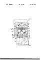
- a support member 98 which may be a tool holder portion of a machine tool of any type, such as a turret or a support member for receiving a single tool.
- the support member 98 has a bore 70 therein for receiving a tool.
- the tool itself comprises an outer head portion formed with a notch or pocket for receiving a cutting insert 86 and having a shank portion receivable in bore 70.
- the shank 100 of the tool is provided with a central axial bore 102 while radial bores 104, which may be three in number, intersect the axial bore.
- Ball elements 106 are mounted in the radial bores and a further ball element 108 is mounted in the axial bore.
- the bore 70 in the support member is counterbored and threaded at the outer end and mounted therein for a steel ring 110 which, at the inner end, has a bevelled end surface 112 for engagement by balls 106.
- Ring 110 preferably has a shoulder which abuts the bottom of the threaded counterbore, as shown, to locate ring 110 axially in the turret or support member.
- the head portion of the tool which is notched to receive a cutting insert 86, has a shoulder to engage the end face of the turret or support member to locate the tool axially in bore 70.
- a screw 114 has an inner end engaging ball 108 and is accessible from the outer end of the tool.
- a lateral slot 116 at the inner end embraces the fixed pin 118 in the bore thereby angularly to locate the tool and, upon rotation of screw 114, ball 108 will move axially inwardly toward pin 118 and will cause balls 106 to move outwardly and engage the inner end of sleeve 110 and thereby draw the tool backwardly toward the support member into a fixed axial location therein.
- a rubber-like O-ring 120 can be provided to retain balls 106 in the respective bores therefor and the rearward end of axial bore 102 may be provided with a rubber-like filler plug 122.
Landscapes
- Engineering & Computer Science (AREA)
- Mechanical Engineering (AREA)
- Gripping On Spindles (AREA)
Abstract
A quick change device for mounting a tool in a support member such as a turret. The tool has a shank with radially outwardly movable balls therein and the mounting device includes a sleeve receivable on the shank and adapted for mounting in a bore in the support member. The shank includes an actuator ball causing the aforementioned balls to move radially outwardly and engage a shoulder at the end of the sleeve to pull the tool into a predetermined axial position and lock the tool in the aforementioned position while cooperating elements of key means in the tool in the support member prevent rotation of the tool in the support member.
Description
The present invention relates to quick change devices for connecting tools to support members, and is a Continuation of copending application Ser. No. 756,790, filed Jan. 4, 1977, and entitled "QUICK CHANGE DEVICE FOR MOUNTING IN SUPPORT MEMBER," now abandoned which was a Division of application Ser. No. 528,159, filed Nov. 29, 1974, and entitled "MACHINE TOOL HAVING A SPECIAL INDEXABLE TURRET AND METHOD OF OPERATION," now U.S. Pat. No. 4,018,112.
In the maintaining of a machine tool in a state of high productivity, it is important to be able to change the cutting tools therein as quickly as possible while, also, precisely locating the cutting tools in the proper position.
In the application parent to the present one, there is shown a turret having a plurality of tools mounted therein, and there is illustrated a number of arrangements for detachably supporting the tools in bores provided therefor in the respective turret.
The present application is concerned with a particular type of quick change device for mounting a tool in a respective bore in a support member such as a turret.
The primary object of the present invention is the provision of a quick change device for connecting tools to support members which is relatively inexpensive to construct, which is accurate in respect of locating the tool and which is extremely quick operating.
According to the present invention, a tool is provided for mounting in a bore in a support member in which the tool has a head at the outer end notched or provided with a pocket for receiving a cutting insert while, on the rearward side of the head, the tool comprises a cylindrical shank, A sleeve or ring fits closely but slidably on the shank and has threads at the head end which are receivable in a counterbored outer end portion of the aforementioned bore in the support member.
The shank has radially movable clamp balls mounted therein and an actuator ball mounted in an axial bore formed in the shank and an actuator screw for moving the actuator ball longitudinally in the bore in the shank. When the actuator ball moves in one direction, the clamp balls carried in the shank will move radially outwardly and will engage the end of the steel ring, and when the actuator ball is moved in the other direction, the clamp balls can be retracted inwardly within the envelope of the shank, and the tool removed from the sleeve, and, therefore, from the support member.
The actuating screw is readily accessible from the outer end of the tool, and the operation of removing a tool from the support member and placing another therein can be carried out quite quickly. The tool has an abutment region at the rearward side of the head that abuts the outer end of the support member when the clamp balls are pushed radially outwardly so that the tool is located radially axially in the bore in the support member. The support member and the tool include cooperating elements of a keying device that nonrotatably connects the tool to the support member when it is mounted therein.
The exact nature of the present invention will become more clearly apparent upon reference to the following detailed specification taken in connection with the accompanying drawing which shows a quick change device according to the present invention.
Referring to the drawing, there is shown therein a support member 98 which may be a tool holder portion of a machine tool of any type, such as a turret or a support member for receiving a single tool. The support member 98 has a bore 70 therein for receiving a tool.
The tool itself comprises an outer head portion formed with a notch or pocket for receiving a cutting insert 86 and having a shank portion receivable in bore 70.
The shank 100 of the tool is provided with a central axial bore 102 while radial bores 104, which may be three in number, intersect the axial bore. Ball elements 106 are mounted in the radial bores and a further ball element 108 is mounted in the axial bore. The bore 70 in the support member is counterbored and threaded at the outer end and mounted therein for a steel ring 110 which, at the inner end, has a bevelled end surface 112 for engagement by balls 106.
A screw 114 has an inner end engaging ball 108 and is accessible from the outer end of the tool. When the shank of the tool is placed in bore 70, a lateral slot 116 at the inner end embraces the fixed pin 118 in the bore thereby angularly to locate the tool and, upon rotation of screw 114, ball 108 will move axially inwardly toward pin 118 and will cause balls 106 to move outwardly and engage the inner end of sleeve 110 and thereby draw the tool backwardly toward the support member into a fixed axial location therein.
A rubber-like O-ring 120 can be provided to retain balls 106 in the respective bores therefor and the rearward end of axial bore 102 may be provided with a rubber-like filler plug 122.
Modifications may be made within the scope of the appended claims.
Claims (8)
1. In combination; a support member and a quick change mounting device for mounting a tool in a work station in said support member and comprising means forming a threaded bore in said support member, a sleeve threaded into said bore and having an inner end presenting a shoulder, means for locating said sleeve in a predetermined axial position in said bore, said tool having a shank having a close sliding fit in said sleeve and receivable in said sleeve from the outer end thereof and protruding inwardly beyond the said shoulder, means for locating said shank in a predetermined axial position in said respective bore, coplanar perforations formed in said shank having axes positioned inwardly from said shoulder when the shank is in said predetermined axial position in said bore, clamp balls in said perforations which engage the shoulder when moved radially outwardly in the respective perforations, a central hole formed in said shank intersecting said perforations, an actuating ball in said hole, means for moving said actuating ball axially in said hole to drive said clamp balls radially outwardly in said perforations into engagement with said shoulder, and means keying said tool against rotation on the axis of said shank in said support member.
2. The combination according to claim 1 in which the bore in the support member is counterbored from the outer end and said sleeve has a second shoulder facing the bottom of said counterbore and engageable therewith when the sleeve is threaded into said bore to locate said sleeve in said prededetermined axial position in the bore.
3. The combination according to claim 1 in which said means for locating said tool axially in the respective bore in the support member comprises cooperating elements of abutment means on the tool and the support member which interengage when the tool shank is inserted into said sleeve from said outer end thereof.
4. The combination according to claim 1 in which said shoulder tapers outwardly toward said inner end of said sleeve.
5. In a support member for receiving a quick detachable tool; at least one planar face formed on said support member and a bore formed in the support member perpendicularly to and through said planar face for receiving a shank on a tool, an axially outer greater diameter portion which is internally threaded to receive a threaded portion on a sleeve closely fitting in said bore and surrounding a tool shank, an axially inner smaller diameter portion and an intermediate diameter portion between said axially outer and axially inner bore portions, said bore including an outwardly facing shoulder located a predetermined distance inwardly from said planar face for engaging a shoulder formed on a sleeve to locate a sleeve axially in said bore, said axially outer bore portion adapted to receive a threaded outer end portion of the sleeve while said intermediate diameter portion adapted closely to embrace the sleeve axially inwardly from the threaded outer end portion of the sleeve, and said axially inner bore portion adapted closely to embrace the shank of the tool mounted in the bore.
6. A sleeve element according to claim 5 which includes a sleeve element in said bore, said sleeve comprising a wear and deformation resistant metal having an externally threaded larger diameter axially outer portion threaded into the axially outer portion of said bore and an axially inner smaller diameter portion fitted in said intermediate diameter portion of said bore and an axially inwardly facing annular shoulder at the juncture of said axially outer and axially inner portions engaging the shoulder in said bore.
7. In combination for use with a support member having a threaded bore; a quick change mounting device for mounting a tool in the bore in the support member and comprising; a sleeve threaded into and having a predetermined axial portion in the said bore and having an inner end presenting a shoulder, said tool having a shank having a close sliding fit in said sleeve and receivable in said sleeve from the outer end thereof and protruding inwardly beyond the said shoulder, said shank having an abutment element engageable with the support member to locate the tool in a predetermined axial position in the bore, coplanar perforations formed in said shank having axes positioned inwardly from said shoulder when the shank is in said predetermined axial position in said bore, clamp balls in said perforations which engage the shoulder when moved radially outwardly in the respective perforations, a central hole formed in said shank intersecting said perforations, an actuating ball in said hole, means for moving said actuating ball axially in said hole to drive said clamp balls radially outwardly in said perforations into engagement with said shoulder, said tool including an element of key means for use in holding the tool against rotation on the axis of said shank in the bore in the support member.
8. The combination according to claim 7 in which the bore in the support member has an axially outwardly facing annular abutment area therein and said sleeve has an axially inwardly facing annular abutment area thereon, said areas being interengageable when the sleeve is threaded into the bore to locate said sleeve in said predetermined axial position in the bore.
Priority Applications (1)
| Application Number | Priority Date | Filing Date | Title |
|---|---|---|---|
| US05/808,968 US4197771A (en) | 1977-01-04 | 1977-06-22 | Quick change device for mounting tool in support member |
Applications Claiming Priority (2)
| Application Number | Priority Date | Filing Date | Title |
|---|---|---|---|
| US75679077A | 1977-01-04 | 1977-01-04 | |
| US05/808,968 US4197771A (en) | 1977-01-04 | 1977-06-22 | Quick change device for mounting tool in support member |
Related Parent Applications (1)
| Application Number | Title | Priority Date | Filing Date |
|---|---|---|---|
| US75679077A Continuation | 1977-01-04 | 1977-01-04 |
Publications (1)
| Publication Number | Publication Date |
|---|---|
| US4197771A true US4197771A (en) | 1980-04-15 |
Family
ID=27116294
Family Applications (1)
| Application Number | Title | Priority Date | Filing Date |
|---|---|---|---|
| US05/808,968 Expired - Lifetime US4197771A (en) | 1977-01-04 | 1977-06-22 | Quick change device for mounting tool in support member |
Country Status (1)
| Country | Link |
|---|---|
| US (1) | US4197771A (en) |
Cited By (20)
| Publication number | Priority date | Publication date | Assignee | Title |
|---|---|---|---|---|
| DE3007440A1 (en) * | 1980-02-28 | 1981-09-17 | Fried. Krupp Gmbh, 4300 Essen | TOOL SETUP WITH INTERCHANGEABLE TOOL HOLDER |
| US4350463A (en) * | 1977-06-13 | 1982-09-21 | Kennametal Inc. | Arrangement for mounting a cutter |
| US4414724A (en) * | 1981-06-24 | 1983-11-15 | The Olofsson Corporation | Tool changing mechanism |
| US4447181A (en) * | 1982-09-07 | 1984-05-08 | Ikegai Tekko Kabushiki Kaisha | Tool holder |
| EP0121665A3 (en) * | 1983-02-10 | 1986-05-14 | SMW Schneider & Weisshaupt GmbH | Apparatus for mounting interchangeable tool blocks |
| US4708040A (en) * | 1987-01-27 | 1987-11-24 | Kennametal Inc. | Lock rod and apparatus for holding a toolholder |
| US4723877A (en) * | 1987-01-27 | 1988-02-09 | Kennametal Inc. | Toolholder |
| US4726268A (en) * | 1987-01-27 | 1988-02-23 | Kennametal Inc. | Clamping apparatus for holding a toolholder shank |
| US4726269A (en) * | 1987-01-27 | 1988-02-23 | Kennametal Inc. | Toolholder assembly |
| US4736659A (en) * | 1987-01-27 | 1988-04-12 | Kennametal Inc. | Apparatus for holding a toolholder shank |
| US4747735A (en) * | 1987-01-27 | 1988-05-31 | Kennametal Inc. | Toolholder and method of releasably mounting |
| US4784542A (en) * | 1985-03-01 | 1988-11-15 | Fried. Krupp Gesellschaft Mit Beschrankter Haftung | Tool-mounting assembly having an exchangeable tool head |
| WO1992011964A1 (en) * | 1991-01-11 | 1992-07-23 | C.M.C. Di Comanduli F.11I S.D.F. | A universal tool for an external turning system |
| US5201621A (en) * | 1990-02-02 | 1993-04-13 | Renishaw Plc | Shank for a tool |
| WO1993007982A1 (en) * | 1991-10-15 | 1993-04-29 | Kennametal Inc. | Ball lock apparatus for small diameter toolholders |
| US6543318B1 (en) | 2001-11-15 | 2003-04-08 | Kennametal Inc. | Locking assembly |
| WO2003066260A1 (en) * | 2002-02-01 | 2003-08-14 | Kennametal Inc. | Tunable toolholder |
| US8734070B2 (en) | 2010-10-20 | 2014-05-27 | Kennametal Inc. | Toolholder with externally-mounted dynamic absorber |
| DE102013104874B3 (en) * | 2013-05-13 | 2014-12-04 | Ott-Jakob Spanntechnik Gmbh | tool turret |
| USD721266S1 (en) | 2012-11-08 | 2015-01-20 | Eric Suyu Sun | Quick connector |
Citations (9)
| Publication number | Priority date | Publication date | Assignee | Title |
|---|---|---|---|---|
| US195769A (en) * | 1877-10-02 | Improvement in tool-posts for lathes | ||
| US3120961A (en) * | 1961-08-08 | 1964-02-11 | Clarkson Engineers Ltd | Chucks |
| US3178969A (en) * | 1962-09-27 | 1965-04-20 | Valeron Corp | Adjustable tool insert |
| US3238600A (en) * | 1964-02-26 | 1966-03-08 | Valeron Corp | Clevis lock cutting tool holder |
| US3498653A (en) * | 1968-08-16 | 1970-03-03 | Kennametal Inc | Connector device |
| US3604293A (en) * | 1967-09-14 | 1971-09-14 | Index Werke Kg Hahn & Tessky | Machine tool |
| US3750498A (en) * | 1969-08-29 | 1973-08-07 | Willen & Cie C | Tool holders for machine tools |
| US3822620A (en) * | 1969-08-29 | 1974-07-09 | Willen & Cie C | Tool holder assembly having means for selectively adjusting the position of the work tool |
| US4024778A (en) * | 1975-10-06 | 1977-05-24 | Fauw James R De | Retractable tool holder |
-
1977
- 1977-06-22 US US05/808,968 patent/US4197771A/en not_active Expired - Lifetime
Patent Citations (9)
| Publication number | Priority date | Publication date | Assignee | Title |
|---|---|---|---|---|
| US195769A (en) * | 1877-10-02 | Improvement in tool-posts for lathes | ||
| US3120961A (en) * | 1961-08-08 | 1964-02-11 | Clarkson Engineers Ltd | Chucks |
| US3178969A (en) * | 1962-09-27 | 1965-04-20 | Valeron Corp | Adjustable tool insert |
| US3238600A (en) * | 1964-02-26 | 1966-03-08 | Valeron Corp | Clevis lock cutting tool holder |
| US3604293A (en) * | 1967-09-14 | 1971-09-14 | Index Werke Kg Hahn & Tessky | Machine tool |
| US3498653A (en) * | 1968-08-16 | 1970-03-03 | Kennametal Inc | Connector device |
| US3750498A (en) * | 1969-08-29 | 1973-08-07 | Willen & Cie C | Tool holders for machine tools |
| US3822620A (en) * | 1969-08-29 | 1974-07-09 | Willen & Cie C | Tool holder assembly having means for selectively adjusting the position of the work tool |
| US4024778A (en) * | 1975-10-06 | 1977-05-24 | Fauw James R De | Retractable tool holder |
Cited By (25)
| Publication number | Priority date | Publication date | Assignee | Title |
|---|---|---|---|---|
| US4350463A (en) * | 1977-06-13 | 1982-09-21 | Kennametal Inc. | Arrangement for mounting a cutter |
| US4406195A (en) * | 1980-02-28 | 1983-09-27 | Fried. Krupp Gesellschaft Mit Beschrankter Haftung | Quick-release tool assembly |
| DE3007440A1 (en) * | 1980-02-28 | 1981-09-17 | Fried. Krupp Gmbh, 4300 Essen | TOOL SETUP WITH INTERCHANGEABLE TOOL HOLDER |
| US4414724A (en) * | 1981-06-24 | 1983-11-15 | The Olofsson Corporation | Tool changing mechanism |
| US4447181A (en) * | 1982-09-07 | 1984-05-08 | Ikegai Tekko Kabushiki Kaisha | Tool holder |
| EP0121665A3 (en) * | 1983-02-10 | 1986-05-14 | SMW Schneider & Weisshaupt GmbH | Apparatus for mounting interchangeable tool blocks |
| US4784542A (en) * | 1985-03-01 | 1988-11-15 | Fried. Krupp Gesellschaft Mit Beschrankter Haftung | Tool-mounting assembly having an exchangeable tool head |
| US4708040A (en) * | 1987-01-27 | 1987-11-24 | Kennametal Inc. | Lock rod and apparatus for holding a toolholder |
| US4726268A (en) * | 1987-01-27 | 1988-02-23 | Kennametal Inc. | Clamping apparatus for holding a toolholder shank |
| US4726269A (en) * | 1987-01-27 | 1988-02-23 | Kennametal Inc. | Toolholder assembly |
| US4736659A (en) * | 1987-01-27 | 1988-04-12 | Kennametal Inc. | Apparatus for holding a toolholder shank |
| US4747735A (en) * | 1987-01-27 | 1988-05-31 | Kennametal Inc. | Toolholder and method of releasably mounting |
| US4723877A (en) * | 1987-01-27 | 1988-02-09 | Kennametal Inc. | Toolholder |
| US4836068A (en) * | 1987-01-27 | 1989-06-06 | Kennametal Inc. | Lock rod and apparatus for holding a toolholder |
| US5201621A (en) * | 1990-02-02 | 1993-04-13 | Renishaw Plc | Shank for a tool |
| WO1992011964A1 (en) * | 1991-01-11 | 1992-07-23 | C.M.C. Di Comanduli F.11I S.D.F. | A universal tool for an external turning system |
| WO1993007982A1 (en) * | 1991-10-15 | 1993-04-29 | Kennametal Inc. | Ball lock apparatus for small diameter toolholders |
| US5209146A (en) * | 1991-10-15 | 1993-05-11 | Kennametal Inc. | Ball lock apparatus for small diameter toolholders |
| AU655848B2 (en) * | 1991-10-15 | 1995-01-12 | Kennametal Inc. | Ball lock apparatus for small diameter toolholders |
| US6543318B1 (en) | 2001-11-15 | 2003-04-08 | Kennametal Inc. | Locking assembly |
| WO2003066260A1 (en) * | 2002-02-01 | 2003-08-14 | Kennametal Inc. | Tunable toolholder |
| US6619165B2 (en) * | 2002-02-01 | 2003-09-16 | Kennametal Inc. | Tunable toolholder |
| US8734070B2 (en) | 2010-10-20 | 2014-05-27 | Kennametal Inc. | Toolholder with externally-mounted dynamic absorber |
| USD721266S1 (en) | 2012-11-08 | 2015-01-20 | Eric Suyu Sun | Quick connector |
| DE102013104874B3 (en) * | 2013-05-13 | 2014-12-04 | Ott-Jakob Spanntechnik Gmbh | tool turret |
Similar Documents
| Publication | Publication Date | Title |
|---|---|---|
| US4197771A (en) | Quick change device for mounting tool in support member | |
| US4135418A (en) | Clamping device | |
| US3851562A (en) | Tool mounting device for a machine tool | |
| SU751313A3 (en) | Fast-changeable chuck | |
| US4228705A (en) | Tool holding device | |
| US4840520A (en) | Mounting device having a conical shank | |
| US3168322A (en) | Chucking device for machine tool spindle and tool holder for use therewith | |
| EP0111368B1 (en) | Device for locating and locking a work holding pallet on a machine tool fixture | |
| JPS643602B2 (en) | ||
| US3219355A (en) | Tool holder | |
| US3822790A (en) | Tool-holding devices | |
| US6932358B1 (en) | Quick change endform tool cartridge | |
| US3678790A (en) | Machine tools | |
| US2833546A (en) | Universal tool holder | |
| US3680436A (en) | Tool changer clamp | |
| US3136217A (en) | Flanged tool adapter | |
| US4402519A (en) | Tool connector | |
| US2231252A (en) | Tool holder | |
| EP0684884B1 (en) | Fastening device for milling tools and the like, adaptable for various holder sizes | |
| US4812091A (en) | Exchange system on an irremovable machining center | |
| US2860883A (en) | Quick change chuck | |
| US3174168A (en) | Self-aligning tool holder | |
| US4679802A (en) | Clamp chuck | |
| US3088351A (en) | Turret tool block | |
| US3288005A (en) | Indexing rotary tool holder |