US4196918A - Utility trailer frame assembly - Google Patents
Utility trailer frame assembly Download PDFInfo
- Publication number
- US4196918A US4196918A US05/906,489 US90648978A US4196918A US 4196918 A US4196918 A US 4196918A US 90648978 A US90648978 A US 90648978A US 4196918 A US4196918 A US 4196918A
- Authority
- US
- United States
- Prior art keywords
- spine
- tongue
- trailer
- wheel
- carried
- Prior art date
- Legal status (The legal status is an assumption and is not a legal conclusion. Google has not performed a legal analysis and makes no representation as to the accuracy of the status listed.)
- Expired - Lifetime
Links
Images


Classifications
-
- B—PERFORMING OPERATIONS; TRANSPORTING
- B62—LAND VEHICLES FOR TRAVELLING OTHERWISE THAN ON RAILS
- B62D—MOTOR VEHICLES; TRAILERS
- B62D21/00—Understructures, i.e. chassis frame on which a vehicle body may be mounted
- B62D21/14—Understructures, i.e. chassis frame on which a vehicle body may be mounted of adjustable length or width
-
- B—PERFORMING OPERATIONS; TRANSPORTING
- B62—LAND VEHICLES FOR TRAVELLING OTHERWISE THAN ON RAILS
- B62D—MOTOR VEHICLES; TRAILERS
- B62D63/00—Motor vehicles or trailers not otherwise provided for
- B62D63/06—Trailers
- B62D63/061—Foldable, extensible or yielding trailers
Definitions
- the present invention is directed to utility trailers, and more particularly to utility trailer frame assemblies which may be disassembled or knocked-down to facilitate storage during periods of non-use.
- a general object of the present invention is to provide a utility trailer, specifically a trailer frame and suspension system, which occupies a minimum of storage space during periods of non-use and which, when in the functional or assembled condition, provides a sturdy, lightweight trailer frame capable of carrying substantial loads.
- a more specific object of the invention is to provide a utility trailer frame assembly of the described type which may be readily assembled and/or disassembled by relatively unskilled members of the consuming public.
- FIG. 1 is an exploded perspective view of a trailer frame assembly in accordance with a presently preferred embodiment of the invention, an exemplary trailer body being illustrated in phantom;
- FIG. 2 is a rear elevational view of a trailer including a trailer frame and suspension system in accordance with the invention
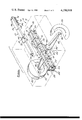
- FIG. 3 is a side sectional of the frame assembly illustrated in FIG. 2 with the draw tongue extended;
- FIGS. 4, 5 and 6 are sectional views taken along the respective lines 4--4, 5--5 and 6--6 in FIG. 3;
- FIG. 7 is a view similar to that of FIG. 3 but illustrating the frame assembly with the draw tongue in the retracted position
- FIG. 8 is a partial sectional view taken along the line 8--8 in FIG. 3;
- FIG. 9 is a rear elevational view of the trailer frame assembly carrying a modified trailer body.
- a trailer frame assembly 10 in accordance with the invention is illustrated as comprising a relatively long and narrow hollow spine 12 adapted to extend lengthwise of a trailer body 14 (FIGS. 1-3) in the direction of travel thereof.
- Spine 12 is an assembly of four lengths 16 of angle iron disposed as longerons to define the spine lateral edgers.
- Upper and lower horizontal U-straps 18 and 18' are disposed externally of the spine enclosure and vertical side straps 20 and 20' are disposed internally in overlapping registration with straps 18, 18', with all the straps being spot welded to angle iron lengths 16 to form a rigid assembly.
- a trailer hitch draw tongue 22 of hollow rectangular channel stock or the like is telescopically carried internally of spine 12 and is slideable longitudinally therewithin between an extended position illustrated in FIG. 3, in which tongue 22 extends from spine 12 and trailer body 14 for coupling to a tow vehicle trailer hitch (not shown), and a retracted storage position illustrated in FIG. 7 in which the tongue is withdrawn into the spine.
- a pair of angle brackets 24,26 bridge the lower spine longerons 16 and cooperate with a section 28 of tube or channel stock welded to the underside of the rear portion 30 of tongue 22 to define respective fore and aft tongue stops at the fully extended (FIG. 3) and fully retracted (FIG. 7) positions of draw tongue 22.
- draw tongue 22 is of similar length to spine 12 so that only a small portion at the hitch end 32 of the draw tongue extends from the spine in the retracted position.
- a pair of vertical plates 34,36 are welded onto opposite interior sides of spine 12 approximately centrally of the spine length in lieu of straps 20,20' for enhanced balance under trailer loads.
- a pair of locating and mounting studs 38,40 are affixed to each plate 34,36 internally of spine 12, the studs being longitudinally aligned and spaced from each other in the direction of the spine longitudinal axis.
- each of the studs 38 (and 40) comprise a substantially cylindrical body portion 42 projecting into corresponding apertures in plates 34,36 and welded thereto, and a frustoconical head portion 44 flaring outwardly from body portion 42 and protruding into the spine enclosure.
- Frame assembly 10 includes a wheel suspension system comprising a pair of tapering monoleaf springs 46,48 adapted at their inboard ends 46',48' to be mounted internally of the trailer spine in a manner to be described.
- Tire carrying wheels 50,52 are rotatably mounted, as by axle spindles 54 (FIG. 2), at the downwardly bent outboard ends 46",48" of springs 46,48 which may also carry fenders of the type illustrated at 56.
- the wheels and wheel-mounting spindles may be of any suitable type and need not be further discussed.
- springs 46,48 include at their inner, upwardly bent wide ends 46' and 48' a pair of longitudinally spaced keyhole apertures 58,60 adapted to be received over respective studs 38,40.
- Apertures 58,60 include rearward enlarged portions 62,64 adapted to be received over stud head portions 44 (FIGS. 4 and 5), and smaller portions 66,68 extending forwardly from the respective enlarged portions longitudinally of the spine and adapted to be received over the stud cylindrical portions 42.
- Compression members or pads 70,72 of plastic such as nylon or other suitable material are affixed to opposite external sides of tongue projection 28 and cooperate with stud mounting plates 34,36 rigidly to clamp therebetween the inboard ends 46',48' of leaf springs 46,48 in the extended position of draw tongue 22 when the leaf springs are received over the mounting studs, as best illustrated in FIGS. 4 and 5.
- Compression pads 70,72 include longitudinally extending channels 74,76 which are adapted to be slideably received over stud head portions 44.
- two pair of forward compression pads 80 and 81 are disposed on the four outside surfaces of tongue 22 and cooperate with corresponding pairs of internally disposed pads 82 and 83, and a lateral bridge member 84 at the mouth of spine 12 firmly to wedge the draw tongue into tight fitting relation with the spine in the extended position of the tongue.
- a pair of rearward pad members 86,86' are disposed one on top of tongue 22 and the other on the bottom of tongue projection 28, and cooperate with corresponding pads 88,88' (FIGS. 3, 5 and 7) disposed internally of spine 12, in combination with the laterally compressive wedging action of spring-retaining pads 70,72, firmly to wedge the rearward end of tongue 22 within the spine in the extended position of the tongue.
- tongue 22 is rigidly wedged in its extended position against movement both sideways and vertically relative to the spine.
- a pair of spring clips 92 (FIG. 1) are riveted internally of tongue 22 slightly forwardly of pads 80 and have inclined yieldable cam fingers projecting laterally outwardly of the tongue through apertures 94 (FIG. 8) adapted to snap into locking abutment against the mouth of spine 12 to releasably lock the tongue in its extended position against longitudinal movement relative to the spine.
- tongue 22 is preassembled at the factory into spine 12, the tongue and spine being shown exploded in FIG. 1 more clearly to illustrate the same.
- leaf springs 46,48 are positioned, by first registering the enlarged apertures 62,64 over the stud heads 44 and then sliding the leaf springs bodily rearwardly of the spine to bring smaller apertures 66,68 into registry with the stud shanks 42. In this position, the respective leaf springs are located and temporarily held in their operative positions by the studs.
- the tongue tip 32 (FIG.
- Tongue 22 is firmly held in its extended position against lateral and rotational movement relative to the spine by the wedging action of the tongue and spine pads, and is locked against relative longitudinal movement by spring clips 92 and forward stop 24.
- a series of notches or indentations 85 is provided along the lower face of channel 28. The tip of a screw driver or crowbar may be inserted into one of the notches 85 and levered against bridge 18 to force the draw tongue outwardly during assembly (or inwardly during disassembly).
- body 14 is such that trailer 10 may be stood on end during storage, assembly or disassembly.
- spring clips 92 are pressed inwardly from their operative positions illustrated in FIG. 8 until clear of pads 83, and the tongue is then pushed into the spring to the retracted position illustrated in FIG. 7.
- wheel suspension springs 46,48 may be demounted by merely sliding the leaf springs forwardly in the spine until apertures 62,64 (FIG. 7) are axially aligned with stud heads 44, and then moving the respective leaf springs inwardly of the spine until clear of the locating studs, whereupon the leaf springs are free to be pulled out from the underside of the spine.
- the box-like trailer body 14, which serves as the load receiving compartment of the trailer preferably is constructed so as to have a longitudinally extending central groove in its underside complementary in cross section to spine 12 and adapted to snugly receive spine 12 therein to help mount and firmly retain body 14 on trailer 12 in balanced cantilever fashion.
- trailer body 96 comprises a pair of bed members 98 centrally and pivotably mounted by a hinge 100 longitudinally carried by spine 12. Eye hooks 102 cooperate with an elastic strap or the like 104 for affixing a load 106 on the trailer body. Similar straps (not shown) may extend from hooks 102 beneath spine 14 to help retain bed members 98 in their folded-down, load-receiving positions.
- the trailer frame assembly in FIG. 9, including wheel suspension springs 46,48, etc., is otherwise identical to that previously described.
- positional or directional adjectives such as "forwardly”, “rearwardly”, “upwardly”, etc. are employed by way of description and not by way of limitation with respect to the orientation of the structure as viewed in the drawing figures. It will be understood that many of the positional and/or directional aspects of the preferred embodiment may be inverted or otherwise reoriented without altering the functional interrelationship of the elements as described and claimed.
Abstract
Description
Claims (22)
Priority Applications (4)
| Application Number | Priority Date | Filing Date | Title |
|---|---|---|---|
| US05/906,489 US4196918A (en) | 1978-05-17 | 1978-05-17 | Utility trailer frame assembly |
| CA319,559A CA1101014A (en) | 1978-05-17 | 1979-01-12 | Utility trailer frame assembly |
| JP1134779A JPS54151220A (en) | 1978-05-17 | 1979-02-02 | Trailer |
| DE19792919341 DE2919341A1 (en) | 1978-05-17 | 1979-05-14 | TRAILERS FOR MOTOR VEHICLES |
Applications Claiming Priority (1)
| Application Number | Priority Date | Filing Date | Title |
|---|---|---|---|
| US05/906,489 US4196918A (en) | 1978-05-17 | 1978-05-17 | Utility trailer frame assembly |
Publications (1)
| Publication Number | Publication Date |
|---|---|
| US4196918A true US4196918A (en) | 1980-04-08 |
Family
ID=25422525
Family Applications (1)
| Application Number | Title | Priority Date | Filing Date |
|---|---|---|---|
| US05/906,489 Expired - Lifetime US4196918A (en) | 1978-05-17 | 1978-05-17 | Utility trailer frame assembly |
Country Status (4)
| Country | Link |
|---|---|
| US (1) | US4196918A (en) |
| JP (1) | JPS54151220A (en) |
| CA (1) | CA1101014A (en) |
| DE (1) | DE2919341A1 (en) |
Cited By (21)
| Publication number | Priority date | Publication date | Assignee | Title |
|---|---|---|---|---|
| FR2536360A1 (en) * | 1982-11-18 | 1984-05-25 | Bollini Pierre | Multipurpose transformable vehicle, especially for transporting horses. |
| US4811967A (en) * | 1986-01-17 | 1989-03-14 | Hensley James C | Trailer hitch |
| US5249821A (en) * | 1991-01-26 | 1993-10-05 | John Raymond Evans | Trailer capable of being dismantled to readily storable condition |
| US5660409A (en) * | 1996-05-29 | 1997-08-26 | Hensley; James C. | Antisway trailer hitch with surge break accommodations |
| US6199909B1 (en) | 1996-09-23 | 2001-03-13 | Reese Products, Inc. | Trailer |
| US6481734B1 (en) * | 1997-02-11 | 2002-11-19 | Blake Design Group, Llc. | Trailer hitch cover assembly |
| WO2003033285A3 (en) * | 2001-10-12 | 2003-11-20 | Blake Design Group Llc | Trailer hitch cover assembly |
| US6773025B1 (en) * | 2002-11-27 | 2004-08-10 | Jamie B. Zelm | Collapsible trailer |
| US6851696B1 (en) | 2003-02-14 | 2005-02-08 | James C. Hensley Revocable Living Trust A | Trailer hitch with separated functions |
| US6874806B1 (en) | 2002-07-29 | 2005-04-05 | Blake Design Group, Llc. | Trailer hitch cover assembly |
| US6880880B1 (en) * | 2002-03-15 | 2005-04-19 | Lonnie D. Armstrong | Take-off trailer |
| US6971663B1 (en) | 1997-02-11 | 2005-12-06 | Blake Design Group, Llc. | Trailer hitch cover assembly |
| US20060138745A1 (en) * | 2004-02-13 | 2006-06-29 | Hensley James C | Trailer hitch with separated functions |
| US20070170701A1 (en) * | 2006-01-26 | 2007-07-26 | Serge Dugal | Trailer having removably attachable wheel assemblies |
| US20090033061A1 (en) * | 2007-08-01 | 2009-02-05 | James C. Hensley Revocable Living Trust A | Trailer hitch with adjustable hitch bar |
| US20100255631A1 (en) * | 2008-09-09 | 2010-10-07 | Sanyo Electric Co., Ltd. | Method for manufacturing solar cell module |
| US20110155484A1 (en) * | 2009-12-29 | 2011-06-30 | Xiaolong Gong | Vehicle |
| US20130193670A1 (en) * | 2012-01-25 | 2013-08-01 | John R. Columbia | Multi-Function Hitch Accessory Retaining Device And Method |
| US20160257361A1 (en) * | 2013-10-18 | 2016-09-08 | J.G.B.D. Consult Sprl | Heavy-load modular vehicle |
| CN110026965A (en) * | 2019-04-30 | 2019-07-19 | 洛阳理工学院 | A kind of device that control equipment automatically moves |
| US11097578B2 (en) | 2018-01-24 | 2021-08-24 | Lippert Components, Inc. | Trailer frame with curved drawbars |
Families Citing this family (4)
| Publication number | Priority date | Publication date | Assignee | Title |
|---|---|---|---|---|
| US5161814A (en) * | 1989-04-28 | 1992-11-10 | Walker Douglas W | Trailerable structure with retractable suspension |
| DE19543600A1 (en) * | 1995-11-23 | 1997-05-28 | Muenz Fahrzeugbau | Trailer for motor vehicle, especially for passenger car |
| DE102004036411B4 (en) * | 2004-07-27 | 2008-06-12 | Goldhofer Ag | Vehicle for transporting heavy loads |
| DE102013107453B3 (en) * | 2013-07-15 | 2014-08-28 | Wanzl Metallwarenfabrik Gmbh | Movable transport carriage, has drawbar provided with guide rail, which is arranged at undersideds of wagons, and drawbar and carriage articulately interconnected, where guide rail is formed with two longitudinal slots |
Citations (23)
| Publication number | Priority date | Publication date | Assignee | Title |
|---|---|---|---|---|
| US1835436A (en) * | 1928-01-16 | 1931-12-08 | Shaw Edward Wharton | Trailer |
| US2080709A (en) * | 1935-08-16 | 1937-05-18 | Dwight F Hall | Trailer for automobiles |
| US2163653A (en) * | 1937-02-26 | 1939-06-27 | Sylvester J Wittman | Airplane landing gear |
| US2353999A (en) * | 1943-08-24 | 1944-07-18 | Counts Kermit Astor | Wooden wagon and spring therefor |
| US2469506A (en) * | 1946-02-23 | 1949-05-10 | Kerr Kingdon | Folding wheel trailer |
| US2490184A (en) * | 1948-06-08 | 1949-12-06 | Jr Joseph Wojtech | Wheel support |
| US2534722A (en) * | 1947-01-10 | 1950-12-19 | Jr Thomas W Meiklejohn | Wheel suspension |
| US2819768A (en) * | 1953-06-10 | 1958-01-14 | Daimler Benz Ag | Wheel suspension in motor vehicles by means of leaf springs |
| US2826425A (en) * | 1955-07-26 | 1958-03-11 | George F Hoeper | Collapsible trailer |
| US2876036A (en) * | 1954-11-05 | 1959-03-03 | Julius L Olson | Collapsible trailer |
| US2896969A (en) * | 1958-01-10 | 1959-07-28 | Carty John | Retractable hitch structure for house trailers or the like |
| US2916302A (en) * | 1957-07-22 | 1959-12-08 | Warren R Lippitt | Removable trailer hitch |
| US3002742A (en) * | 1960-04-20 | 1961-10-03 | Troy Leonard | Vehicle suspension system |
| US3081125A (en) * | 1959-12-07 | 1963-03-12 | Petersen Willy | Folding trailers |
| US3279819A (en) * | 1964-10-30 | 1966-10-18 | William D Edmonds | Independently movable trailer tongue section |
| US3378280A (en) * | 1965-10-21 | 1968-04-16 | Jack E. Harms | Hitch assembly |
| US3442268A (en) * | 1966-01-13 | 1969-05-06 | Johnson & Johnson | Breast pad |
| US3572764A (en) * | 1968-12-16 | 1971-03-30 | Richard J Rubin | Retractable hitching device |
| US3612600A (en) * | 1970-05-28 | 1971-10-12 | Luis G Salichs | Folding utility trailer |
| US3781030A (en) * | 1972-08-30 | 1973-12-25 | P Ekedal | Power drawn collapsible trailer |
| US3784230A (en) * | 1971-12-27 | 1974-01-08 | A Worrall | Utility trailer |
| US3917316A (en) * | 1974-10-03 | 1975-11-04 | Raymond Lee Organization Inc | Trunk storing utility trailer for auto |
| US3979133A (en) * | 1975-09-08 | 1976-09-07 | Spec-Co Industries, Inc. | Foldable trailer |
-
1978
- 1978-05-17 US US05/906,489 patent/US4196918A/en not_active Expired - Lifetime
-
1979
- 1979-01-12 CA CA319,559A patent/CA1101014A/en not_active Expired
- 1979-02-02 JP JP1134779A patent/JPS54151220A/en active Pending
- 1979-05-14 DE DE19792919341 patent/DE2919341A1/en not_active Withdrawn
Patent Citations (23)
| Publication number | Priority date | Publication date | Assignee | Title |
|---|---|---|---|---|
| US1835436A (en) * | 1928-01-16 | 1931-12-08 | Shaw Edward Wharton | Trailer |
| US2080709A (en) * | 1935-08-16 | 1937-05-18 | Dwight F Hall | Trailer for automobiles |
| US2163653A (en) * | 1937-02-26 | 1939-06-27 | Sylvester J Wittman | Airplane landing gear |
| US2353999A (en) * | 1943-08-24 | 1944-07-18 | Counts Kermit Astor | Wooden wagon and spring therefor |
| US2469506A (en) * | 1946-02-23 | 1949-05-10 | Kerr Kingdon | Folding wheel trailer |
| US2534722A (en) * | 1947-01-10 | 1950-12-19 | Jr Thomas W Meiklejohn | Wheel suspension |
| US2490184A (en) * | 1948-06-08 | 1949-12-06 | Jr Joseph Wojtech | Wheel support |
| US2819768A (en) * | 1953-06-10 | 1958-01-14 | Daimler Benz Ag | Wheel suspension in motor vehicles by means of leaf springs |
| US2876036A (en) * | 1954-11-05 | 1959-03-03 | Julius L Olson | Collapsible trailer |
| US2826425A (en) * | 1955-07-26 | 1958-03-11 | George F Hoeper | Collapsible trailer |
| US2916302A (en) * | 1957-07-22 | 1959-12-08 | Warren R Lippitt | Removable trailer hitch |
| US2896969A (en) * | 1958-01-10 | 1959-07-28 | Carty John | Retractable hitch structure for house trailers or the like |
| US3081125A (en) * | 1959-12-07 | 1963-03-12 | Petersen Willy | Folding trailers |
| US3002742A (en) * | 1960-04-20 | 1961-10-03 | Troy Leonard | Vehicle suspension system |
| US3279819A (en) * | 1964-10-30 | 1966-10-18 | William D Edmonds | Independently movable trailer tongue section |
| US3378280A (en) * | 1965-10-21 | 1968-04-16 | Jack E. Harms | Hitch assembly |
| US3442268A (en) * | 1966-01-13 | 1969-05-06 | Johnson & Johnson | Breast pad |
| US3572764A (en) * | 1968-12-16 | 1971-03-30 | Richard J Rubin | Retractable hitching device |
| US3612600A (en) * | 1970-05-28 | 1971-10-12 | Luis G Salichs | Folding utility trailer |
| US3784230A (en) * | 1971-12-27 | 1974-01-08 | A Worrall | Utility trailer |
| US3781030A (en) * | 1972-08-30 | 1973-12-25 | P Ekedal | Power drawn collapsible trailer |
| US3917316A (en) * | 1974-10-03 | 1975-11-04 | Raymond Lee Organization Inc | Trunk storing utility trailer for auto |
| US3979133A (en) * | 1975-09-08 | 1976-09-07 | Spec-Co Industries, Inc. | Foldable trailer |
Cited By (31)
| Publication number | Priority date | Publication date | Assignee | Title |
|---|---|---|---|---|
| FR2536360A1 (en) * | 1982-11-18 | 1984-05-25 | Bollini Pierre | Multipurpose transformable vehicle, especially for transporting horses. |
| US4811967A (en) * | 1986-01-17 | 1989-03-14 | Hensley James C | Trailer hitch |
| US5249821A (en) * | 1991-01-26 | 1993-10-05 | John Raymond Evans | Trailer capable of being dismantled to readily storable condition |
| US5660409A (en) * | 1996-05-29 | 1997-08-26 | Hensley; James C. | Antisway trailer hitch with surge break accommodations |
| US6199909B1 (en) | 1996-09-23 | 2001-03-13 | Reese Products, Inc. | Trailer |
| US6945551B2 (en) * | 1997-02-11 | 2005-09-20 | Blake Design Group, Llc. | Trailer hitch cover assembly |
| US6481734B1 (en) * | 1997-02-11 | 2002-11-19 | Blake Design Group, Llc. | Trailer hitch cover assembly |
| US6719318B1 (en) | 1997-02-11 | 2004-04-13 | Blake Design Group, Llc | Trailer hitch cover assembly |
| US6971663B1 (en) | 1997-02-11 | 2005-12-06 | Blake Design Group, Llc. | Trailer hitch cover assembly |
| WO2003033285A3 (en) * | 2001-10-12 | 2003-11-20 | Blake Design Group Llc | Trailer hitch cover assembly |
| US6880880B1 (en) * | 2002-03-15 | 2005-04-19 | Lonnie D. Armstrong | Take-off trailer |
| US6874806B1 (en) | 2002-07-29 | 2005-04-05 | Blake Design Group, Llc. | Trailer hitch cover assembly |
| US6773025B1 (en) * | 2002-11-27 | 2004-08-10 | Jamie B. Zelm | Collapsible trailer |
| US6851696B1 (en) | 2003-02-14 | 2005-02-08 | James C. Hensley Revocable Living Trust A | Trailer hitch with separated functions |
| US20060138745A1 (en) * | 2004-02-13 | 2006-06-29 | Hensley James C | Trailer hitch with separated functions |
| US7364180B2 (en) | 2004-02-13 | 2008-04-29 | James C. Hensley Revocable Living Trust A | Trailer hitch with separated functions |
| US20070170701A1 (en) * | 2006-01-26 | 2007-07-26 | Serge Dugal | Trailer having removably attachable wheel assemblies |
| US20090033061A1 (en) * | 2007-08-01 | 2009-02-05 | James C. Hensley Revocable Living Trust A | Trailer hitch with adjustable hitch bar |
| US7857344B2 (en) | 2007-08-01 | 2010-12-28 | James C. Hensley | Trailer hitch with adjustable hitch bar |
| US20110037242A1 (en) * | 2007-08-01 | 2011-02-17 | James C. Hensley Revocable Living Trust A | Trailer hitch with adjustable hitch bar |
| US8226106B2 (en) | 2007-08-01 | 2012-07-24 | James C. Hensley Revocable Living Trust A | Trailer hitch with adjustable hitch bar |
| US20100255631A1 (en) * | 2008-09-09 | 2010-10-07 | Sanyo Electric Co., Ltd. | Method for manufacturing solar cell module |
| US8505657B2 (en) * | 2009-12-29 | 2013-08-13 | Xiaolong Gong | Vehicle suspension and drive system |
| US20110155484A1 (en) * | 2009-12-29 | 2011-06-30 | Xiaolong Gong | Vehicle |
| US20130193670A1 (en) * | 2012-01-25 | 2013-08-01 | John R. Columbia | Multi-Function Hitch Accessory Retaining Device And Method |
| US9242521B2 (en) * | 2012-01-25 | 2016-01-26 | John R. Columbia | Multi-function hitch accessory retaining device and method |
| US10166827B2 (en) | 2012-01-25 | 2019-01-01 | John R. Columbia | Multi-function hitch accessory retaining device and method |
| US20160257361A1 (en) * | 2013-10-18 | 2016-09-08 | J.G.B.D. Consult Sprl | Heavy-load modular vehicle |
| US9988113B2 (en) * | 2013-10-18 | 2018-06-05 | J.G.B.D. Consult Sprl | Heavy-load modular vehicle |
| US11097578B2 (en) | 2018-01-24 | 2021-08-24 | Lippert Components, Inc. | Trailer frame with curved drawbars |
| CN110026965A (en) * | 2019-04-30 | 2019-07-19 | 洛阳理工学院 | A kind of device that control equipment automatically moves |
Also Published As
| Publication number | Publication date |
|---|---|
| JPS54151220A (en) | 1979-11-28 |
| CA1101014A (en) | 1981-05-12 |
| DE2919341A1 (en) | 1979-11-22 |
Similar Documents
| Publication | Publication Date | Title |
|---|---|---|
| US4196918A (en) | Utility trailer frame assembly | |
| US4564212A (en) | Baby stroller and frame structure therefor | |
| US4280713A (en) | Trailer hitch | |
| US4078821A (en) | Utility trailer | |
| US4202562A (en) | Trailer hitch | |
| US6099035A (en) | Wheeled or vehicle-mounted cart apparatus | |
| US3912139A (en) | Removable vehicle mounted cycle carrier | |
| US5387001A (en) | Combination vehicle towing dolly and flatbed trailer | |
| US8979112B2 (en) | Adjustable hitch assembly | |
| US5135145A (en) | Mountain bike rack | |
| US5577746A (en) | Folding transport vehicle | |
| US4426097A (en) | Hitch adapter for single-wheel trainer | |
| US5397148A (en) | Convertible trailer assembly | |
| US3887208A (en) | Collapsible and portable utility cart | |
| US4892166A (en) | Motorized wheelchair assembly having coupling device | |
| US7246733B2 (en) | Apparatus for carrying cargo | |
| US20100127479A1 (en) | Adjustable hitch assembly | |
| US3567249A (en) | One-wheeled cycle trailer and hitch therefor | |
| US9714060B2 (en) | Modular trailer apparatus | |
| US4119331A (en) | Collapsible golf cart trailer | |
| EP3663172A1 (en) | Utility vehicle with collapsible rear cab frame | |
| US4883283A (en) | Improved hitch and suspension for one-wheel cycle trailers | |
| US4729574A (en) | Wheeled material carrier | |
| US5016897A (en) | Multi-function towing trailer | |
| US3428336A (en) | Boat trailer tongue extension apparatus |
Legal Events
| Date | Code | Title | Description |
|---|---|---|---|
| AS | Assignment |
Owner name: CONGRESS FINANCIAL CORPORATION (CENTRAL), ILLINOIS Free format text: AMENDED AND RESTATED PATENT LICENSE AND COLLATERAL ASSIGNMENT.;ASSIGNOR:MOTOR WHEEL CORPORATION;REEL/FRAME:006484/0108 Effective date: 19930301 |
|
| AS | Assignment |
Owner name: MOTOR WHEEL CORPORATION, MICHIGAN Free format text: RELEASE AND TERMINATION;ASSIGNOR:CONGRESS FINANCIAL CORPORATION (CENTRAL);REEL/FRAME:008098/0501 Effective date: 19960702 |
|
| AS | Assignment |
Owner name: CANADIAN IMPERIAL BANK OF COMMERCE (AS AGENT), NEW Free format text: SECURITY AGREEMENT;ASSIGNORS:HAYES WHEELS INTERNATIONAL, INC;MOTOR WHEEL CORPORATION;MWC ACQUISTIONSUB, INC, (D/B/A TRU-RURN CORPORATION.;REEL/FRAME:008104/0067 Effective date: 19960627 |