US4187926A - Loudspeaker horn - Google Patents
Loudspeaker horn Download PDFInfo
- Publication number
- US4187926A US4187926A US05/967,739 US96773978A US4187926A US 4187926 A US4187926 A US 4187926A US 96773978 A US96773978 A US 96773978A US 4187926 A US4187926 A US 4187926A
- Authority
- US
- United States
- Prior art keywords
- walls
- section
- pair
- throat section
- bell
- Prior art date
- Legal status (The legal status is an assumption and is not a legal conclusion. Google has not performed a legal analysis and makes no representation as to the accuracy of the status listed.)
- Expired - Lifetime
Links
- 238000000926 separation method Methods 0.000 claims description 2
- 239000006185 dispersion Substances 0.000 abstract description 12
- 230000005855 radiation Effects 0.000 description 3
- 230000005574 cross-species transmission Effects 0.000 description 1
- 238000010586 diagram Methods 0.000 description 1
- 230000000694 effects Effects 0.000 description 1
Images


Classifications
-
- G—PHYSICS
- G10—MUSICAL INSTRUMENTS; ACOUSTICS
- G10K—SOUND-PRODUCING DEVICES; METHODS OR DEVICES FOR PROTECTING AGAINST, OR FOR DAMPING, NOISE OR OTHER ACOUSTIC WAVES IN GENERAL; ACOUSTICS NOT OTHERWISE PROVIDED FOR
- G10K11/00—Methods or devices for transmitting, conducting or directing sound in general; Methods or devices for protecting against, or for damping, noise or other acoustic waves in general
- G10K11/02—Mechanical acoustic impedances; Impedance matching, e.g. by horns; Acoustic resonators
- G10K11/025—Mechanical acoustic impedances; Impedance matching, e.g. by horns; Acoustic resonators horns for impedance matching
Definitions
- This invention relates to loudspeaker horns, and more particularly to such a horn utilizing outwardly flaring walls forming a bell section which runs between a rectangular cross-sectioned throat section and a rectangular mouth.
- horn type loudspeakers which are generally employed to provide acoustical output in the frequency range of 400-16,000 hertz, it is difficult to maintain control of the acoustical output to a desired dispersion pattern throughout the frequency range of interest. Control is particularly difficult in the low frequency portion of this range where in even the best prior art horn loudspeakers, control of the vertical desired coverage angle and the dispersion pattern of the acoustical energy departs considerably from the optimum desired pattern. Many of the prior art loudspeakers employ exponentially curved walls. Others, such as that described in U.S. Pat. No. 2,537,141, employ an arcuate mouth and multiple cell elements. Neither of these types of prior art horns is capable of achieving the low frequency control of the present invention.
- a horn which has a first section having a pair of side walls which curve outwardly and which has a cross-sectional area which increases as an exponential function of the distance from the throat, a second section having a cross-sectional area which increases as the square of the distance from the interface with the first section and this expands conically, and a third section which has top and bottom planar walls and curved side walls and a crosssectional area which increases as the square of the distance from its interface with the second section and thus also expands conically.
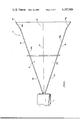
- FIG. 1 is a front elevational view of a preferred embodiment of the invention
- FIG. 2 is a cross-sectional view taken along the plane indicated by 2--2 in FIG. 1;
- FIG. 3 is a cross-sectional view taken along the plane indicated by 3--3 in FIG. 1;
- FIG. 4 and FIG. 5 are polar diagrams comparing sound radiation patterns of the device of the present invention with that of a prior art loudspeaker horn.
- the throat section of a loudspeaker horn is rectangular in cross section with acoustical energy being coupled thereto from a driver unit.
- the throat section has an expanding cross-sectional area and side walls which are substantially parallel, the side walls being joined together by top and bottom walls which diverge outwardly from each other.
- the mouth of the horn has a rectangular configuration, which in the illustrative embodiment is square, and is formed by a bell section having walls which diverge outwardly from the throat section, there being a first pair of diverging top and bottom walls, and a second pair of diverging side walls which join with the top and bottom walls along the edges thereof to form an integral unit.
- the walls of the bell section may be flared outwardly an additional amount at a portion thereof immediately adjacent to the mouth to provide improved control in the midfrequency range of the speaker.
- the divergenceangle between the top and bottom walls and that between the side walls generally determines the dispersion angle of the acoustical energy.
- the divergence angle between the side walls of the bell section is substantially greater than that between the top and bottom walls of this section and these top and bottom walls form continuums of the top and bottom walls of the throat section.
- a significant feature of the present invention is that the horizontal and vertical angles and the dimensions across the mouth (which determine the directivity control bandwidths) can be varied independently and in so doing the characteristic throat section of the horn can be generated.
- Throat section 15 has a pair of opposite walls 15a and 15b which are substantially parallel to each other through most of their lengths, and which are joined together by diverging top and bottom planar walls 15c and 15d.
- the mouth 20 of the horn is rectangular (square in the illustratative embodiment) in shape and is formed by a bell section 19 having a pair of diverging planar side walls 21 and 22 which flare outwardly from throat section 15, and a pair of diverging planar top and bottom walls 24 and 25 which also flare outwardly from throat section 15 and are joined along their edges to the edges of walls 21 and 22.
- Walls 24 and 25 have first portions 24a and 25a which diverge outwardly at a first lesser angle, and second portions 24b and 25b which diverge outwardly at a second greater angle.
- Wall portions 24a and 25a are coplanar with walls 15c and 15d respectively, and thus are continuums thereof.
- the angle of divergence of wall portions 24b and 25b is generally made greater than that of wall portions 24a and 25a by a factor which is directly proportional to the desired angle of coverage of the speaker. It has been found that the additional divergence between wall portions 24b and 25b provides better control of the desired angle on this axis in the midrange of the frequencies of interest (1-5 kHz). If so desired, similar additionally diverging wall portions can be provided at the mouth ends of wall portions 21 and 22.
- the separation between walls 15a and 15b of the throat section at their juncture with bell section walls 21 and 22 should be no greater than the wavelength of sound at the highest frequency to be controlled. It is also important to note the divergence angle between walls 21 and 22 is substantially greater than that between walls 15c and 15d, and that the vertical mouth dimension may be made greater than in a normal horn designed for the same coverage angle. This enables better vertical directivity control at low frequencies of interest in a speaker of normal physical proportions.
- FIGS. 4 and 5 polar graphs showing the sound radiation patterns of the speaker of the present invention as compared with a typical prior art speaker (that described in U.S. Pat. No. 4,071,112) are shown.
- graph line 32 shows the dispersion pattern of the acoustical energy at 800 Hz from a loudspeaker horn designed in accordance with the present invention.
- the optimum dispersion pattern designed for in this instance was one generally pie-shaped and having an angle of 45° (i.e., with the quarter power points separated from each other by 45° ).
- the quarter power points 33 and 34 are separated from each other by 43°.
- Graph line 37 shows the acoustical dispersion pattern at 800 Hz of a prior art horn having the best directivity control characteristics heretofore known.
- the design attempt was for a 40° dispersion.
- the acoustical output of this prior art horn has its quarter power points 38 and 39 separated by 84° and has a dispersion pattern which is a considerably greater departure from the optimum than that of the present invention.
- FIG. 5 the acoustical dispersion patterns of the speaker of the present invention and that of the same prior art speaker as for FIG. 4 are illustrated for 2500 Hz (the midrange of the speaker outputs).
- Graph line 40 shows the pattern for the speaker of the present invention
- graph line 41 shows that of the prior art speaker.
- the quarter power points 43 and 44 of the instant speaker are 40° apart as compared with 58° for the quarter power points 47 and 48 of the prior art speaker.
- There is also a considerable difference between the two directivity patterns indicating a substantial improvement in directivity control in the midfrequency range for the speaker of the present invention, more acoustic power being delivered at the desired coverage angle.
- the device of the present invention thus provides a substantial improvement over the prior art in its directivity control characteristics in the low and mid-frequency ranges of the horn.
Landscapes
- Physics & Mathematics (AREA)
- Engineering & Computer Science (AREA)
- Acoustics & Sound (AREA)
- Multimedia (AREA)
- Obtaining Desirable Characteristics In Audible-Bandwidth Transducers (AREA)
Abstract
Description
Claims (6)
Priority Applications (1)
| Application Number | Priority Date | Filing Date | Title |
|---|---|---|---|
| US05/967,739 US4187926A (en) | 1977-06-27 | 1978-12-08 | Loudspeaker horn |
Applications Claiming Priority (2)
| Application Number | Priority Date | Filing Date | Title |
|---|---|---|---|
| US81064277A | 1977-06-27 | 1977-06-27 | |
| US05/967,739 US4187926A (en) | 1977-06-27 | 1978-12-08 | Loudspeaker horn |
Related Parent Applications (1)
| Application Number | Title | Priority Date | Filing Date |
|---|---|---|---|
| US81064277A Continuation-In-Part | 1977-06-27 | 1977-06-27 |
Publications (1)
| Publication Number | Publication Date |
|---|---|
| US4187926A true US4187926A (en) | 1980-02-12 |
Family
ID=27123376
Family Applications (1)
| Application Number | Title | Priority Date | Filing Date |
|---|---|---|---|
| US05/967,739 Expired - Lifetime US4187926A (en) | 1977-06-27 | 1978-12-08 | Loudspeaker horn |
Country Status (1)
| Country | Link |
|---|---|
| US (1) | US4187926A (en) |
Cited By (28)
| Publication number | Priority date | Publication date | Assignee | Title |
|---|---|---|---|---|
| FR2482402A1 (en) * | 1980-05-06 | 1981-11-13 | Lansing Sound | SPEAKER PAVILION |
| US4344504A (en) * | 1981-03-27 | 1982-08-17 | Community Light & Sound, Inc. | Directional loudspeaker |
| US4390078A (en) * | 1982-02-23 | 1983-06-28 | Community Light & Sound, Inc. | Loudspeaker horn |
| FR2553249A1 (en) * | 1983-10-05 | 1985-04-12 | Jbl Inc | SPEAKER PAVILION COVERING A BOUNDARY AREA |
| US4635749A (en) * | 1981-08-31 | 1987-01-13 | Alan M Tattersall | Speaker enclosure |
| US4963855A (en) * | 1990-02-21 | 1990-10-16 | Kobishi Electric Co., Inc. Ltd. | Warning sound generating device |
| US5020630A (en) * | 1989-12-08 | 1991-06-04 | Electro-Voice, Inc. | Loudspeaker and horn therefor |
| US5285025A (en) * | 1989-04-27 | 1994-02-08 | Toa Corporation | Loudspeaker horn |
| US5925856A (en) * | 1996-06-17 | 1999-07-20 | Meyer Sound Laboratories Incorporated | Loudspeaker horn |
| US6059069A (en) * | 1999-03-05 | 2000-05-09 | Peavey Electronics Corporation | Loudspeaker waveguide design |
| US6094495A (en) * | 1998-09-24 | 2000-07-25 | Eastern Acoustic Works, Inc. | Horn-type loudspeaker system |
| US6112847A (en) * | 1999-03-15 | 2000-09-05 | Clair Brothers Audio Enterprises, Inc. | Loudspeaker with differentiated energy distribution in vertical and horizontal planes |
| US6118883A (en) * | 1998-09-24 | 2000-09-12 | Eastern Acoustic Works, Inc. | System for controlling low frequency acoustical directivity patterns and minimizing directivity discontinuities during frequency transitions |
| US6394223B1 (en) | 1999-03-12 | 2002-05-28 | Clair Brothers Audio Enterprises, Inc. | Loudspeaker with differential energy distribution in vertical and horizontal planes |
| US6712177B2 (en) | 2000-05-30 | 2004-03-30 | Mark S. Ureda | Cross-fired multiple horn loudspeaker system |
| US20040060768A1 (en) * | 2002-09-17 | 2004-04-01 | Murphy David John | Constant directivity acoustic horn |
| US20040240697A1 (en) * | 2003-05-27 | 2004-12-02 | Keele D. Broadus | Constant-beamwidth loudspeaker array |
| US20060153407A1 (en) * | 2003-05-27 | 2006-07-13 | KEELE D B Jr | Reflective loudspeaker array |
| US20080059132A1 (en) * | 2006-09-04 | 2008-03-06 | Krix Loudspeakers Pty Ltd | Method of designing a sound waveguide surface |
| US20090057052A1 (en) * | 2007-08-30 | 2009-03-05 | Klipsch, Llc | Acoustic horn having internally raised geometric shapes |
| US7590257B1 (en) | 2004-12-22 | 2009-09-15 | Klipsch, Llc | Axially propagating horn array for a loudspeaker |
| US7936892B2 (en) | 2002-01-14 | 2011-05-03 | Harman International Industries, Incorporated | Constant coverage waveguide |
| WO2012018735A1 (en) | 2010-08-04 | 2012-02-09 | Robert Bosch Gmbh | Annular ring acoustic transformer |
| WO2012018747A2 (en) | 2010-08-04 | 2012-02-09 | Robert Bosch Gmbh | Equal expansion rate symmetric acoustic transformer |
| US9571923B2 (en) | 2015-01-19 | 2017-02-14 | Harman International Industries, Incorporated | Acoustic waveguide |
| USD797083S1 (en) * | 2013-07-10 | 2017-09-12 | Stanley G. Coates | Sound deflecting apparatus |
| USD814441S1 (en) * | 2016-05-16 | 2018-04-03 | Scott Hanna | Loudspeaker horn |
| USD819606S1 (en) * | 2015-11-26 | 2018-06-05 | Ricoh Company, Ltd. | Speaker with multiple diaphragms |
Citations (6)
| Publication number | Priority date | Publication date | Assignee | Title |
|---|---|---|---|---|
| US1365249A (en) * | 1921-01-11 | Phonograph-horn | ||
| US1526819A (en) * | 1922-08-04 | 1925-02-17 | Amoroso Giuseppe | Horn |
| US2071153A (en) * | 1935-05-07 | 1937-02-16 | Alexander I Abrahams | Acoustic horn |
| US2537141A (en) * | 1945-06-15 | 1951-01-09 | Paul W Klipsch | Loud-speaker horn |
| US2690231A (en) * | 1950-03-09 | 1954-09-28 | Univ Loudspeakers Inc | Acoustic device |
| US4071112A (en) * | 1975-09-30 | 1978-01-31 | Electro-Voice, Incorporated | Horn loudspeaker |
-
1978
- 1978-12-08 US US05/967,739 patent/US4187926A/en not_active Expired - Lifetime
Patent Citations (6)
| Publication number | Priority date | Publication date | Assignee | Title |
|---|---|---|---|---|
| US1365249A (en) * | 1921-01-11 | Phonograph-horn | ||
| US1526819A (en) * | 1922-08-04 | 1925-02-17 | Amoroso Giuseppe | Horn |
| US2071153A (en) * | 1935-05-07 | 1937-02-16 | Alexander I Abrahams | Acoustic horn |
| US2537141A (en) * | 1945-06-15 | 1951-01-09 | Paul W Klipsch | Loud-speaker horn |
| US2690231A (en) * | 1950-03-09 | 1954-09-28 | Univ Loudspeakers Inc | Acoustic device |
| US4071112A (en) * | 1975-09-30 | 1978-01-31 | Electro-Voice, Incorporated | Horn loudspeaker |
Cited By (44)
| Publication number | Priority date | Publication date | Assignee | Title |
|---|---|---|---|---|
| FR2482402A1 (en) * | 1980-05-06 | 1981-11-13 | Lansing Sound | SPEAKER PAVILION |
| US4308932A (en) * | 1980-05-06 | 1982-01-05 | James B. Lansing Sound, Inc. ("Jbl") | Loudspeaker horn |
| DE3116307A1 (en) * | 1980-05-06 | 1982-03-18 | James B. Lansing Sound, Inc., Northridge, Calif. | "SPEAKER FUNNEL" |
| US4344504A (en) * | 1981-03-27 | 1982-08-17 | Community Light & Sound, Inc. | Directional loudspeaker |
| US4635749A (en) * | 1981-08-31 | 1987-01-13 | Alan M Tattersall | Speaker enclosure |
| US4390078A (en) * | 1982-02-23 | 1983-06-28 | Community Light & Sound, Inc. | Loudspeaker horn |
| FR2553249A1 (en) * | 1983-10-05 | 1985-04-12 | Jbl Inc | SPEAKER PAVILION COVERING A BOUNDARY AREA |
| EP0140465A3 (en) * | 1983-10-05 | 1986-03-19 | Jbl Incorporated | Defined-coverage loudspeaker horn |
| US5285025A (en) * | 1989-04-27 | 1994-02-08 | Toa Corporation | Loudspeaker horn |
| WO1991009396A1 (en) * | 1989-12-08 | 1991-06-27 | Electro-Voice, Incorporated | Loudspeaker and horn therefor |
| US5020630A (en) * | 1989-12-08 | 1991-06-04 | Electro-Voice, Inc. | Loudspeaker and horn therefor |
| GB2247388A (en) * | 1989-12-08 | 1992-02-26 | Electro Voice | Loudspeaker and horn therefor |
| GB2247388B (en) * | 1989-12-08 | 1994-03-30 | Electro Voice | Loudspeaker and horn therefor |
| DE4092322C2 (en) * | 1989-12-08 | 1994-10-06 | Electro Voice | Funnel loudspeaker and associated sound funnel |
| US4963855A (en) * | 1990-02-21 | 1990-10-16 | Kobishi Electric Co., Inc. Ltd. | Warning sound generating device |
| US5925856A (en) * | 1996-06-17 | 1999-07-20 | Meyer Sound Laboratories Incorporated | Loudspeaker horn |
| US6094495A (en) * | 1998-09-24 | 2000-07-25 | Eastern Acoustic Works, Inc. | Horn-type loudspeaker system |
| US6118883A (en) * | 1998-09-24 | 2000-09-12 | Eastern Acoustic Works, Inc. | System for controlling low frequency acoustical directivity patterns and minimizing directivity discontinuities during frequency transitions |
| US6059069A (en) * | 1999-03-05 | 2000-05-09 | Peavey Electronics Corporation | Loudspeaker waveguide design |
| US6394223B1 (en) | 1999-03-12 | 2002-05-28 | Clair Brothers Audio Enterprises, Inc. | Loudspeaker with differential energy distribution in vertical and horizontal planes |
| US6112847A (en) * | 1999-03-15 | 2000-09-05 | Clair Brothers Audio Enterprises, Inc. | Loudspeaker with differentiated energy distribution in vertical and horizontal planes |
| US6712177B2 (en) | 2000-05-30 | 2004-03-30 | Mark S. Ureda | Cross-fired multiple horn loudspeaker system |
| US7936892B2 (en) | 2002-01-14 | 2011-05-03 | Harman International Industries, Incorporated | Constant coverage waveguide |
| US8548184B2 (en) | 2002-01-14 | 2013-10-01 | Harman International Industries, Incorporated | Constant coverage waveguide |
| US7044265B2 (en) | 2002-09-17 | 2006-05-16 | Krix Loudspeakers Pty Ltd. | Constant directivity acoustic horn |
| US20040060768A1 (en) * | 2002-09-17 | 2004-04-01 | Murphy David John | Constant directivity acoustic horn |
| US7826622B2 (en) | 2003-05-27 | 2010-11-02 | Harman International Industries, Incorporated | Constant-beamwidth loudspeaker array |
| US20060153407A1 (en) * | 2003-05-27 | 2006-07-13 | KEELE D B Jr | Reflective loudspeaker array |
| US8170223B2 (en) | 2003-05-27 | 2012-05-01 | Harman International Industries, Incorporated | Constant-beamwidth loudspeaker array |
| US20040240697A1 (en) * | 2003-05-27 | 2004-12-02 | Keele D. Broadus | Constant-beamwidth loudspeaker array |
| US7684574B2 (en) | 2003-05-27 | 2010-03-23 | Harman International Industries, Incorporated | Reflective loudspeaker array |
| US20100104117A1 (en) * | 2003-05-27 | 2010-04-29 | Harman International Industries, Incorporated | Constant-beamwidth loudspeaker array |
| US7590257B1 (en) | 2004-12-22 | 2009-09-15 | Klipsch, Llc | Axially propagating horn array for a loudspeaker |
| US20110153282A1 (en) * | 2006-09-04 | 2011-06-23 | Krix Loudspeakers Pty Ltd | Method of designing a sound waveguide surface |
| US8494815B2 (en) | 2006-09-04 | 2013-07-23 | Krix Loudspeakers Pty Ltd | Method of designing a sound waveguide surface |
| US20080059132A1 (en) * | 2006-09-04 | 2008-03-06 | Krix Loudspeakers Pty Ltd | Method of designing a sound waveguide surface |
| US7686129B2 (en) | 2007-08-30 | 2010-03-30 | Klipsch Llc | Acoustic horn having internally raised geometric shapes |
| US20090057052A1 (en) * | 2007-08-30 | 2009-03-05 | Klipsch, Llc | Acoustic horn having internally raised geometric shapes |
| WO2012018735A1 (en) | 2010-08-04 | 2012-02-09 | Robert Bosch Gmbh | Annular ring acoustic transformer |
| WO2012018747A2 (en) | 2010-08-04 | 2012-02-09 | Robert Bosch Gmbh | Equal expansion rate symmetric acoustic transformer |
| USD797083S1 (en) * | 2013-07-10 | 2017-09-12 | Stanley G. Coates | Sound deflecting apparatus |
| US9571923B2 (en) | 2015-01-19 | 2017-02-14 | Harman International Industries, Incorporated | Acoustic waveguide |
| USD819606S1 (en) * | 2015-11-26 | 2018-06-05 | Ricoh Company, Ltd. | Speaker with multiple diaphragms |
| USD814441S1 (en) * | 2016-05-16 | 2018-04-03 | Scott Hanna | Loudspeaker horn |
Similar Documents
| Publication | Publication Date | Title |
|---|---|---|
| US4187926A (en) | Loudspeaker horn | |
| CA2046659C (en) | Loudspeaker and horn therefor | |
| JP2945983B2 (en) | Speaker device | |
| US5526456A (en) | Multiple-driver single horn loud speaker | |
| US4308932A (en) | Loudspeaker horn | |
| CN101536539B (en) | Speaker system | |
| JPH07143588A (en) | Vertical array type speaker equipment | |
| US4313032A (en) | Folded horn loudspeaker system | |
| JPS6081999A (en) | Horn loudspeaker | |
| JPS6324599B2 (en) | ||
| US4982436A (en) | Dual horn folded soundpath loudspeaker | |
| US12309546B2 (en) | Directivity pattern control waveguide for a speaker, and speaker including a directivity pattern control waveguide | |
| CA1085745A (en) | Loudspeaker horn | |
| US2926740A (en) | Acoustic control device for loudspeakers | |
| US4881265A (en) | Apex loudspeaker | |
| US3068955A (en) | Device for the radiation of sound waves | |
| JPS5919679B2 (en) | horn speaker | |
| JPS5848860Y2 (en) | horn speaker | |
| CN114302292B (en) | Sound generating device and electronic device | |
| JP2538216B2 (en) | Speaking horn | |
| JPS5915183Y2 (en) | horn speaker | |
| KR19990031421A (en) | Acoustic reflector device for omnidirectional speaker system | |
| JP2544093B2 (en) | Speaker device | |
| JPH03147499A (en) | Loudspeaker having top part | |
| JPS5912232B2 (en) | Indoor sound equipment |
Legal Events
| Date | Code | Title | Description |
|---|---|---|---|
| AS | Assignment |
Owner name: ALTEC LANSING CORPORATION, 101 COLLEGE ROAD, EAST, Free format text: ASSIGNMENT OF ASSIGNORS INTEREST.;ASSIGNOR:ALTEC CORPORATION;REEL/FRAME:004441/0472 Effective date: 19850715 |
|
| AS | Assignment |
Owner name: MARINE MIDLAND BANK, N.A., ONE MARINE MIDLAND CENT Free format text: SECURITY INTEREST;ASSIGNOR:ALTEC LANSING CORPORATION;REEL/FRAME:004761/0630 Effective date: 19870416 Owner name: MARINE MIDLAND BANK, N.A.,NEW YORK Free format text: SECURITY INTEREST;ASSIGNOR:ALTEC LANSING CORPORATION;REEL/FRAME:004761/0630 Effective date: 19870416 |
|
| AS | Assignment |
Owner name: ALTEC LANSING CORPORATION Free format text: RELEASED BY SECURED PARTY;ASSIGNOR:MARINE MIDLAND BANK, N.A., AS AGENT;REEL/FRAME:005041/0028 Effective date: 19880223 |
|
| AS | Assignment |
Owner name: ELECTRO VOICE, INCORPORATED, MICHIGAN Free format text: MERGER;ASSIGNOR:ALTEC LANSING CORPORATION;REEL/FRAME:008342/0049 Effective date: 19950228 |
|
| AS | Assignment |
Owner name: EV INTERNATIONAL, INC., MICHIGAN Free format text: CHANGE OF NAME;ASSIGNOR:ELECTRO-VOICE, INCORPORATED;REEL/FRAME:008401/0364 Effective date: 19970210 |
|
| AS | Assignment |
Owner name: CHASE MANHATTAN BANK, THE, NEW YORK Free format text: SECURITY INTEREST;ASSIGNOR:EV INERNATIONAL, INC. FORMERLY NAMED ELECTRO-VOICE, INC.;REEL/FRAME:008568/0328 Effective date: 19970210 |
|
| AS | Assignment |
Owner name: EV INTERNATIONAL, INC., MICHIGAN Free format text: RELEASE OF SECURITY INTEREST;ASSIGNOR:CHASE MANHATTAN BANK THE;REEL/FRAME:008933/0753 Effective date: 19980202 |
|
| AS | Assignment |
Owner name: TELEX COMMUNICATIONS, INC., MICHIGAN Free format text: CHANGE OF NAME;ASSIGNOR:EV INTERNATIONAL, INC.;REEL/FRAME:008955/0820 Effective date: 19980202 |
|
| AS | Assignment |
Owner name: CHASE MANHATTAN BANK, THE, NEW YORK Free format text: SECURITY INTEREST;ASSIGNOR:TELEX COMMUNICATIONS, INC.;REEL/FRAME:009328/0352 Effective date: 19980202 |