US418142A - stotee - Google Patents
stotee Download PDFInfo
- Publication number
- US418142A US418142A US418142DA US418142A US 418142 A US418142 A US 418142A US 418142D A US418142D A US 418142DA US 418142 A US418142 A US 418142A
- Authority
- US
- United States
- Prior art keywords
- ring
- shaft
- wheel
- sprocket
- frame
- Prior art date
- Legal status (The legal status is an assumption and is not a legal conclusion. Google has not performed a legal analysis and makes no representation as to the accuracy of the status listed.)
- Expired - Lifetime
Links
- 238000010276 construction Methods 0.000 description 7
- FPIPGXGPPPQFEQ-OVSJKPMPSA-N all-trans-retinol Chemical compound OC\C=C(/C)\C=C\C=C(/C)\C=C\C1=C(C)CCCC1(C)C FPIPGXGPPPQFEQ-OVSJKPMPSA-N 0.000 description 2
- 239000011717 all-trans-retinol Substances 0.000 description 1
- 235000019169 all-trans-retinol Nutrition 0.000 description 1
- 230000003247 decreasing effect Effects 0.000 description 1
- 238000004519 manufacturing process Methods 0.000 description 1
- 230000002093 peripheral effect Effects 0.000 description 1
- 239000007787 solid Substances 0.000 description 1
- 239000010907 stover Substances 0.000 description 1
Images


Classifications
-
- A—HUMAN NECESSITIES
- A63—SPORTS; GAMES; AMUSEMENTS
- A63G—MERRY-GO-ROUNDS; SWINGS; ROCKING-HORSES; CHUTES; SWITCHBACKS; SIMILAR DEVICES FOR PUBLIC AMUSEMENT
- A63G19/00—Toy animals for riding
Definitions
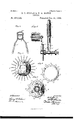
- Figure 1 is a view of a complete bicycle, partly in side elevation and partly in vertical section.
- Fig. 2 is a view, partly in top plan and partly in horizontal section, showing the forks B C in their relative positions and in connection with certain other parts of the machine, the plane of section being through the line X X, Fig. 1.
- Fig. 3 is a view, partly in front elevation and partly in vertical section, showing aportion of the main frame and of the vertically-oscillating seat-frame and other parts connected therewith.
- Fig. 4c is an oblique section through the line Z Z, Fig. 1.
- FIG. 5 6, 7, 8, and 9 are detail views illustrating the connection of the rear sprocket-wheel F with the hub of the rear wheel of the machine, Fig. 9 being a section through the line Y Y of Figs. 6 and 7.
- Fig. 10 is an enlarged view, partly in side elevation and partly in vertical section, illustrating the brake mechanism mounted on and operated by the shaft of the main sprocketwheel F.
- a A are the front and rear wheels, respectively, of a bicycle, said wheels being loosely mounted on their axles a a, the front wheel being of ordinary construe tion and the rear wheel also being of ordinary construction except as to its hub, which has certain peculiarities, whose nature and purpose are hereinafter fully set forth.
- a backbone B of ordinary tubular form, is provided at its rear end with two members B B, forming a fork whose ends are fastened to the axle a of the rear wheel, and a slightly-oblique standard B" is journaled in the front end of the backbone, and is providedwith afork whose lower ends are fastened to the front axle a.
- the backbone B and fork B are strengthened by means of oblique braces B extending forward and upward from the rear ends of the members B, and an oblique brace 13, extending back- Ward and upward from a point on the backbone in front of the junction of the backbone with the members B, the backbone and the braces B" B being bound together and formed into a solid truss by a short standard B, extending upward from the backbone to the junction of the braces.
- This connecting-standard is U-shaped in horizontal section, its rear edge being open, and the braces 13 are joined together at their front ends and bent to coincide with the inner surface of the standard, as illustated in Fig.
- the backbone B, fork B, braces 13' 13, open standardB", and swiveled standard B. form the main frame of the machine, and this frame supports the seat and the operating mechanism in the manner hereinafter described.
- a vertically-oscillating seat-supporting frame made up of two lower members C, whose front ends are rigidly fastened to and connected by a tubular shaftbox C, two oblique braces C extending upward and forward from the rear ends of the members C, and a standard D, rigidly connecting the box C with the front ends of the braces C.
- the rear end of the oscillating frame lies between the members B" of the main frame, and is pivoted in said members in such a way as to allow slight adjustment of the point of connection of the two frames for the purpose of moving the oscillating frame forward or back with reference to the main frame.
- That portion of the standardD between the box C and the front ends of the braces C isan arc of a circle having for its center the pivot of the oscillating frame, and lies partly within and partly above and below the standard B' of the main frame.
- the curved standard D is in the main cylindrical in form, but is provided with two squared portions (1 d, fitted closely and slid ICO ing freely up and down in guides in the main frame, as illustrated in Figs. 2 and 4:, the squared portions of the standard being so placed in the guides in the main frame as to permit the adjustment from front to rear provided for by the manner of pivoting the oscillating frame to the main frame.
- a stop 0 is rigidly fastened to the standard D at the upper end of the curved portion referred to, and a spring S is interposed between this stop and the upper surface of the standard B" of the main frame, thus supporting the oscillating frame in its normal position and offering a yielding resistance to its downward movement with reference to the main frame.
- the standard D extends vertically upward from the upper end of the curved portion referred to, and supportsjati its upper end a seatj adjustably fastened to it in the ordinary manner and for the ordinary purpose.
- a shaft E In thebox O" at the front end of the oscillating frame isjournaled a shaft E, the box being provided with enlarged chambers O, for receiving ball or roller bearings of ordinary construction, and on this shaft are rigidly keyed or otherwise'fastened two cranks E f and a sprocket-wheel F.
- a second sprock- Iet-wlreel F is mounted on the rear aide a of the machine, and a chain F connects the two sprocket-wheelsand transmits the rotation of the driving-sprocket F to the driven sprocketewheel F.
- the adjustment of the oscillating frame with reference to the -main frame in the manner hereinbefore described provides for increasing or decreasing the distance between the sprocket-wheels, and thus renders it possible to tighten or loosen the chain without changing the position of either of the axles a a of the machine.
- G is the hub of the rear wheel of the machine, and is provided on its outer face with a hollow boss g, formed with camshaped peripheral notches g.
- the ring G encircles the boss 9 and. carries in suitable slots aseries of balls or rollers g, corresponding in relative positions with the notches g of the boss.
- the sprocket-ring F encircles the ring G, its inner circumference being in contact with the balls or rollers g.
- a spring S lying partly in a groove g in the face of the hub G, and partly ,in a corresponding and with the outer surface of the boss 9.
- Theaxle a of the wheel lies within the boss 9, and is held in position with reference thereto by means of anti-friction balls or rollers r in the usual manner, and a suitable end plate binds all the parts together. It is, evident that so long as the sprocket-wheel isrotated in the ,direction indicated .by the arrow in Fig.
- the balls ,9" will bind between the sprocket-ring'and the boss g,and thus form a rigid connection of the sprocket-ring and the hub ofthe wheel a, and, on the other hand, if the sprocket-wheel be stopped' and the wheel Acon'tin'ue to move in the same direction as before, the balls grf will drop back into the deeper portions of the v notches, g, and thus disconnect the sprocket-ring and hub.
- the device illustrated anddescribed is a friction-clutch adapted, to connect the sprocket-ring with or disconnect it from the hub, as desired.
- Aspring S is fastened to the brake II and to a lug 71 upon the lower margin of the ring I, and draws the two parts together, thus holding the brake out of contact with the wheel and lifting the lug v) of the ring upward to its limit of motion.
- a cam-shaped notch K is formed in the inner margin of the ring I, and incloses a ball or roller 7t, which impinges upon the surface of the shaftE. It is evident that so long as the shaft E turns in the direction indicated by the arrow in Fig.
- the ball or roller 75 will be loose in the notch in which it lies and the ring I will be disconnected from the shaft E; but that if the rotation of the shaft be reversed the ball or roller will drop down into the narrow lower end of the notch and bind the ring and shaft together, thus pressing the lug i of the ring downward and forcing the brake against the wheel.
- This is in fact a friction-pawl arrangement adapted to leave the ring free from the shaft so long as the latter turns in the direction indicated by the arrow, but to rigidly connect the ring and shaft whenever the motion of the latter is reversed.
- This construction not only does away with a considerable part of the operating mechanism, but it also enables the operator to set the brake by the reverse movement of the cranks, which, as has been said before, is naturally the first movement made by the operator when he desires to stop the machine.
- This feature of construction is not only advantageous itself, but it is especially adapted for use with mechanism permitting the stopping or reversal of the cranks while the wheels of the machine are in motion, since its combination with such mechanism enables the operator to, instantly stop the cranks and put his weight upon the brakeoperating mechanism.
- a bicycle the combination, with the wheels and their axles, of a frame supported by and connecting the axles, a driving-shaft supported by the frame and provided with means for its rotation, a brake adapted to be pressed against the rim of one of the wheels of the machine, and means connecting said drivin -shaft with the said brake, whereby the backward rotation of the shaft presses the brake against said wheel-rim, substantially as and for the purpose set forth.
Landscapes
- Handcart (AREA)
Publications (1)
| Publication Number | Publication Date |
|---|---|
| US418142A true US418142A (en) | 1889-12-24 |
Family
ID=2487065
Family Applications (1)
| Application Number | Title | Priority Date | Filing Date |
|---|---|---|---|
| US418142D Expired - Lifetime US418142A (en) | stotee |
Country Status (1)
| Country | Link |
|---|---|
| US (1) | US418142A (fr) |
-
0
- US US418142D patent/US418142A/en not_active Expired - Lifetime
Similar Documents
| Publication | Publication Date | Title |
|---|---|---|
| US446671A (en) | Tricycle | |
| US483495A (en) | Tricycle | |
| US749153A (en) | Bicycle with rowing attachment | |
| US589705A (en) | Bicycle training-machine | |
| US1150227A (en) | Motor or velocipede skate. | |
| US446670A (en) | Tricycle | |
| US486687A (en) | Bicycle | |
| US397348A (en) | Tricycle | |
| US670608A (en) | Bicycle. | |
| US618652A (en) | John engel | |
| US390916A (en) | Bicycle | |
| US249207A (en) | smith | |
| US258559A (en) | Bicycle | |
| US331113A (en) | Velocipede | |
| US622085A (en) | Third to jacob e | |
| US481883A (en) | Abraham yost and fernando yost | |
| US685086A (en) | Cycle propelling mechanism. | |
| US701642A (en) | Seeder. | |
| US402460A (en) | Bicycle | |
| US92485A (en) | Improved velocipede | |
| US233691A (en) | palmer | |
| US396854A (en) | bowen | |
| US595661A (en) | Bicycle driving m echanism | |
| US260887A (en) | Velocipede | |
| US550520A (en) | Railway-tricycle |