US417841A - Car beake - Google Patents
Car beake Download PDFInfo
- Publication number
- US417841A US417841A US417841DA US417841A US 417841 A US417841 A US 417841A US 417841D A US417841D A US 417841DA US 417841 A US417841 A US 417841A
- Authority
- US
- United States
- Prior art keywords
- lever
- brake
- levers
- wheel
- power
- Prior art date
- Legal status (The legal status is an assumption and is not a legal conclusion. Google has not performed a legal analysis and makes no representation as to the accuracy of the status listed.)
- Expired - Lifetime
Links
- 238000010276 construction Methods 0.000 description 3
- 208000027697 autoimmune lymphoproliferative syndrome due to CTLA4 haploinsuffiency Diseases 0.000 description 1
- 150000001768 cations Chemical class 0.000 description 1
- 238000009408 flooring Methods 0.000 description 1
- 229940110676 inzo Drugs 0.000 description 1
- 230000002093 peripheral effect Effects 0.000 description 1
- 239000002699 waste material Substances 0.000 description 1
Images
Classifications
-
- F—MECHANICAL ENGINEERING; LIGHTING; HEATING; WEAPONS; BLASTING
- F16—ENGINEERING ELEMENTS AND UNITS; GENERAL MEASURES FOR PRODUCING AND MAINTAINING EFFECTIVE FUNCTIONING OF MACHINES OR INSTALLATIONS; THERMAL INSULATION IN GENERAL
- F16D—COUPLINGS FOR TRANSMITTING ROTATION; CLUTCHES; BRAKES
- F16D55/00—Brakes with substantially-radial braking surfaces pressed together in axial direction, e.g. disc brakes
- F16D55/24—Brakes with substantially-radial braking surfaces pressed together in axial direction, e.g. disc brakes with a plurality of axially-movable discs, lamellae, or pads, pressed from one side towards an axially-located member
- F16D55/26—Brakes with substantially-radial braking surfaces pressed together in axial direction, e.g. disc brakes with a plurality of axially-movable discs, lamellae, or pads, pressed from one side towards an axially-located member without self-tightening action
- F16D55/36—Brakes with a plurality of rotating discs all lying side by side
- F16D55/40—Brakes with a plurality of rotating discs all lying side by side actuated by a fluid-pressure device arranged in or one the brake
Definitions
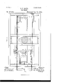
- Figure l is a plan view of so much of a car-truck as is necessary to show my improvement applied to the brake-beams on the outer sides only of 2O the truck-wheels
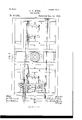
- Fig. 2 is a similar view showing the arrangement of parts for application to brake-beams on both the outer and inner sides of the wheels.
- Fig. 3 represents a transverse section through the car-flooring, showing the clutch-levers in elevation and the chain-wheel in section.
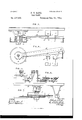
- Eig. 4t is a plan View of the chain-wheel, clutch-levers, and stops for the latter detached.
- Fig. 5 is a detail side view of the weighted leverstops.
- Fig. 6 is a similar view to Eig.
- Eig. 7 is a side elevation ofthe chai n-wheel and pushbar shown in Fig. 2.
- a and A indicate portions of the truckframe, which may be of any usual or preferred construction, and B and B' (referring to Eig. l) brake-beams suspended from or supported on said frame in any usual manner.
- the upper end of the lever O has a rod f connected with it, the op- 6o posite end of which Arod is connected with a transverse iioating lever E, pivoted at or near the center of its length to a rod g, which at its other end is connected in any usual manner with the piston-rod of the steam or air cylinder or other source of power for operating the brakes.
- the opposite end of the lever E is connected by a rod f and chain f2 with the brake-staff or hand-wheel shaft G in the usual manner.
- the wheel or pulley is provided with a peripheral flange Z, and the leverK has one end of a second lever K pivoted to it on its lower face at a point 71; at or near midway between the flange Z and the shaft I.
- the lever K is provided on its end adjacent to the pivot kwith a pendent longitudinal rib 7c,whieh has Ioo a transverse slit or groove k2 formed in it of a width to conformto the thickness of the flange lof the wheel L, adapting said rim or ange to move in said groove when the lever K lies in the same vertical plane with and directly under the lever K, but when the lever K is moved out of the vertical plane of the lever K, turning on its pivotal connection 7c therewith, the side walls of the slot or groove 7a2 are thrown into oblique relation to and are thereby caused to bite or grasp the rim, and then, by a further Y vibration of the lever K carrying with it lever K, both levers swinging on the bolt or
- the lever K is connected by a rod on and chain m with the end of lever F, connected withv The pivot or shaftv the hand-wheel shaft G.
- I on which the wheel L is journaled and to which one end of the lever K is pivoted, is located on one side of the longitudinal center of the car-body, to bring the inner side of the lwheel L nearly into the vertical plane of the rod f, and chains n 'n' have their adjacent ends connected with said wheel or pulley, wrapping or partly wrapping it, and passing on its inner side in opposite directions; or it may be a single chain passing around and secured to said wheel, the opposite ends being attached one to the lever C at its upper end and the other to the end of the floating lever F, connected with said lever C by the rod f, as explained.
- the stops p and p are made in the form of levers pivoted in suitable brackets p2 on the car-bottom and provided with weights p3, which hold them in the required position to act as stops, but allow them to vibrate or yield as the levers are acted upon for applying the brakes.
- light springs q q are substituted for the weighted levers, said springs connecting the ends of the leversK and K with a bracket or brackets q2 on the car-frame.
- the lever F acting first on the lever K overcomes the stop p and draws the lever K out of line or out of the plane of lever K, the stop p holding the latter back until the lever K has clutched the rim of wheel L, when the lever K moves with the lever K turning on the shaft I, and overcoming the stop p the two levers move together, operating the wheel L and thereby operating through the chain m on the brake-lever C.
- the chain n connecting the wheelL with the floating lever F, permits the movement of the latter under the action of the rod g, through which power is applied.
- Fig. 2 the clutch-lever and chain-wheel arrangement, above described, is shown adapted to a truck in which brake-beams are applied on the inner adjacent sides of the wheels as Well as on the outer sides thereof.
- B and B indicate the outer brake-beams and B2 and B3 the inner brake-beams;
- C and C' the upright levers connected with the outer brake-beams, and
- C2 and C3 the levers connected with the beams B2 and B3.
- the lever C is connected by a rod D with the lever C3, and the lever C2 is connected by a similar rod D2 with the lever C for operating said levers C3 and C and the brakebeams connected therewith.
- the end of the lever F', carrying the pulley f4 has one end of a rod or bar S pivoted to it, the opposite end of said rod slidingin a swiveling loop or eye t, pivoted to a bracket T, pendent from the car-body, or secured to other suitable support. (See Fig. 7.)
- the chains n and n in this instance instead of connecting to the brake-lever C and floating lever F, are conneeted to the push rod or bar S, extending from opposite directions and being connected to the wheel L, as before.
Landscapes
- Engineering & Computer Science (AREA)
- General Engineering & Computer Science (AREA)
- Mechanical Engineering (AREA)
- Braking Arrangements (AREA)
Description
(No Model.) `3 sheets-'sheet 1.
G.V.R0TE.
, GARBRAKB. No. 417,841. Patented Deo. 24, 1889.
l E Q/ S2 LL.
N Brul.. a u ma n I I 93 1 s 'rf/X,
d; v 727677157, y i 4/ -L E l wmf/m 4mm@ (No Model.) 3 Sheets-Sheet 2. C. V. ROTE.
GAR' BRAKE. 110.417,841. @1 Patented Deo. 24,V 1889.
Il I
FIC-3 2- H H Il Il Il Il jwemfwzw 47 Q22 H51@ (No Model.) 3 sheets-sheet 3.
G. V. ROTE. GAR BRAKE.
n. PETERS. Plwwrmhnmplwr. wamingm. D. C-
UNITED STATES PATENT OFFICE.
CHARLES VICTOR ROTE, OE LANCASTER, PENNSYLVANIA, ASSIGNOR OF ELEVEN-'VELETIIS TO BERNARD J. IWICGRANN AND EUGENE G. SMITH, OF
SAME PLACE.
CAR-BRAKE.
SPECIFICATION forming part of Letters Patent No. 417,841, dated December 24, 1889.
Application filed May 15, 1889. Serial No. 310,837. (No model.)
T all whom, it 171,603/ concern:
Be it known that I, CHARLES Vieron ROTE, a citizen of the United States, and a resident of Lancaster, county of Lancaster, and State of Pennsylvania, have invented a new and useful Improvement in Car-Brakes, of which the following is a full, clear, and exact description, reference being had to the accompanying drawings, making part of this speci- Io cation. My present invention relates to an improvement upon the arrangement of brake mechanism embraced in my application for Letters Patent filed March 2S, 1889, Serial No. 305,069; and it consists in the addition thereto of aclutch-lever and pulley or chain wheel interposed between the actuating-power and the brake mechanism, whereby the power is more fully utilized and greatly increased, inzo stead of being largely lost or wasted, as in the ordinary arrangement of parts heretofore employed.
It also consists in certain details of construction and arrangement of parts, all as hereinafter described and claimed.
In the accompanying drawings, Figure l is a plan view of so much of a car-truck as is necessary to show my improvement applied to the brake-beams on the outer sides only of 2O the truck-wheels, and Fig. 2 is a similar view showing the arrangement of parts for application to brake-beams on both the outer and inner sides of the wheels. Fig. 3 represents a transverse section through the car-flooring, showing the clutch-levers in elevation and the chain-wheel in section.. Eig. 4t is a plan View of the chain-wheel, clutch-levers, and stops for the latter detached. Fig. 5 is a detail side view of the weighted leverstops. Fig. 6 is a similar view to Eig. 5 showing springs instead of4 weights applied for holding the clutch-levers in check; and Eig. 7 is a side elevation ofthe chai n-wheel and pushbar shown in Fig. 2. A and A indicate portions of the truckframe, which may be of any usual or preferred construction, and B and B' (referring to Eig. l) brake-beams suspended from or supported on said frame in any usual manner.
series of perforations e, through any one of which and a perforation in the upper end of the lever C a pin e may be passed for holding the upper end of the .lever C at the de-` sired adjustment. The upper end of the lever O has a rod f connected with it, the op- 6o posite end of which Arod is connected with a transverse iioating lever E, pivoted at or near the center of its length to a rod g, which at its other end is connected in any usual manner with the piston-rod of the steam or air cylinder or other source of power for operating the brakes. The opposite end of the lever E is connected by a rod f and chain f2 with the brake-staff or hand-wheel shaft G in the usual manner.
The parts above described are similar to those now in common use and their operation is well known. It will be readily understood that when power is applied to the lever E for operating the brakes said lever is supported at 7 5 one end through its connection with the brakestaff cr hand-wheel shaft G, and the power being applied at the center of said lever, one half of the power exerted is wasted on said shaft, the other half only being utilized to apply 8o the brakes. The object of my invention is to avoid this waste, and to increase the leverage through which the power is applied, and thereby, if desired, to greatly reduce the amount of power necessary to properly apply the brakes. To the under side of the cariooring frame, (indicated at H, Fig. 3,) or to a suitable bracket h, secured thereto, is secured a pendent bolt or stud shaft I, upon which is pivoted a lever K, and underneath said lever 9o a wheel or pulley L is journaled to turn freely on said shaft, heldin place thereonv by a head or collar on the lower end of the bolt or stud.
.The wheel or pulley is provided with a peripheral flange Z, and the leverK has one end of a second lever K pivoted to it on its lower face at a point 71; at or near midway between the flange Z and the shaft I. The lever K is provided on its end adjacent to the pivot kwith a pendent longitudinal rib 7c,whieh has Ioo a transverse slit or groove k2 formed in it of a width to conformto the thickness of the flange lof the wheel L, adapting said rim or ange to move in said groove when the lever K lies in the same vertical plane with and directly under the lever K, but when the lever K is moved out of the vertical plane of the lever K, turning on its pivotal connection 7c therewith, the side walls of the slot or groove 7a2 are thrown into oblique relation to and are thereby caused to bite or grasp the rim, and then, by a further Y vibration of the lever K carrying with it lever K, both levers swinging on the bolt or shaft I, the wheel L is caused to partially rotate on said shaft with said levers. The levers K and K ext-end transversely underneath the car-body and the free end of.v
the lever K is connected by a rod on and chain m with the end of lever F, connected withv The pivot or shaftv the hand-wheel shaft G. I, on which the wheel L is journaled and to which one end of the lever K is pivoted, is located on one side of the longitudinal center of the car-body, to bring the inner side of the lwheel L nearly into the vertical plane of the rod f, and chains n 'n' have their adjacent ends connected with said wheel or pulley, wrapping or partly wrapping it, and passing on its inner side in opposite directions; or it may be a single chain passing around and secured to said wheel, the opposite ends being attached one to the lever C at its upper end and the other to the end of the floating lever F, connected with said lever C by the rod f, as explained. By now leaving the rod and chain f and f2 slack, as indicated in Fig. l, when power is applied to the lever F for operating the brakes, it is exerted first to take up all slack in the lever and brake connections, and then the power heretofore wasted on the handwheel shaft C is applied to the end of the lever K', which is immediately deflected or drawn out of the vertical plane of the lever K and made to clutch and rotate the wheel L, and the latter, acting through the chains n4 and n on the lever C, not only serves to utilize the power applied to the lever K to the operation of the brakes, but to give increased efficiency thereto proportionate to the length of the long arm of said lever, which is connected to the floating lever F, as compared with the short arm of said lever, conforming to the radius of the wheel L. Suitable yielding stops p p are arranged to hold the levers K and K back in proper position, a fixed stop P serving to prevent their movement backward beyond such position.
In Fig. 5 the stops p and p are made in the form of levers pivoted in suitable brackets p2 on the car-bottom and provided with weights p3, which hold them in the required position to act as stops, but allow them to vibrate or yield as the levers are acted upon for applying the brakes. In Fig. 6 light springs q q are substituted for the weighted levers, said springs connecting the ends of the leversK and K with a bracket or brackets q2 on the car-frame. In operation the lever F, acting first on the lever K overcomes the stop p and draws the lever K out of line or out of the plane of lever K, the stop p holding the latter back until the lever K has clutched the rim of wheel L, when the lever K moves with the lever K turning on the shaft I, and overcoming the stop p the two levers move together, operating the wheel L and thereby operating through the chain m on the brake-lever C. The chain n, connecting the wheelL with the floating lever F, permits the movement of the latter under the action of the rod g, through which power is applied.
It will of course be readily seen that the movement of the power-lever F under the action of the power applied thereto will take up any slack in the brake-connections therewith and seat the brake-shoes in readiness for action prior to any necessary movement of the clutch-levers K and K, and that consequently but slight movement of said levers will be required for applying the desired pressure of the shoes. y
In Fig. 2 the clutch-lever and chain-wheel arrangement, above described, is shown adapted to a truck in which brake-beams are applied on the inner adjacent sides of the wheels as Well as on the outer sides thereof. B and B, as before, indicate the outer brake-beams and B2 and B3 the inner brake-beams; C and C', the upright levers connected with the outer brake-beams, and C2 and C3 the levers connected with the beams B2 and B3. F is the floating power-'lever connected by a rod and chain j" and f2 with the brake-staff:` or hand-wheel shaft, as before; but the opposite end of said lever F, instead of being connected by a rod 'with the brake-lever C, has a sheave or pulley f4 on said end, around which a chain r passes, one end of said chain connecting through a rod r with the brakelever C, and the other end through a rod r2 with the brake-lever C2.
The lever C is connected by a rod D with the lever C3, and the lever C2 is connected by a similar rod D2 with the lever C for operating said levers C3 and C and the brakebeams connected therewith. The end of the lever F', carrying the pulley f4, has one end of a rod or bar S pivoted to it, the opposite end of said rod slidingin a swiveling loop or eye t, pivoted to a bracket T, pendent from the car-body, or secured to other suitable support. (See Fig. 7.) The chains n and n in this instance, instead of connecting to the brake-lever C and floating lever F, are conneeted to the push rod or bar S, extending from opposite directions and being connected to the wheel L, as before. In this construction 'when power is applied to the lever F and it is drawn outward, it acts upon the le ver K and K as above described, and as the wheel L is rotated it acts on the push-bar S, through the chain m', to push the end of the lever F connected therewith outward, thereby, through the chain r and rods r and r2, causing Y on the levers C and C3.
said movement to act on the levers C and C2, and thence through the connections described By this arrangement all the power exerted upon the lever F is utilized by the movement of the latter bodily, and through the aid of the clutch-lever and chain-wheel, as described, to apply the brakes with the added power due to the difference in the lengths of the clutch-lever arms, as above explained. By the arrangement described I am enabled to greatly reduce the power required for the proper application of the brakes.
It will be apparent that as the movement of the chain wheel or pulley is slight a set,- ment may be substituted therefor, and `also that the form of the clutch-levers may be varied without departing from my invention.
Having now described my invention, I claim as new- 1. The combination, With the floating lever, through which power is applied to the brakes and the brake-levers actuated thereby, of the interposed clutch-lever connected with the floating and brake levers, substantially as described. p
2. The combination, in a brake mechanism, of the iioatin'g or power lever, a clutchlever connected therewith, and brake-levers connected to said floating and clutch levers, substantially as described.
3. In a brake mechanism, the chain wheel or pulley, in combination with the clutch-lever pivoted on the shaft of said wheel, and chains connecting` said Wheel and lever with the power and brake levers, substantially as described.
4. The combination in a brake mechanism, of the iioating or power lever, the brakelevers and an interposed lever pivoted at one end and connected to the brake and power levers, substantially as described. Y
5. The combination, in a brake mechanism, of the Boating or power lever, the bralrelevers, and the interposed clutch-lever K K and chain wheel or pulley L, connected to the power-lever and brake-levers, substantially as described.
6. The combination, in a brake mechanism, of the chain wheel or pulley L, the lever K, pivoted to the shaft of said pulley, t-he clutch-lever K', pivote-d to the lever K to engage the Wheel L, the brake-levers connected with said wheel and levers, and stops controlling the movements of the levers K and K', substantially as described.
In testimony whereof I have hereunto set my hand this 13th day of May, A. D. 1889. CHARLES VICTOR ROTE.
Vitnesses:
C. REEsE EABY, JOHN W. APPEL.
Publications (1)
| Publication Number | Publication Date |
|---|---|
| US417841A true US417841A (en) | 1889-12-24 |
Family
ID=2486765
Family Applications (1)
| Application Number | Title | Priority Date | Filing Date |
|---|---|---|---|
| US417841D Expired - Lifetime US417841A (en) | Car beake |
Country Status (1)
| Country | Link |
|---|---|
| US (1) | US417841A (en) |
-
0
- US US417841D patent/US417841A/en not_active Expired - Lifetime
Similar Documents
| Publication | Publication Date | Title |
|---|---|---|
| US417841A (en) | Car beake | |
| US416749A (en) | Gar brake | |
| US414891A (en) | Teen twenty-fourths to bernard j | |
| US384507A (en) | Car-brake | |
| US411547A (en) | Automatic car-brake | |
| US274144A (en) | Car-brake | |
| US422330A (en) | Pierre j | |
| US230181A (en) | Car-brake | |
| US778597A (en) | Slack-adjuster for car-brakes. | |
| US570925A (en) | Slack-adjuster for railway-car brakes | |
| US787643A (en) | Car-brake. | |
| US424773A (en) | Car-brake | |
| US377874A (en) | William b | |
| US440014A (en) | Car-brake | |
| US293319A (en) | Office | |
| US358547A (en) | Pcters | |
| US678298A (en) | Brake mechanism. | |
| US458497A (en) | Car-brake | |
| US751355A (en) | Cab-brake | |
| US142658A (en) | Improvement in car-brakes | |
| US569312A (en) | Car-brake | |
| US381978A (en) | Car-brake | |
| US508316A (en) | Car-brake | |
| US234294A (en) | Car-brake | |
| US356622A (en) | cooke |