US417543A - Grain-meter - Google Patents
Grain-meter Download PDFInfo
- Publication number
- US417543A US417543A US417543DA US417543A US 417543 A US417543 A US 417543A US 417543D A US417543D A US 417543DA US 417543 A US417543 A US 417543A
- Authority
- US
- United States
- Prior art keywords
- receiver
- grain
- bail
- partition
- meter
- Prior art date
- Legal status (The legal status is an assumption and is not a legal conclusion. Google has not performed a legal analysis and makes no representation as to the accuracy of the status listed.)
- Expired - Lifetime
Links
- 238000005192 partition Methods 0.000 description 12
- 240000001973 Ficus microcarpa Species 0.000 description 2
- 239000004927 clay Substances 0.000 description 2
- 229910052570 clay Inorganic materials 0.000 description 2
- 230000003292 diminished Effects 0.000 description 2
- XEEYBQQBJWHFJM-UHFFFAOYSA-N iron Substances [Fe] XEEYBQQBJWHFJM-UHFFFAOYSA-N 0.000 description 2
- 229910052742 iron Inorganic materials 0.000 description 2
- 239000010978 jasper Substances 0.000 description 2
- ATJFFYVFTNAWJD-UHFFFAOYSA-N tin hydride Chemical compound [Sn] ATJFFYVFTNAWJD-UHFFFAOYSA-N 0.000 description 2
Images
Classifications
-
- G—PHYSICS
- G01—MEASURING; TESTING
- G01G—WEIGHING
- G01G13/00—Weighing apparatus with automatic feed or discharge for weighing-out batches of material
Description
(No Model.) 2 Sheets-Sheet 2.
A. E. CLAY. GRAIN METER.
een 15E b fs? H1 N YB m v e /f//l/ {1l/l] umu ".s 11111, mi 1.,f *1l '@111111 111 1 1111 UNITED STATES PATENT OFFICE.
ANSON E. CLAY, OF NE\VBURG, IOVA.
GRAIN-METER.
SPECIFICATION forming part of Letters Patent No. 417,543, dated December 17, 1889.
Application filed June 5, 1889. Serial No. 313,163. (No model.) a
To all whom it may concern: through a slot f (see Fig. 2) in a standard F, Be it known that I, ANSON E. CLAY, a citiwhich projects upwardly from a frame-bar Zen of the United States, residing at New/burg, a, the ends ot which slot limit the extent of 5 5 in the county of Jasper and State of Iowa, the upward and downward swing of the ends 5 have invented certain new and useful Imof the bail, and thereby limit the upward and provements in Grain-Meters, of which the downward movement of the grain-receiver B. following is a specilication. Angle-plates G have vertical faces g, which This invention relates to grain-meters ot slide against angle -plates f fixed to the 6o that class in which the grain is received from trame-bars a, (see Figs. 2, 3, and 5,) to pre- 1o a thrashing-machine or other continuous devent any lateral movement of the receiver B livery in a vertically-reciprocating box or rewith reference to detent-plates I-I, one of ceiver, in which it is automatically weighed which is iiXed to and projects below each and discharged in given quantities, as desired, frame-bar a. The corners 7L 7L of these de- 65 and from opposite sides alternately of a tent-plates H are preferably rounded ott, as
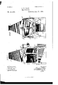
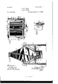
t 5 swinging partition in said receiver; and the shown at Figs. 2 and 3, and constitute the deinvention consists in constructions and comtents proper. binations hereinafter described and claimed. The partition-board I extends across the in- In the accompanying drawings, which illusterior of the receiver B from one of its verti- 7o trate my invention, Figure 1 is a side elevacal sides b to the other, and is suspended zo tion; Fig. 2, an end elevation; Fig. 3, a secfrom said sideso by pivot-boltst'in such mantional elevation in the line 3 3 in Fig. l. Fig. ner that it can swing on the pivots t to bring 4 is a top plan showing the receiver with its its lower end in close contact with either of upper part removed, and showing the swingtwo opposite sides b" of the open lower end 75 ing partition or division board in section 5 of the receiver. The lower end of the parti- Fig. 5, an enlarged detail of parts hereinafter tion-board I extends slightly below the lower described. end of the receiver B and carries a plate one The operating parts of the meter are carend .I of which projects from each edge of ried in a frame A, formed of vertical posts a, the board I such distance that each may en- 8o connected by transverse posts c a, and gage with the adjacent detent h or h, as
3o strengthened by braces c. The grain-rehereinafter described. The upper end of the ceiver B is formed of two sides b, vertical and board I is covered with tin or sheet-iron, parallel at their lower parts, and inclined towhich is turned outwardly to torni iianges t" ward each other at their upper parts, and its at the sides ot said board. other two sides tapered toward its lower end The trough K, with an inclined discharg- 35 b and toward its upper end b, where said ing-bottom 7c, is suspended from the frame A sides are iiared outwardly, as shown. The beneath the open lower end of the receiver receiver B has a strap c at each of its sides, B by hooks 7.5', and may be hung as shown from each ot which projects a stud or pivotor in an opposite direction thereto by the bolt c. The pivots c are journaled one in same hooks, in order to receive the measured 4o each end of a bail D, each arm or member d grain from the receiver B and to discharge it of which bail carries a pivot-bolt C These into any desired receptacle.
bolts d are journaled one in each of the In use the apparatus is located so as to remetal platesc which extend upwardly and ceive the grain at its upper end from a form part of standards 61, that project upt'hrasher or any other source with a continu- 45 wardly from the bars a. The bail D has an ous supply; and to illustrate its operation I arm D extending outwardly, with a dependwill suppose the partition-board I to be standing hook e, on which weights E maybe placed, ing, as shown by full lines at Fig. 3, with the as desired. Thus the receiver B is suspended lugs J at its lower end engaged with the de- IOO by the pivots c from one end of the bail D, tents h to hold it in said position, and that 5o which bail is in turn pivotally suspended on weights E are placed on the beam D to balthe bolts c and provided at its other end ance. the weight of the receiver B, and also with the weights E. The arm D passes balance such weight or quantity of grain as it is desired to measure in each charge of said receiver. Vhen such quantity has entered t-her receiver, it will overbalance the weights E andv the receiver will drop to the position shown by dotted lines at same tigure. This dropping or lowering oi' the receiver will carry the lugs .I below the plate I-I, and thus release said lugs from the detents, and the weight of the grain on the lower end of the partition I will then swing it over into the position shown by dotted lines at same figure and allow the grain to escape, and asJ the grain escapes, its weight being diminished, the weights E will again raise the receiver to its highest position and thereby bringY the lugs .I into engagement with the detents 7L,while the partition is still held in its last-described position by the escaping grain. The same operation is then repeated by the partition I being swung in the opposite die rection to that last described.
The apparatus may be located to discharge the grain from the spout K into any suitable receiver, and a registering apparatus ot' any preferred kind may be attached to any desired moving part of the apparatus to register the number of discharges of grain from the receiver B.
The upper part of the receiver B is formed separately from its lower part on the line (see Fig. 3,) and the two parts are held together by hooks and eyes L. (See Fig. l.) The hooks Il may be disengaged and the upper part of the receiver removed for access to its interior to remove or repair the partition I, or for any other purpose.
I claim as new and desire to secure byLetters Patent-v l. In a grain-meter, the combination of the frame having the angle-plate g and plate H, provided with detents h and 7i', the bail D, pivotallysupported by the frame and hav ing the weights E, the receiver B, suspended on the bail D and having the angle-plate G g, and the partition-board I, exten d ing slightly below the end of the receiver and having a plate with projecting end J, substantially as described.
2. In a graiumeter, the combination oi the frame having the angle-plate g and plate Il, provided with detents 7L and 7L', the bail D, pivotally supported by the f'ame and having the weights E, the receiver B, suspended on the bail D and having the angle-plate G g, the partition-board I, extending slightly below the end of the receiver and havin g a plate with projecting ends J, and a trough K, suspended from the frame and hanging below the bottom of the receiver, substantially as described.
In testimony whereof I alix my signature in presence of two witnesses.
ANSON E. CLAY. lVitnesses:
WM. MEANOR, J. T. GEssNA.
Publications (1)
| Publication Number | Publication Date |
|---|---|
| US417543A true US417543A (en) | 1889-12-17 |
Family
ID=2486469
Family Applications (1)
| Application Number | Title | Priority Date | Filing Date |
|---|---|---|---|
| US417543D Expired - Lifetime US417543A (en) | Grain-meter |
Country Status (1)
| Country | Link |
|---|---|
| US (1) | US417543A (en) |
-
0
- US US417543D patent/US417543A/en not_active Expired - Lifetime
Similar Documents
| Publication | Publication Date | Title |
|---|---|---|
| US417543A (en) | Grain-meter | |
| US28568A (en) | Improvement in machines for weighing and bagging grain | |
| US375163A (en) | Grain-weighing apparatus | |
| US403396A (en) | Grain-meter | |
| US976069A (en) | Automatic weighing-cabinet. | |
| US825864A (en) | Weighing-machine. | |
| US1119059A (en) | Grain-measuring device. | |
| US344395A (en) | Grain-tally | |
| US1072897A (en) | Bag-measuring apparatus. | |
| US502347A (en) | Measuring-vessel | |
| US675771A (en) | Automatic weighing-machine. | |
| US323371A (en) | spencer | |
| US303300A (en) | Hanging platform-scale | |
| US377513A (en) | Chaeles e | |
| US444709A (en) | Grain-meter | |
| US286934A (en) | kuhlman | |
| US290240A (en) | tuexee | |
| US763560A (en) | Weighing-machine. | |
| US360154A (en) | Grain-weighing apparatus | |
| US192610A (en) | Improvement in coal-elevators | |
| US436854A (en) | Automatic grain-weighing scales | |
| US1019685A (en) | Combined bag-holder and weighing-scale. | |
| US289784A (en) | stokeb | |
| US731713A (en) | Conveyer. | |
| US261516A (en) | Grain-meter |