US416632A - Incandescent electric lamp - Google Patents
Incandescent electric lamp Download PDFInfo
- Publication number
- US416632A US416632A US416632DA US416632A US 416632 A US416632 A US 416632A US 416632D A US416632D A US 416632DA US 416632 A US416632 A US 416632A
- Authority
- US
- United States
- Prior art keywords
- lamp
- coil
- coils
- wire
- current
- Prior art date
- Legal status (The legal status is an assumption and is not a legal conclusion. Google has not performed a legal analysis and makes no representation as to the accuracy of the status listed.)
- Expired - Lifetime
Links
- 239000011810 insulating material Substances 0.000 description 5
- 230000001105 regulatory effect Effects 0.000 description 4
- OKTJSMMVPCPJKN-UHFFFAOYSA-N Carbon Chemical compound [C] OKTJSMMVPCPJKN-UHFFFAOYSA-N 0.000 description 1
- 241000131894 Lampyris noctiluca Species 0.000 description 1
- 229910052799 carbon Inorganic materials 0.000 description 1
- 230000003247 decreasing effect Effects 0.000 description 1
- 230000000694 effects Effects 0.000 description 1
- 230000005611 electricity Effects 0.000 description 1
- 239000011521 glass Substances 0.000 description 1
- 239000000463 material Substances 0.000 description 1
- 239000002184 metal Substances 0.000 description 1
- 238000000034 method Methods 0.000 description 1
- 230000000284 resting effect Effects 0.000 description 1
- 239000007787 solid Substances 0.000 description 1
Images
Classifications
-
- H—ELECTRICITY
- H01—ELECTRIC ELEMENTS
- H01C—RESISTORS
- H01C10/00—Adjustable resistors
- H01C10/30—Adjustable resistors the contact sliding along resistive element
- H01C10/38—Adjustable resistors the contact sliding along resistive element the contact moving along a straight path
Definitions
- My present improvements in electric lamps relate, as will hereinafter appear, to devices whereby the intensity of the electric current supplied to individual lamps may be regulated at will.
- the design of my present invention is to so construct electric lamps that with a single incandescent wire or light-giving carbon in a lamp the degree of brilliancy and light-giving properties of each lamp may be readily and instantaneously regulated and changed at will, so that the light from such lamp may be at any time of any degree of brightness desired.
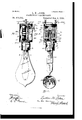
- Figure 1 represents a front elevation, partly in section, of an incandescent lamp constructed according to my invention.
- Fig. 2 represents an end elevation thereof, partly in section.
- Fig. 3 represents a transverse section taken on the line a a of Fig. 2.
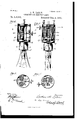
- Fig. 4 represents a front elevation of so much of an incandescentlamp as will serve to show one of the various f0rms of currentregulating devices that may be employed in carrying out my present improvements.
- Fig. .5 represents an edge view of such a lamp, partly in section, andshowing still another form of current-regulator.
- Fig. 6 represents a transverse section taken on the line b b of Fig. 4:
- Fig. 7 represents a transverse section taken on the line 0 c of Fig. 5.
- the lamp-socket is provided at top and bottom with a disk of insulated material, between which are supported a pair of resistance-coils, which may' be secured to or within suitable recesses in the insulated disks in any suitable mannerfor instance,
- 1 represents an ordinary globe or bulb within which the incandescent-light wire 2 is contained, said wire being coupled in the customary manner to connecting and currentconveying wires 3, passing through a solid glass teat 4, depending within the globe.
- the lamp-socket has a depending ring 5, provided with bayonet-joints 6 in its inner face, with which pins 7 on the ring 8, encircling the neck of the globe, engage to removably secure the lamp in its socket, 'the lamp being passed up within the socket with the pins 7 traveling along the vertical portions of this disk to the rim of the ring 5 passes a hollow stud or pin 10, through which the mainline wire 11, conveying the current from the negative pole, passes, as shown in Fig. 2 of I00 the drawings, to that part of the socket adjacent the current-conveying wire on that side of the lamp, this negative-polewire, as clearly shown in Fig.
- coils 16 and 18 and the insulating-disks 9 and 15 are connected together in the position shown in any suitable manner-as, for instance, through the medium of screw-threads upon the respective ends of said coils or coil-bobbins en a in in screw-threads in suitable sockets in the respective disks.
- a wire 20 From the top of the coil 18 depends a wire 20, the lower end of which is attached to a spring-plate 21, secured to the lower insulated disk 9, with its inner end projecting over a central orifice in said disk, within which an upwardly-projecting portion of the lamp enters into contact with said springplate upon the lamp being inserted in its socket.
- WVhile I prefer to employ such plate in spring form to insure its always rei'naining incont-act with the top of the lamp or with a metallic extension thereof adapted to convey the electric current to the con veying-wire extending upward within said lamp-extension, as shown in Fig.
- I employ a strip of metal 22, curved at each end to embrace, or partly embrace, the respective resistance-coils and readily reciprocate thereon, so as to connect said coils, and when in operative position transmit the current from the positive pole from the coil 16 to the coil 18, from whence it tlows through the wire 20 to the plate 21, so as to light the lamp.
- This coilconnecting strip 22 is adapted to reciprocate vertically along the respective coils 16 and .18, so as to graduate the intensity-of or put out the light, as maybe desired.
- This reciprocal adjustment of said strip may be accomplished in a variety of wayssuch, for instance, as shown in Figs.
- a plane-faced post or rod 28 may be employed and the coil-connecting strip 22 slid therealong by means of the key provided with a socket 29, through which said post or rod 28 passes; or, as shown in Figs. 6 and 7 of the drawings, a toothed rack or bar 30, carrying the coil-connecting strip 22, may be interposed between the coils, and it and the strip 22 reciprocated on turning the key 26, by means of a cog-wheel carried by said key ongaging with said toothed rack.
- the current from the negative pole passes from the binding-post 12 to wire 11, to wire 3, to filament 2, to spring 21, to wire 20, and thence to resistance-coil 18, and the lamp remains unlighted.
- the connectingstri p 22 is in engagement with the wire of the coils 16 18, the course, of the current from the negative pole is the same as has just been described, except that it then passes from the V coil 18 to connecting-strip 22, to coil 16, and
- the key 26 is turned to bring the coil-connecting strip 22 to, or near to, the top of the coils, and by similarly lowering said strip, and thereby increasing the distance of .travel of the current, the brilliancy and intensity of the light is correspondingly and proportion ately decreased.
- the coil-connecting strip 22 is drawn down to the insulated base portions 17 20 of the coil-bobbins, whereby connection between the respective coils, and also between the electrical current from the respective poles, is cut off and the lamp darkened. It will thus be apparent that the putting out of and the regulation of the light of each individual lamp in a circuit can be readily and expeditiously accomplished by any unskilled person by my arrangement of devices.
- a weak glowworm light is produced in the lamp suitable for night use in sleeping and other apartments, while by raising said coil-connecting strip along the coils, as indicated in Figs. 1, 2, and at of the drawings, the brilliancy of the light in the lamp is correspondingly increased, such increase of light being instantaneously producible at will, as will be readily understood.
- An independent socket for incandescent lamps consisting of an outer shell and a depending ring adapted to removably connect with the lamp and contained within said socket, and in combination therewith and with the customary exhausted globe, a pair of insulated disks, one connected with the socketattaching ring and the other with the top of the socket, a metallic contact-plate carried by the lower disk and connecting wit-h the current-conveying wires in the lamp, a pair of resistance-coils support-ed between and within said disks and having exposed lower portions of insulating material, a slide adapted to connect said coils, a rod and key connected with said slide for the purpose of securing the reciprocation thereof vertically along said coils, wires connecting, respectively, the negative pole and the incandescent wire and the positive pole and one of said coils, and a wire connecting the other coil and the metallic contact-plate carried by the lower disk, substantially as and for the purpose set forth.
- An incandescent lamp consisting of a bulb or globe, an incandescent wire or filament therein, a socket having an upper and a lower insulated disk, a pair of resistancecoils supported between said disks and having insulated lower ends, circuit-wires connecting the positive pole and one of said coils and the circuit connections to the negative pole and the other coil, a metallic strip adapted to engage with and connect the respective coils, a bearing-support'for said strip having bearing within the lamp-socket, and a key adapted to reciprocate said coil-connecting strip on the support and along the coils, so as to either increase or diminish or put out the light, as desired, substantially as set forth.
Landscapes
- Engineering & Computer Science (AREA)
- Microelectronics & Electronic Packaging (AREA)
- Non-Portable Lighting Devices Or Systems Thereof (AREA)
Description
(No Model.) 2 Sheets--Sheet 1. LE. LEBEB.
, INOANDESGENT ELECTRIC-LAMP. No. 416,682. Patented Dec. 8, 1889.
Ill!
2 Sheets Sheet 2.
I No Model.)
H. LEBER. I INGANDESOENT ELECTRIG LAMP- No. 416,632, I Patented Dec. 3, 1889.
UNITED STATES PATENT OFFICE.
LUTHER H. LEBER, OF YORK, ASSIGNOR OF ONE-HALF TO GEORGE E. ANDERSON, OF PITTSBURG, PENNSYLVANIA.
INCANDESCENT ELECTRIC LAMP.
SPECIFICATION forming part of Letters-Patent No. 416,632, dated December 3, 1889.
Application filed July 10, 1889. Serial No. 317,014. (No model.)
To aZZ whom it may concern Be it known that I, LUTHER II. LEBER, a citizen of the United States, residing at York, in the county of York and State of Pennsylvania, have invented certain new and useful Improvements in Electric Lamps; and I do hereby declare the following to beafull, clear, and exact description of the invention, such as will enable others skilled in the art to which it appertains to make and use the same.
My present improvements in electric lamps relate, as will hereinafter appear, to devices whereby the intensity of the electric current supplied to individual lamps may be regulated at will.
The design of my present invention is to so construct electric lamps that with a single incandescent wire or light-giving carbon in a lamp the degree of brilliancy and light-giving properties of each lamp may be readily and instantaneously regulated and changed at will, so that the light from such lamp may be at any time of any degree of brightness desired.
In the accompanying drawings, which represent the principle of my present invention and some of the modes whereby the same is carried into effect, Figure 1 represents a front elevation, partly in section, of an incandescent lamp constructed according to my invention. Fig. 2 represents an end elevation thereof, partly in section. Fig. 3 represents a transverse section taken on the line a a of Fig. 2. Fig. 4 represents a front elevation of so much of an incandescentlamp as will serve to show one of the various f0rms of currentregulating devices that may be employed in carrying out my present improvements. Fig. .5 represents an edge view of such a lamp, partly in section, andshowing still another form of current-regulator. Fig. 6 represents a transverse section taken on the line b b of Fig. 4:, and Fig. 7 represents a transverse section taken on the line 0 c of Fig. 5.
Briefly stated, the lamp-socket is provided at top and bottom with a disk of insulated material, between which are supported a pair of resistance-coils, which may' be secured to or within suitable recesses in the insulated disks in any suitable mannerfor instance,
pass the one through a suitable contact-post on the upper insulated disk and through the latter to the lamp, and the other through another similarly-positioned contact-post to one of the coils, one strand of the wire from the other coil extending from the upper end thereof down to a spring contact-plate located in the upper face of the lower disk, a contact plate or strip adapted to engage the coils and transmit the current from the one to the other, and means for reciprocating said contactstrip along the resistance-coils, so as to regulate the distance of travel along said coils of the electric current before reaching the incandescent wire, and thereby increase or diminish the volume of light, or put out the lamp, as may be desired.
Referring to the accompanying drawings, 1 represents an ordinary globe or bulb within which the incandescent-light wire 2 is contained, said wire being coupled in the customary manner to connecting and currentconveying wires 3, passing through a solid glass teat 4, depending within the globe.
The lamp-socket has a depending ring 5, provided with bayonet-joints 6 in its inner face, with which pins 7 on the ring 8, encircling the neck of the globe, engage to removably secure the lamp in its socket, 'the lamp being passed up within the socket with the pins 7 traveling along the vertical portions of this disk to the rim of the ring 5 passes a hollow stud or pin 10, through which the mainline wire 11, conveying the current from the negative pole, passes, as shown in Fig. 2 of I00 the drawings, to that part of the socket adjacent the current-conveying wire on that side of the lamp, this negative-polewire, as clearly shown in Fig. 2,passing from the con tact-post 12 vertically to the hollow stud 10 without coming in contact with either resistance-coil; consequently the current of electricity from the negative pole is by this arran gement conveyed directly to the lamp. The other main-line wire 13, connected with the positive pole, passes from the contact-post 14 through the top disk 15, of insulating mate rial, to the coil 16. Up to this time it will be noticed that while the current from the negative pole isin communication with the incandescent wire 2 the current from the positive pole passes to the coil 16, where, by reason of said coil resting upon the insulated disk 0, and by the further reason that said coil has at its-bottom an exposed collar or ring 17, of insulating material, said current from the positive pole remains, there being up to this time no communication between the negative and positive poles. 18 represents another resistance-coilhavinga base 19, of insulating material. These coils 16 and 18 and the insulating-disks 9 and 15 are connected together in the position shown in any suitable manner-as, for instance, through the medium of screw-threads upon the respective ends of said coils or coil-bobbins en a in in screw-threads in suitable sockets in the respective disks.
I will now proceed to describe the manner in which, according to my present invention, I secure the uniting of the current from the positive and negative poles and the regulation of the intensityof the light of individual incandescent lamps.
From the top of the coil 18 depends a wire 20, the lower end of which is attached to a spring-plate 21, secured to the lower insulated disk 9, with its inner end projecting over a central orifice in said disk, within which an upwardly-projecting portion of the lamp enters into contact with said springplate upon the lamp being inserted in its socket. WVhile I prefer to employ such plate in spring form to insure its always rei'naining incont-act with the top of the lamp or with a metallic extension thereof adapted to convey the electric current to the con veying-wire extending upward within said lamp-extension, as shown in Fig. 2 of the drawings, it is manifest that such contact-plate could be so constructed and positioned as to insure contact with the lamp and wire therein without the aid of a spring, In this condition of afiairs it will be noticed that the current from the negative pole is directly in contact with the light or incandescent wire 2, and the current from the positive pole is in contact with the resistance-coil16, while the coil 18 remains inert by reason of its being up to the present time in contact only with the current from the negative pole.
To secure the union of the current from both poles and the passage 01' the current from the positive pole to the light-wire 2 within the globe, I employ a strip of metal 22, curved at each end to embrace, or partly embrace, the respective resistance-coils and readily reciprocate thereon, so as to connect said coils, and when in operative position transmit the current from the positive pole from the coil 16 to the coil 18, from whence it tlows through the wire 20 to the plate 21, so as to light the lamp. This coilconnecting strip 22 is adapted to reciprocate vertically along the respective coils 16 and .18, so as to graduate the intensity-of or put out the light, as maybe desired. This reciprocal adjustment of said strip may be accomplished in a variety of wayssuch, for instance, as shown in Figs. 1, 2, and 3 of the drawings, by means of a worm 23, having rotatable bearing in socket-s within the respective disks 9 and 15, and having at one end a bevel-pin- W ion 24, with which a similar pinion 25 on the key 26 gears, said keyhaving rotatable bearing in a bracket 27, secured to the adjacent disk, said coil-connecting strip 21,in this instance, having a nut 28, having a thread of reverse order to the thread of the worm, in order that as the key 26 is turned to (through the medium of the bevel-gear 2e 25) rotate the worm 24: said coil-connecting strip 22 will be either raised or lowered upon said coils; or, as shown in Figs. 4 and 5 of the drawings, in lieu of the worm 23 and bevel-gears 24 25, a plane-faced post or rod 28 may be employed and the coil-connecting strip 22 slid therealong by means of the key provided with a socket 29, through which said post or rod 28 passes; or, as shown in Figs. 6 and 7 of the drawings, a toothed rack or bar 30, carrying the coil-connecting strip 22, may be interposed between the coils, and it and the strip 22 reciprocated on turning the key 26, by means of a cog-wheel carried by said key ongaging with said toothed rack.
While I have shown these several forms for securing the reciprocation along the coils of the coil-connecting strip, I do not wish it to be understood that I confine myself to the specific forms shown, as it is manifest that still other analogous means may be employed for accomplishing that result. I have simply shown and referred to the methods I have in order to indicate that the desired endviz., the reciprocation of the coil-connecting strip may be accomplished in a variety of ways.
When the coil-connecting strip 22 is in engagement with the insulated ends 17 19 of the coils, the current from the negative pole passes from the binding-post 12 to wire 11, to wire 3, to filament 2, to spring 21, to wire 20, and thence to resistance-coil 18, and the lamp remains unlighted. hen the connectingstri p 22 is in engagement with the wire of the coils 16 18, the course, of the current from the negative pole is the same as has just been described, except that it then passes from the V coil 18 to connecting-strip 22, to coil 16, and
thence to the binding-post 14, thereby resulting in the lighting of the lamp. It is also manifest that the lower' the coil-connecting position of thestrip 22 the greater the dis tance the current will be compelled to travel before it reaches the incandescent wire, and consequently the lower the position of said strip 22 the weaker will be the strength of the current when it reaches the incandescent wire and the weaker the intensity of the light, while the higher the position ,of said strip 22 the more brilliant will be the light, by reason of the less space the current will have to travel ere it reaches the incandescent wire. Consequently, when it is desired to produce a bright and strong light in the lamp the key 26 is turned to bring the coil-connecting strip 22 to, or near to, the top of the coils, and by similarly lowering said strip, and thereby increasing the distance of .travel of the current, the brilliancy and intensity of the light is correspondingly and proportion ately decreased.
When it is desired to put out the light, the coil-connecting strip 22 is drawn down to the insulated base portions 17 20 of the coil-bobbins, whereby connection between the respective coils, and also between the electrical current from the respective poles, is cut off and the lamp darkened. It will thus be apparent that the putting out of and the regulation of the light of each individual lamp in a circuit can be readily and expeditiously accomplished by any unskilled person by my arrangement of devices.
By turning or sliding, as the case may be, the key 26 so as to slide the coil-connecting strip to a position, as shown in Fig. 5 of the drawings, slightly above the insulated base portions of the coil-bobbins, a weak glowworm light is produced in the lamp suitable for night use in sleeping and other apartments, while by raising said coil-connecting strip along the coils, as indicated in Figs. 1, 2, and at of the drawings, the brilliancy of the light in the lamp is correspondingly increased, such increase of light being instantaneously producible at will, as will be readily understood.
-What- I claim is 1. In an incandescent lamp, the combination, with the customary exhausted globe, of an independent socket adapted to be removably connected with the globe, a pair of re sistance-coils contained within said socket and having exposed lowerportions of insulating material, one of said coils being through the medium of the light-wire in contact with the negative pole and the other coil in direct contact withthe positive pole, insulated disks connected, respectively, with the upper and lower ends of said coils, a slide having hearing within said socket and connecting said coils, and a key adapted to reciprocate said coil-connecting slide along said coils for the purpose of regulating the flow of the electrical current to the light-wire and regulating the intensity of the light, substantially as set forth.
2. An independent socket for incandescent lamps, consisting of an outer shell and a depending ring adapted to removably connect with the lamp and contained within said socket, and in combination therewith and with the customary exhausted globe, a pair of insulated disks, one connected with the socketattaching ring and the other with the top of the socket, a metallic contact-plate carried by the lower disk and connecting wit-h the current-conveying wires in the lamp, a pair of resistance-coils support-ed between and within said disks and having exposed lower portions of insulating material, a slide adapted to connect said coils, a rod and key connected with said slide for the purpose of securing the reciprocation thereof vertically along said coils, wires connecting, respectively, the negative pole and the incandescent wire and the positive pole and one of said coils, and a wire connecting the other coil and the metallic contact-plate carried by the lower disk, substantially as and for the purpose set forth.
3. An incandescent lamp consisting of a bulb or globe, an incandescent wire or filament therein, a socket having an upper and a lower insulated disk, a pair of resistancecoils supported between said disks and having insulated lower ends, circuit-wires connecting the positive pole and one of said coils and the circuit connections to the negative pole and the other coil, a metallic strip adapted to engage with and connect the respective coils, a bearing-support'for said strip having bearing within the lamp-socket, and a key adapted to reciprocate said coil-connecting strip on the support and along the coils, so as to either increase or diminish or put out the light, as desired, substantially as set forth.
In testimony whereof I affix my signature in presence of two witnesses.
LUTHER I'l. LEBER.
\Vitnesses:
CHAS. J. GoocH, M. DORIAN.
Publications (1)
| Publication Number | Publication Date |
|---|---|
| US416632A true US416632A (en) | 1889-12-03 |
Family
ID=2485559
Family Applications (1)
| Application Number | Title | Priority Date | Filing Date |
|---|---|---|---|
| US416632D Expired - Lifetime US416632A (en) | Incandescent electric lamp |
Country Status (1)
| Country | Link |
|---|---|
| US (1) | US416632A (en) |
Cited By (3)
| Publication number | Priority date | Publication date | Assignee | Title |
|---|---|---|---|---|
| US2740029A (en) * | 1953-04-27 | 1956-03-27 | Knapp Monarch Co | Speed control for liquefier |
| US2807769A (en) * | 1954-03-27 | 1957-09-24 | Brevets Wagner Soc D | Control apparatus for an electric motor |
| US3178664A (en) * | 1962-01-15 | 1965-04-13 | Beckman Instruments Inc | Variable resistance device |
-
0
- US US416632D patent/US416632A/en not_active Expired - Lifetime
Cited By (3)
| Publication number | Priority date | Publication date | Assignee | Title |
|---|---|---|---|---|
| US2740029A (en) * | 1953-04-27 | 1956-03-27 | Knapp Monarch Co | Speed control for liquefier |
| US2807769A (en) * | 1954-03-27 | 1957-09-24 | Brevets Wagner Soc D | Control apparatus for an electric motor |
| US3178664A (en) * | 1962-01-15 | 1965-04-13 | Beckman Instruments Inc | Variable resistance device |
Similar Documents
| Publication | Publication Date | Title |
|---|---|---|
| US416632A (en) | Incandescent electric lamp | |
| US219628A (en) | Improvement in electric lights | |
| US933664A (en) | Support for incandescent electric lights. | |
| US571792A (en) | Electric-arc lamp | |
| US242897A (en) | Incandescent electric lamp | |
| US603705A (en) | Electric incandescent lamp | |
| US1481680A (en) | Incandescent lamp | |
| US281412A (en) | staee | |
| US224329A (en) | Electric-lighting apparatus | |
| US257776A (en) | Electric candle | |
| US678320A (en) | Incandescent electric lamp. | |
| US276571A (en) | Incandescent electric lamp | |
| US511229A (en) | Albert zo | |
| US439047A (en) | werline | |
| US252748A (en) | Island | |
| US310516A (en) | Chaeles a | |
| US610413A (en) | Direct-current regulator | |
| US270491A (en) | seymour | |
| US543445A (en) | Electric-arc lamp | |
| US676952A (en) | Electric lamp. | |
| US268155A (en) | van choate | |
| US287314A (en) | Charles g | |
| US244482A (en) | Chaeles g | |
| US252836A (en) | System | |
| US248419A (en) | Thomas a |