US4159783A - Selector-dispenser of flat key blanks - Google Patents
Selector-dispenser of flat key blanks Download PDFInfo
- Publication number
- US4159783A US4159783A US05/835,172 US83517277A US4159783A US 4159783 A US4159783 A US 4159783A US 83517277 A US83517277 A US 83517277A US 4159783 A US4159783 A US 4159783A
- Authority
- US
- United States
- Prior art keywords
- cells
- drum
- key
- ejector
- blank
- Prior art date
- Legal status (The legal status is an assumption and is not a legal conclusion. Google has not performed a legal analysis and makes no representation as to the accuracy of the status listed.)
- Expired - Lifetime
Links
- 230000037431 insertion Effects 0.000 claims abstract description 10
- 238000003780 insertion Methods 0.000 claims abstract description 10
- 239000003990 capacitor Substances 0.000 claims description 8
- 239000004020 conductor Substances 0.000 claims description 8
- 238000004804 winding Methods 0.000 claims description 5
- 229910000831 Steel Inorganic materials 0.000 claims description 3
- 239000010959 steel Substances 0.000 claims description 3
- 230000000903 blocking effect Effects 0.000 claims description 2
- 230000000694 effects Effects 0.000 abstract description 4
- 238000010586 diagram Methods 0.000 description 7
- 241000397426 Centroberyx lineatus Species 0.000 description 1
- 238000007599 discharging Methods 0.000 description 1
- 239000000463 material Substances 0.000 description 1
- 230000000149 penetrating effect Effects 0.000 description 1
- 229920003023 plastic Polymers 0.000 description 1
- 239000004033 plastic Substances 0.000 description 1
- 230000000284 resting effect Effects 0.000 description 1
- 230000000717 retained effect Effects 0.000 description 1
- 238000010079 rubber tapping Methods 0.000 description 1
- 230000001960 triggered effect Effects 0.000 description 1
Images


Classifications
-
- B—PERFORMING OPERATIONS; TRANSPORTING
- B23—MACHINE TOOLS; METAL-WORKING NOT OTHERWISE PROVIDED FOR
- B23Q—DETAILS, COMPONENTS, OR ACCESSORIES FOR MACHINE TOOLS, e.g. ARRANGEMENTS FOR COPYING OR CONTROLLING; MACHINE TOOLS IN GENERAL CHARACTERISED BY THE CONSTRUCTION OF PARTICULAR DETAILS OR COMPONENTS; COMBINATIONS OR ASSOCIATIONS OF METAL-WORKING MACHINES, NOT DIRECTED TO A PARTICULAR RESULT
- B23Q15/00—Automatic control or regulation of feed movement, cutting velocity or position of tool or work
- B23Q15/20—Automatic control or regulation of feed movement, cutting velocity or position of tool or work before or after the tool acts upon the workpiece
- B23Q15/22—Control or regulation of position of tool or workpiece
- B23Q15/26—Control or regulation of position of tool or workpiece of angular position
-
- B—PERFORMING OPERATIONS; TRANSPORTING
- B23—MACHINE TOOLS; METAL-WORKING NOT OTHERWISE PROVIDED FOR
- B23C—MILLING
- B23C3/00—Milling particular work; Special milling operations; Machines therefor
- B23C3/28—Grooving workpieces
- B23C3/35—Milling grooves in keys
Definitions
- the present invention relates to apparatus for selecting and dispensing flat key blanks.
- dispensers comprising magazine containers each containing blanks of a type which corresponds to a model of key of one maker (indeed, keys generally bear the name of either the car manufactures, or lock manufactures, and also a reference number or code), such magazines being provided with means of extracting or ejecting a blank, operated by a selector mechanism triggered by insertion of the specimen key into a template comprising slots, the cross-sectional form of which is identical to that of the specimen key.
- the known dispensers of this type whether they comprise magazines in the form of flat juxtaposed boxes each of which has an ejector device, or a rotatable structure having radial cells in which the blanks are stacked and which are, by rotation of the drum around its axis, automatically positioned opposite an extractor or ejector, are extremely cumbersome and mechanically complicated, which makes it impossible to provide therein a number of cells adequate to hold the majority of the types of blanks corresponding to the various existing model of keys, even those used most commonly in various applications.
- the present invention relates to a selector-dispenser of the rotary magazine drum type for selection of the blank by insertion of the specimen key into a template, and makes it possible to allow the storage of a very large number of types of blanks, for example of the order of 500 or more, in a minimum of space due to the use of electrical means of selecting and ejecting a blank of the desired type.
- the selector-dispenser according to the invention is characterized in that the rotatable drum structure comprises several horizontaly superposed series, for example eight in number, of radially extending cells, each of said series comprising a very large number, for example 60, of cells uniformly distributed around the axis of the drum, with the cells of the said superposed series being in vertical alignment and each cell being intended to receive a magazine containing a supply of blanks of the same type, and in that there is provided an electric motor and an associated magnetic brake, the drum structure comprising a central axially extending aperture in which an ejector device associated to each of said series of cells is mounted on a fixed support, all the ejectors being disposed in a same diametral plane of the drum structure, and in that there is provided a control panel having a number of slots for introduction of specimen keys corresponding to the number of cells of the drum structure, the slots being arranged in groups each of which has a number of slots corresponding to the number of said superposed series of cells, and means,
- FIG. 1 shows a transverse cross-sectional of the drum structure at the level of one of the superposed series of cells
- FIG. 2 is an axial section on a plane at right-angle to the plane of the section in FIG. 1;
- FIG. 3 is a section along line III--III of FIG. 2;
- FIG. 4 is a simplified wiring diagram showing the principle of operation of the dispenser.
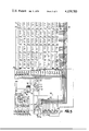
- FIG. 5 shows the complete wiring diagram
- the rotatable drum structure shown in FIGS. 1 to 3 consists of a vertical cylinder 1, which has a central axially extending aperture, and which is supported by a base plate 2; the drum structure is capable of being rotated by means of a geared electrical motor 3, the driven pinion 4 of which meshes with a gear wheel 5 integral with cylinder 1 just above the said base plate.
- An electromagnetic brake 33 which makes it possible to block the motor 3 when its supply is cut off is associated to the shaft of this motor.
- the cylinder 1 is formed by an assembly comprising a plurality of superposed rings, for example eight in number, such as rings 11, 12, 13, 14, 15, 16, 17 and 18 each having on its periphery a very large number, for example 60, of juxtaposed cells such as 20 11 , 20 12 . . 20 18 , 21 11 , 21 12 . . . 21 18 , etc., the cells bearing the same reference number as the reference index of the corresponding ring being disposed on the same generatrix of the cylinder.
- Disposed in each cell is a magazine consisting of a case 6 (FIG. 3), in the shape of an inverted U open at the back and at the bottom, and in which key blanks are stacked, a different model being stacked in each cell.
- each of the rings 11 to 18 there is a cam such as 22, each cam being capable of actuating the nose 23 of the movable contact of a limit switch 24 corresponding to a vertical row of cells.
- the switches 24 are mounted on a central fixed support disposed in the central aperture of the drum structure, each of these switches is operated by its associated cam in order instantly to stop the motor driving the drum 1 when, during rotation of the drum, the vertical row of cells containing the selected cell is brough in the diametral plane containing the ejector means which bring about ejection of the blank onto one of the plates forming inclined surfaces 25 11 , 25 12 , 25 13 . . . 25 18 directing the ejected blank to a receptacle 26 (FIG. 1).
- the cams and/or their associated limit switches are angularly shifted with respect to each other to be able to stop the drum structure with a selected vertical row of cells in front of the ejectors.
- the limit switches may be vertically aligned and the cams angularly shifted with respect to each other for an angle which corresponds to the angularly distance between two adjacent cells lying in a same horizontal plane. But a reverse arrangement may also be adopted.
- ejector means Mounted on the central fixed support disposed in the central aperture of the cylinder structure, there are ejector means, one per superposed levels or series of cells uniformly distributed around the axis of the drum, each comprising an electromagnet 27 (FIGS. 1 to 3) which is energized at the moment when the selected cell stops in the vertical plane in which all the ejector electromagnets are located, in front of the delivery plates 25.
- electromagnet 27 FIGS. 1 to 3
- Each of the electromagnets comprises a movable member 28 which is attracted when the electromagnet is energized and connected by a very short cable 29 to a return device mounted on the fixed support and comprising a small pulley 30 which this cable causes to turn and a larger pulley 31 on which is wound a longer cable 34 attached to a steel tongue 32 guided in a swallowtail slide and penetrating the cell which has stopped opposite the electromagnet in order to eject therefrom the blank 7 resting on the bottom of the cell and which is not retained by the rod 9 of the corresponding magazine 6.
- a return spring restores the tongue 32 to its initial position after ejection of the blank.
- the stroke of the tongue is longer than that of the armature of the electromagnet which makes it possible to reduce the bulk of the latter and at the same time to achieve a shorter operating time. It will be seen hereinafter that in order to obtain a very rapid operation of the ejector electromagnets which impart a very abrupt movement to the ejector tongue 32, the ejector electromagnet is energized by a brief high intensity pulse produced by the discharge of a previously charged capacitor.
- control panel As illustrated in the simplified diagram in FIG. 4, there is associated to the dispenser a control panel not shown but arranged as will be described with FIG. 5, which panel comprises a number of template members 35 corresponding to the number of cells per level of the structure drum, in other words 60 in the example chosen. Disposed in each plate 35 are slots equal in number to that of the stages of the drum, in other words eight in the example chosen, the slots 36, 36', 36" on each plate 35 having in cross-section a form corresponding respectively to that of the blanks contained in the eight cells which are in vertical alignment that is disposed along the same generatrix of the drum.
- the template members are made of an electrical conducting material, and introduction of the specimen key 40 into one of the slots has the effect of making an electrical connection between this plate and one of the terminals 37, 37', 37" . . . disposed behind the plate and respectively connected by eight horizontal conductors 38, 38', of which only three are shown in FIG. 4, to eight vertical conductors, 39, 39', 39" . . . of which only three are shown.
- the conductors 39, 39', 39" . . . are respectively connected to the windings of eight level or stage relays R 11, R 12, R 13 . . . which are mounted in parallel on the supply circuit.
- the supply circuit is thus closed by insertion of the specimen key 40 into the template and monitored furthermore by the limit switch 24, which is normally closed, on the ring 12 of the stage in which is contained the cell containing the blanks corresponding to the slot 36' into which the key 40 has been inserted.
- Mounted in the circuit which is thus monitored by the specimen key and the limit switch 24 is a push button switch 41 controlling operation of the motor via the winding of the relay R 19 mounted in series with the armatures r 11, r 12, r 13 . . .
- stage relays R11 to R18 Other armatures r'11, r'12, r'13 . . . of the stage relays are mounted respectively in series with the ejector electromagnets 27 11 , 27 12 . . . disposed in the corresponding stages 11 to 18.
- the dispenser according to the simplified diagram functions as follows:
- Insertion of the specimen key 40 into the slot 36' prepares the supply circuit of relay R12 of the corresponding level of cells, which circuit is completed by manually pushing push-button 41 in its operating position, thus causing energization of the motor 3 with the result that the drum 1 is rotated about its axis.
- the cam 22 associated to the ring 12 effects opening of the limit switch 34.
- the relay R12 is de-energized and its armature r12 opens and causes de-energizing of the relay 19 which cuts the supply to the motor so that the drum stops in the selected angular position the brake 33 blocking the rotor of motor 3.
- the armature r'12 closes the circuit of electromagnet 27 12 of the corresponding level or superposed series of cells and actuates the ejector so that a blank corresponding to the specimen key 40 is passed into the receptacle 26.
- FIG. 5 shows the complete wiring diagram of the dispenser comprising 60 templates 35 1 to 35 60 disposed, in order to reduce the overall height of the control panel, in six columns each containing templates and each plate, like the plate 35 in the diagram in FIG. 4, offering eight slots corresponding to eight vertically aligned cells of the superposed series of cells.
- the push-button 41 controlling the supply of motor 3 is disposed in an alternating current supply circuit of for example 220 volts.
- the supply circuit includes a transformer 42 having multiple tappings and a rectifier bridge 43 providing for example a direct current of 35 volts, while a rectifier bridge 44 is supplying a direct current of for example 24 volts to the magnetic brake 33 and to the various relays referred to hereinabove.
- the armature r19 of the relay 19 closes the circuit of the motor and, when it is de-energized, it closes the circuit of the brake 33 through its armature r'19 to stop the drum in the selected angular position.
- the keys of one and the same manufacturer have identical cross-sections so that they can therefore be introduced into a same slot of the template, but are of different lengths. Nevertheless, in order that the shorter keys may close the circuit of the relay R corresponding to the cell containing the corresponding blanks, while on the other hand the longer keys of the same cross-section cannot close the circuit of the relays corresponding to the shorter blanks, the key blanks of different lengths and of the same cross-section are distributed over cells situated on different levels.
- the templates 35 comprise as shown in FIG. 4, behind the slot 36' corresponding to the cross-section of keys of different lengths, supplementary terminals 37a'' and 37a'''.
- terminal 37' corresponds to the longest length of key and that the corresponding blanks are contained in a cell of the cell level controlled by relay R 14. Nevertheless, introduction of the specimen key at the same time completes the circuits of the terminals 37'' and 37''' which corresponds to cells situated in the stages or levels referenced 13 and 14.
- the relays R 13 and R 14 comprise supplementary armatures r'13 and r'14 mounted in series with the armature r 12 of the relay R 12 and which are mounted in such a way as to lock the circuit of the ejector 27 12 when the desired blank corresponds to the stage of the relay R 13 or R 14 and reciprocally a supplementary armature r"14 being mounted in series with the armature r13 of the ejector electromagnet 27 13 , so that only the armature r14 of the relay R 14 produces operation of the electro-ejector 27 14 .
- the dispenser likewise comprises a direct manual control which makes it possible to select the blanks corresponding to the most current specimen keys which the operator knows by heart.
- the operator instead of operating the drum by inserting the specimen key into one of the templates 35, the operator actuates one of the push button switches 48 1 , 48 2 , 48 3 , 48 3 . . . which via horizontal conductors 49, 49', 49" respectively connected to the vertical conductors 39', 39'', 39'''' . . . close the circuits of the stage relays R 11 to R 18 , these push buttons being moreover connected to a conductor 50 controlled by a supplementary armature r''' T 45 of the time delay relay RT 45.
- These push buttons 48 are associated with limit switches 51 connected to limit switches on the templates in which the blanks to be selected are located, so that the operation of the apparatus based on actuation of the push buttons 48 is the same as that which has been described above.
Landscapes
- Engineering & Computer Science (AREA)
- Mechanical Engineering (AREA)
- Sampling And Sample Adjustment (AREA)
- Hydraulic Motors (AREA)
- Push-Button Switches (AREA)
Applications Claiming Priority (2)
| Application Number | Priority Date | Filing Date | Title |
|---|---|---|---|
| FR7629616A FR2366099A1 (fr) | 1976-10-01 | 1976-10-01 | Distributeur-selecteur d'ebauches de cles plates |
| FR7629616 | 1976-10-01 |
Publications (1)
| Publication Number | Publication Date |
|---|---|
| US4159783A true US4159783A (en) | 1979-07-03 |
Family
ID=9178299
Family Applications (1)
| Application Number | Title | Priority Date | Filing Date |
|---|---|---|---|
| US05/835,172 Expired - Lifetime US4159783A (en) | 1976-10-01 | 1977-09-20 | Selector-dispenser of flat key blanks |
Country Status (6)
| Country | Link |
|---|---|
| US (1) | US4159783A (cg-RX-API-DMAC10.html) |
| JP (1) | JPS53111898A (cg-RX-API-DMAC10.html) |
| DE (1) | DE2741468C2 (cg-RX-API-DMAC10.html) |
| FR (1) | FR2366099A1 (cg-RX-API-DMAC10.html) |
| GB (1) | GB1539135A (cg-RX-API-DMAC10.html) |
| IT (1) | IT1081023B (cg-RX-API-DMAC10.html) |
Cited By (24)
| Publication number | Priority date | Publication date | Assignee | Title |
|---|---|---|---|---|
| US4661806A (en) * | 1985-05-10 | 1987-04-28 | Peters Gilbert A | Computer controlled key management system |
| US4996680A (en) * | 1988-06-03 | 1991-02-26 | Starr Development Company, S.A. | Automatic changing apparatus for a recording medium |
| US5004966A (en) * | 1989-11-29 | 1991-04-02 | Eakin Gary N | Computer activated reward dispensing machine |
| US5136562A (en) * | 1989-04-11 | 1992-08-04 | Staar Development, S.A. | Automatic changer for information storage devices |
| US5251782A (en) * | 1991-08-16 | 1993-10-12 | Creative Technology, Inc. | Object dispenser apparatus and method |
| US5713648A (en) * | 1995-11-17 | 1998-02-03 | Cvs H.C., Inc. | Apparatus for storing and dispensing medication |
| US5984509A (en) * | 1997-11-12 | 1999-11-16 | Hamilton Safe Company, Inc. | Cash and rotary rolled coin dispensing apparatus |
| US20040148988A1 (en) * | 2003-02-05 | 2004-08-05 | Taylor Mark Raymond | Lock key with head and blade |
| US20080084307A1 (en) * | 2006-02-15 | 2008-04-10 | Peter Johannes M | Electronic article surveillance marker |
| US20090255885A1 (en) * | 2005-10-20 | 2009-10-15 | Alba Scientific Services Limited | Apparatus for Laboratory Ware |
| US8992145B1 (en) | 2010-11-08 | 2015-03-31 | The Hillman Group, Inc. | Multi-key duplication, identification and cutting machine with clamp |
| US9073133B1 (en) | 2010-07-15 | 2015-07-07 | The Hillman Group, Inc. | Key blank and carrier adapted for positioning a key blank in a cutter during bit cutting |
| US9149877B1 (en) | 2010-07-15 | 2015-10-06 | The Hillman Group, Inc. | Interaction between a key duplication housing and a key blank carrier |
| US9468982B1 (en) | 2010-07-15 | 2016-10-18 | The Hillman Group, Inc. | Automated key duplication system and method |
| US9556649B1 (en) | 2010-07-15 | 2017-01-31 | The Hillman Group, Inc. | Key identification system |
| US9558236B1 (en) | 2010-07-15 | 2017-01-31 | The Hillman Group, Inc. | Master key identification and feedback system |
| US9586272B1 (en) | 2010-07-15 | 2017-03-07 | The Hillman Group, Inc. | Key blank and carrier adapted for positioning a key blank in a cutter during bit cutting |
| US10124420B2 (en) | 2016-02-08 | 2018-11-13 | The Hillman Group, Inc. | Key duplication machine having user-based functionality |
| US10196834B2 (en) | 2013-08-16 | 2019-02-05 | The Hillman Group, Inc. | Fabrication system for key making machine |
| US10406607B2 (en) | 2016-09-13 | 2019-09-10 | The Hillman Group, Inc. | Key duplication machine having pivoting clamp |
| US10503384B2 (en) * | 2002-08-02 | 2019-12-10 | Object Identification System | Object identification system |
| US10628813B2 (en) | 2010-06-03 | 2020-04-21 | The Hillman Group, Inc. | Key duplication system |
| US10737336B2 (en) | 2006-11-28 | 2020-08-11 | The Hillman Group, Inc. | Self service key duplicating machine with automatic key model identification system |
| US10737335B2 (en) | 2017-03-17 | 2020-08-11 | The Hillman Group, Inc. | Key duplication system with key blank orientation detection features |
Citations (1)
| Publication number | Priority date | Publication date | Assignee | Title |
|---|---|---|---|---|
| US3265245A (en) * | 1964-08-19 | 1966-08-09 | Keith L Harden | Key blank dispenser |
Family Cites Families (5)
| Publication number | Priority date | Publication date | Assignee | Title |
|---|---|---|---|---|
| US2244985A (en) * | 1937-10-30 | 1941-06-10 | Kearney & Trecker Corp | Machine tool |
| US3116665A (en) * | 1961-12-28 | 1964-01-07 | Osco Corp | Key duplicating machine |
| FR1347246A (fr) * | 1962-11-21 | 1963-12-27 | Appareil pour distribuer et découper des ébauches de clés | |
| US3358561A (en) * | 1965-10-21 | 1967-12-19 | Coin A Key Inc | Automatic pattern cutting and vending machine |
| US3796130A (en) * | 1972-02-10 | 1974-03-12 | Sargent & Greenleaf | Key duplicating and vending machine |
-
1976
- 1976-10-01 FR FR7629616A patent/FR2366099A1/fr active Granted
-
1977
- 1977-07-05 GB GB28027/77A patent/GB1539135A/en not_active Expired
- 1977-07-13 IT IT12686/77A patent/IT1081023B/it active
- 1977-09-15 DE DE2741468A patent/DE2741468C2/de not_active Expired
- 1977-09-20 US US05/835,172 patent/US4159783A/en not_active Expired - Lifetime
- 1977-09-30 JP JP11777577A patent/JPS53111898A/ja active Pending
Patent Citations (1)
| Publication number | Priority date | Publication date | Assignee | Title |
|---|---|---|---|---|
| US3265245A (en) * | 1964-08-19 | 1966-08-09 | Keith L Harden | Key blank dispenser |
Cited By (46)
| Publication number | Priority date | Publication date | Assignee | Title |
|---|---|---|---|---|
| US4661806A (en) * | 1985-05-10 | 1987-04-28 | Peters Gilbert A | Computer controlled key management system |
| US4996680A (en) * | 1988-06-03 | 1991-02-26 | Starr Development Company, S.A. | Automatic changing apparatus for a recording medium |
| US5136562A (en) * | 1989-04-11 | 1992-08-04 | Staar Development, S.A. | Automatic changer for information storage devices |
| US5004966A (en) * | 1989-11-29 | 1991-04-02 | Eakin Gary N | Computer activated reward dispensing machine |
| US5251782A (en) * | 1991-08-16 | 1993-10-12 | Creative Technology, Inc. | Object dispenser apparatus and method |
| US5713648A (en) * | 1995-11-17 | 1998-02-03 | Cvs H.C., Inc. | Apparatus for storing and dispensing medication |
| US6202006B1 (en) | 1997-11-12 | 2001-03-13 | Hamilton Safe Company, Inc. | Cassette for a rotary rolled coin dispenser |
| US6019247A (en) * | 1997-11-12 | 2000-02-01 | Hamilton Safe Company, Inc. | Rotary rolled coin dispenser |
| US5984509A (en) * | 1997-11-12 | 1999-11-16 | Hamilton Safe Company, Inc. | Cash and rotary rolled coin dispensing apparatus |
| US11334234B2 (en) | 2002-08-02 | 2022-05-17 | Hy-Ko Products Company Llc | Object identification system |
| US10503384B2 (en) * | 2002-08-02 | 2019-12-10 | Object Identification System | Object identification system |
| US20040148988A1 (en) * | 2003-02-05 | 2004-08-05 | Taylor Mark Raymond | Lock key with head and blade |
| US20090255885A1 (en) * | 2005-10-20 | 2009-10-15 | Alba Scientific Services Limited | Apparatus for Laboratory Ware |
| US8196759B2 (en) * | 2005-10-20 | 2012-06-12 | Alba Scientific Services, Ltd | Apparatus for laboratory ware |
| US20080084307A1 (en) * | 2006-02-15 | 2008-04-10 | Peter Johannes M | Electronic article surveillance marker |
| US10737336B2 (en) | 2006-11-28 | 2020-08-11 | The Hillman Group, Inc. | Self service key duplicating machine with automatic key model identification system |
| US11810090B2 (en) | 2010-06-03 | 2023-11-07 | The Hillman Group, Inc. | Key duplication system |
| US11170356B2 (en) | 2010-06-03 | 2021-11-09 | The Hillman Group, Inc. | Key duplication system |
| US10628813B2 (en) | 2010-06-03 | 2020-04-21 | The Hillman Group, Inc. | Key duplication system |
| US10007979B2 (en) | 2010-07-15 | 2018-06-26 | The Hillman Group, Inc. | Key identification system |
| US9556649B1 (en) | 2010-07-15 | 2017-01-31 | The Hillman Group, Inc. | Key identification system |
| US9895752B2 (en) | 2010-07-15 | 2018-02-20 | The Hillman Group, Inc. | Automated key duplication system and method |
| US9586272B1 (en) | 2010-07-15 | 2017-03-07 | The Hillman Group, Inc. | Key blank and carrier adapted for positioning a key blank in a cutter during bit cutting |
| US10010949B2 (en) | 2010-07-15 | 2018-07-03 | The Hillman Group, Inc. | Master key identification and feedback system |
| US9073133B1 (en) | 2010-07-15 | 2015-07-07 | The Hillman Group, Inc. | Key blank and carrier adapted for positioning a key blank in a cutter during bit cutting |
| US9764393B2 (en) | 2010-07-15 | 2017-09-19 | The Hillman Group, Inc. | Key blank and carrier adapted for positioning a key blank in a cutter during bit cutting |
| US9149877B1 (en) | 2010-07-15 | 2015-10-06 | The Hillman Group, Inc. | Interaction between a key duplication housing and a key blank carrier |
| US10846842B2 (en) | 2010-07-15 | 2020-11-24 | The Hillman Group, Inc. | Key identification system |
| US9558236B1 (en) | 2010-07-15 | 2017-01-31 | The Hillman Group, Inc. | Master key identification and feedback system |
| US9468982B1 (en) | 2010-07-15 | 2016-10-18 | The Hillman Group, Inc. | Automated key duplication system and method |
| US8992145B1 (en) | 2010-11-08 | 2015-03-31 | The Hillman Group, Inc. | Multi-key duplication, identification and cutting machine with clamp |
| US10301844B2 (en) | 2013-08-16 | 2019-05-28 | The Hillman Group, Inc. | Identification module for key making machine |
| US11642744B2 (en) | 2013-08-16 | 2023-05-09 | The Hillman Group, Inc. | Identification module for key making machine |
| US11391062B2 (en) | 2013-08-16 | 2022-07-19 | The Hillman Group, Inc. | Fabrication system for key making machine |
| US10577830B2 (en) | 2013-08-16 | 2020-03-03 | The Hillman Group, Inc. | Identification module for key making machine |
| US10196834B2 (en) | 2013-08-16 | 2019-02-05 | The Hillman Group, Inc. | Fabrication system for key making machine |
| US10400474B1 (en) | 2013-08-16 | 2019-09-03 | The Hillman Group, Inc. | Identification module for key making machine |
| US10940549B2 (en) | 2016-02-08 | 2021-03-09 | The Hillman Group, Inc. | Key duplication machine having user-based functionality |
| US10668543B2 (en) | 2016-02-08 | 2020-06-02 | The Hillman Group, Inc. | Key duplication machine having user-based functionality |
| US11780017B2 (en) | 2016-02-08 | 2023-10-10 | The Hillman Group, Inc. | Key duplication machine having user-based functionality |
| US10124420B2 (en) | 2016-02-08 | 2018-11-13 | The Hillman Group, Inc. | Key duplication machine having user-based functionality |
| US10406607B2 (en) | 2016-09-13 | 2019-09-10 | The Hillman Group, Inc. | Key duplication machine having pivoting clamp |
| US10661359B2 (en) | 2016-09-13 | 2020-05-26 | The Hillman Group, Inc. | Key duplication machine having pivoting clamp |
| US11697165B2 (en) | 2016-09-13 | 2023-07-11 | The Hillman Group, Inc. | Key duplication machine having pivoting clamp |
| US10737335B2 (en) | 2017-03-17 | 2020-08-11 | The Hillman Group, Inc. | Key duplication system with key blank orientation detection features |
| US12128486B2 (en) | 2017-03-17 | 2024-10-29 | The Hillman Group, Inc. | Key duplication system with key blank orientation detection features |
Also Published As
| Publication number | Publication date |
|---|---|
| FR2366099A1 (fr) | 1978-04-28 |
| DE2741468C2 (de) | 1982-08-12 |
| FR2366099B1 (cg-RX-API-DMAC10.html) | 1980-12-05 |
| GB1539135A (en) | 1979-01-24 |
| DE2741468A1 (de) | 1978-04-06 |
| JPS53111898A (en) | 1978-09-29 |
| IT1081023B (it) | 1985-05-16 |
Similar Documents
| Publication | Publication Date | Title |
|---|---|---|
| US4159783A (en) | Selector-dispenser of flat key blanks | |
| US3294281A (en) | Package vendor with helix shaped delivery spindle | |
| US3116665A (en) | Key duplicating machine | |
| US3772757A (en) | Machine for automatically attaching hinges to doors and jambs | |
| US4303179A (en) | High density can stack for automatic can venders | |
| US2638396A (en) | Sandwich vending machine | |
| US4190066A (en) | Coin and paper money payout system | |
| US4236649A (en) | Compact vending machine | |
| US2342652A (en) | Multiselective phonograph | |
| US2572609A (en) | Automatic phonograph | |
| US3349881A (en) | Vending cycle lockout circuit | |
| GB2032403A (en) | Automatic coin dispenser | |
| GB1000604A (en) | Article dispensing machine | |
| US4746209A (en) | Device for storing and handling slides | |
| US3048181A (en) | Control for coin dispensing apparatus | |
| US3158246A (en) | Vending machine | |
| US2550884A (en) | Motor-operated article dispensing machine | |
| GB2209331A (en) | Vending machine for hot food | |
| US1787644A (en) | Phonographic attachment for merchandise-dispensing apparatus | |
| US3972338A (en) | Coin changer with dual-slide payout mechanism | |
| US3486601A (en) | Vending cycle lockout circuit | |
| US2170288A (en) | Coin feeding apparatus | |
| US2204853A (en) | Coin or token handling apparatus | |
| US4407430A (en) | Apparatus for delivering merchandise from a vending machine | |
| US2848003A (en) | Change-making mechanism |