US415744A - Rumbling-machine - Google Patents
Rumbling-machine Download PDFInfo
- Publication number
- US415744A US415744A US415744DA US415744A US 415744 A US415744 A US 415744A US 415744D A US415744D A US 415744DA US 415744 A US415744 A US 415744A
- Authority
- US
- United States
- Prior art keywords
- plate
- rumbling
- door
- machine
- rumbler
- Prior art date
- Legal status (The legal status is an assumption and is not a legal conclusion. Google has not performed a legal analysis and makes no representation as to the accuracy of the status listed.)
- Expired - Lifetime
Links
- 210000000282 Nails Anatomy 0.000 description 6
- XEEYBQQBJWHFJM-UHFFFAOYSA-N iron Chemical compound [Fe] XEEYBQQBJWHFJM-UHFFFAOYSA-N 0.000 description 4
- 239000000463 material Substances 0.000 description 4
- 238000010276 construction Methods 0.000 description 2
- 239000004519 grease Substances 0.000 description 2
- 229910052742 iron Inorganic materials 0.000 description 2
- 238000000034 method Methods 0.000 description 2
- 238000005096 rolling process Methods 0.000 description 2
Images
Classifications
-
- B—PERFORMING OPERATIONS; TRANSPORTING
- B24—GRINDING; POLISHING
- B24B—MACHINES, DEVICES, OR PROCESSES FOR GRINDING OR POLISHING; DRESSING OR CONDITIONING OF ABRADING SURFACES; FEEDING OF GRINDING, POLISHING, OR LAPPING AGENTS
- B24B31/00—Machines or devices designed for polishing or abrading surfaces on work by means of tumbling apparatus or other apparatus in which the work and/or the abrasive material is loose; Accessories therefor
- B24B31/02—Machines or devices designed for polishing or abrading surfaces on work by means of tumbling apparatus or other apparatus in which the work and/or the abrasive material is loose; Accessories therefor involving rotary barrels
Definitions
- the object of my invention is to simplify these operations.
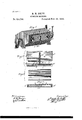
- Figure l is a perspective view.
- Fig. 2 is a detail of the door.
- Fig. 3 is a detail of the plate.
- Fig. 4 is a detail showing operation.
- I use'a rumblerA which maybe of any form or material, as preferred.
- the opening for charging the rumbler is made of good size to facilitate the filling and emptying of the same.
- the door 13 is made of two plates of iron.
- the inner plate or B is pierced with holes, countersunk, as shown, and is secured by the bolsters and rivets B at a little distance from the plate B
- This arrangement permits the small chips and sawdust to rattle out, passing through Band between that and B but prevents anything of much length from getting out through B.
- a plate O is provided that j nst fills the space between B and B. This plate 0, during the process of rumbling, is kept in place by the stop-pins B and spring 13*.
- the door B when in place is secured to the runr bler by means of the screw-clamps A, so that it may be securely held, but easily removed and replaced, as shown. W'hen the nails have been rolled a proper time, the spring-catch B is lifted,the plate 0 removed,and the rolling continued for a short ti1ne,rattlin g the sawdust and small chips out and permitting the nails to roll against each other. Then the clamps A are slackened, the door B opened and the charge replaced by another, the door closed and the plate O returned to its place, and the machine started again Without loss of time.
- the door B consisting of the perforated sieve B and outer plate B in combination with the rumbler A, as herein shown and described.
- the door B consisting of the sieve B and the outer plate B .as de scribed, combined with the removable plate 0, as and for the purposes herein shown and set forth.
Description
(No Model.)
- M. M. SMITH.
RUMBLING MACHINE.
No. 415,744. Patented Nov. 26, 1889..
I uw'uu llllllllillllllllllll"HullllllmmmflgMn Im uuni iq gba i i -gmunmmuuuumm "ll" UNITED STATES PATENT OFFICE.
MINARD M. SMITH, OF BROOKLYN, NE YORK.
RUMBL ING-MACHINE.
SPECIFIGATIQN forming part of Letters Patent No. 415,744, dated November 26, 1889.
' Application filed June 30, 1888- Serial No. 278,710. (No model.)
. New York, have invented certain new and use ful Improvements in Rumbling-Machines, of which the following is a specification.
\Vire nails and similar things are rumbled or rolled in sawdust to remove the grease or oil and sift out the fag-ends and bits of wire or other matter.
The object of my invention is to simplify these operations.
In the accompanying drawings, Figure l is a perspective view. Fig. 2 is a detail of the door. Fig. 3 is a detail of the plate. Fig. 4 is a detail showing operation.
I use'a rumblerA,which maybe of any form or material, as preferred. The opening for charging the rumbler is made of good size to facilitate the filling and emptying of the same. The door 13 is made of two plates of iron. The inner plate or B is pierced with holes, countersunk, as shown, and is secured by the bolsters and rivets B at a little distance from the plate B This arrangement permits the small chips and sawdust to rattle out, passing through Band between that and B but prevents anything of much length from getting out through B. A plate O is provided that j nst fills the space between B and B. This plate 0, during the process of rumbling, is kept in place by the stop-pins B and spring 13*. The door B when in place is secured to the runr bler by means of the screw-clamps A, so that it may be securely held, but easily removed and replaced, as shown. W'hen the nails have been rolled a proper time, the spring-catch B is lifted,the plate 0 removed,and the rolling continued for a short ti1ne,rattlin g the sawdust and small chips out and permitting the nails to roll against each other. Then the clamps A are slackened, the door B opened and the charge replaced by another, the door closed and the plate O returned to its place, and the machine started again Without loss of time.
It is obvious that any suitable material may be used in the construction or operation of this mechanism; also, the door B might be hinged or screwed to the rumbler, or made to slip in grooves, if preferred. Nor is the form, number, orarrangement of the stop-pins B or spring-catch 13 essential, as screws or bolts might be substituted therefor. I
That I claim, and desire to secure by Letters Patent, is
1. In a rumbler, the door B, consisting of the perforated sieve B and outer plate B in combination with the rumbler A, as herein shown and described.
2. In a rumbler, the door B, consisting of the sieve B and the outer plate B .as de scribed, combined with the removable plate 0, as and for the purposes herein shown and set forth.
Signed at New York,in the county of New York and State of New York, this 28th day of June, A. D. 1888.
MINARD M. SMITH.
Vitnesses:
BENJ. T. PETTY, A. VIvAETrAs.
Publications (1)
| Publication Number | Publication Date |
|---|---|
| US415744A true US415744A (en) | 1889-11-26 |
Family
ID=2484673
Family Applications (1)
| Application Number | Title | Priority Date | Filing Date |
|---|---|---|---|
| US415744D Expired - Lifetime US415744A (en) | Rumbling-machine |
Country Status (1)
| Country | Link |
|---|---|
| US (1) | US415744A (en) |
Cited By (1)
| Publication number | Priority date | Publication date | Assignee | Title |
|---|---|---|---|---|
| USD757136S1 (en) * | 2015-02-09 | 2016-05-24 | Soma International Ltd. | Rock tumbler |
-
0
- US US415744D patent/US415744A/en not_active Expired - Lifetime
Cited By (1)
| Publication number | Priority date | Publication date | Assignee | Title |
|---|---|---|---|---|
| USD757136S1 (en) * | 2015-02-09 | 2016-05-24 | Soma International Ltd. | Rock tumbler |
Similar Documents
| Publication | Publication Date | Title |
|---|---|---|
| US1243115A (en) | Door-fastening means. | |
| US2301444A (en) | Door fastener | |
| US415744A (en) | Rumbling-machine | |
| US792183A (en) | Traveling-bag. | |
| US652778A (en) | Tool-box. | |
| US1883646A (en) | Door for cylindrical receptacles | |
| US896529A (en) | Traveling-case. | |
| US1064448A (en) | Dump-wagon. | |
| US1000807A (en) | Grain-door for cars. | |
| US821167A (en) | Kitchen-cabinet. | |
| US964245A (en) | Hopper for grain-drills. | |
| US241347A (en) | Meal-chest | |
| US1409635A (en) | Fastener for mine-car doors | |
| US255889A (en) | Ash-sifter | |
| US170362A (en) | Improvement in washing-machines | |
| US439901A (en) | yon seekey | |
| US691802A (en) | Tumbling-box. | |
| US1069111A (en) | Grain-door for box-cars. | |
| US552256A (en) | Trunk | |
| US762685A (en) | Trunk-catch. | |
| US955674A (en) | Device for preventing doors from sagging. | |
| US953869A (en) | Grain-door. | |
| US336217A (en) | Churn | |
| US1193601A (en) | Freight-car door | |
| US207969A (en) | Improvement in express-boxes |