US415196A - Bob-sleigh - Google Patents
Bob-sleigh Download PDFInfo
- Publication number
- US415196A US415196A US415196DA US415196A US 415196 A US415196 A US 415196A US 415196D A US415196D A US 415196DA US 415196 A US415196 A US 415196A
- Authority
- US
- United States
- Prior art keywords
- reach
- bob
- strip
- runners
- bolster
- Prior art date
- Legal status (The legal status is an assumption and is not a legal conclusion. Google has not performed a legal analysis and makes no representation as to the accuracy of the status listed.)
- Expired - Lifetime
Links
- 210000003127 knee Anatomy 0.000 description 5
- 238000010276 construction Methods 0.000 description 3
- 230000000717 retained effect Effects 0.000 description 3
- 239000002184 metal Substances 0.000 description 2
- 230000006978 adaptation Effects 0.000 description 1
- 239000000463 material Substances 0.000 description 1
Images
Classifications
-
- B—PERFORMING OPERATIONS; TRANSPORTING
- B62—LAND VEHICLES FOR TRAVELLING OTHERWISE THAN ON RAILS
- B62B—HAND-PROPELLED VEHICLES, e.g. HAND CARTS OR PERAMBULATORS; SLEDGES
- B62B13/00—Sledges with runners
- B62B13/02—Sledges with runners characterised by arrangement of runners
- B62B13/06—Sledges with runners characterised by arrangement of runners arranged in two or more parallel lines
Definitions
- Each of the runners B is made, preferably, of a single piece, the same being cutaway in such a manner as to give the desired curvature for the runner and leaving the raised portion B, which serves as aknee, over the top of which knee is secured a metallic plate B upon which plate is designed to restthe end of the transverse timber O, which timberis retained in place by means of the bolts C, which are passed downward through the metallic bra cestrip 0 and after passing through said crosstimber extend a short distance into the knee.
- the bolts C are designed to be fastened into the brace-strip C by entering the bracestrip from the under side and being headed down 011 top.
- the brace-strip C is made of spring metal, and is passed over the end of the transverse timber, and has its ends secured to the upper face or edge of the runner by means of the bolts D, passed through the elongated slots 0 in the brace-strip, said bolt being passed upwardly from the lower face of the runner, the lower end of the bolt being provided with an enlarged head D, which is countersunk in the lower face of the runner, and the bolt is retained in place by the shoe D
- the upper end of the bolt D is screw-threaded to receive a nut D
- the vertical bolts or rods 0' being retained loosely within the holes in the knee, may be readily lifted out when the brace-strip is removed, which may be done at any time by simply removing the nuts D Any one of the runners may thus be quickly and easily detached from the vehicle when it may be found desirable or necessary to remove the same for the purpose of repair or other purpose.
- the metallic strips E which strips are bent back over the ends of the roll, and their free ends are bent to form the loops E adapted to engage the corresponding hooks E upon the inner faces of the forward ends of the runners.
- These hooks are secured to the runners in such positions as to permit the loops to be hooked over the same only when the roll is turned into such a position as to throw the reach which is attached thereto into a substantially vertical position, so that the parts cannot be detached until the front end of the reach has been detached from its connection with the forward bob. This dispenses with the roller rod and braces commonly used.
- the roll F, to which the neap or pole F is secured, is attached to the forward bob in the manner described for securing the roll to the rear bob, thus dispensing with the use of the roller rod and braces commonlyused.
- the reach G is made of a heavy strip of sheet metal, the rear end of the reach being secured to the upper face of the roll and block by means of bolts G, as shown, a series of holes g being provided in the reach, so that the same may be adjusted readily in length.
- the forward bob is similar in all respects to the rear bob above described.
- the bolster H Near the forward end of the reach there is supported the bolster H, provided at its ends with grooves for the passage of chains, as is common in this class of sleds.
- This bolster is adjustable lengthwise of the reach by means ofa plurality of holes h to receive the kingbolt.
- the king-bolt I has its head countersunk in the lower side of the transverse timber and covered by a plate h, the king-bolt passing upward through the timber, through a wearing-plate 72 secured to the top of the said timber, through a plate J, attached to the under side of the bolster and serving as a guide for the reach, through one of the holes in the reach, and through the bolster, its upper end being screw-threaded and provided with a nut 72/ seated in a cavity in the top of the bolster, the said nut' and cavity being covered by a wearing-plate L.
- the rear bolster is connected with the transverse timber of the rear bob in the same manner.
- the forward end of the reach extends beyond the forward bolster and is provided with a seat M, attached thereto in any suitable manner.
- This provides a springy support for the seat, and serves to do away with much of the j olting occasioned by going over rough roads.
- transverse timbers of the rear and front bobs are provided with the metallic braces or an gle-irons N, which are attached to the under side of said timbers, and, with their vertical portions bearing against the knees of the runners, serve to brace the parts and prevent the runners from tilting out of a perpendicular position.
- the carrying of the seat on the forwardlyextended end of the reach places the seat in such a position that it is at all times out of the way of the load, so that in turning there is no danger of the driver being injured by the load.
Landscapes
- Engineering & Computer Science (AREA)
- Chemical & Material Sciences (AREA)
- Combustion & Propulsion (AREA)
- Transportation (AREA)
- Mechanical Engineering (AREA)
- Chemical And Physical Treatments For Wood And The Like (AREA)
Description
UNITED STATES PATENT OFFICE.
JOHN GREEN, OF ELHIRA, MICHIGAN.
BOB-SLEIGH.
SPECIFICATION forming part of Letters Patent No. 415,196, dated November 19, 1889.
Application fil dAugnst 31, 1889. Serial No. 322,552. (No model.)
T 0 all whom it may concern:
Be it known that 1, JOHN GREEN, a citizen of the United States, residing at Elmira, in the county of Otsego and State of Michigan, have invented certain new and useful lirprovements in BobSleighs; and I do declare the following to be a full, clear, and exact description of the invention, such as will enable others skilled in the art to which it appertains to make and use the same, reference being had to the accompanying drawings, and to the letters and figures of reference marked thereon, which form a part of this specification This invention relates to certain new and useful improvements in that class of bobsleds which are intended especially for use in moving lumber and heavy logs and timber; and it has for its object to generally improve upon the construction, as well as to cheapen, simplify, and render more efficient in operation this class of vehicles.
To these ends and to such others as the invention may pertain the same consists in the peculiar construction and in the novel combination, arrangement, and adaptation of parts, all as more fully hereinafter described, and specifically defined in the appended claims.
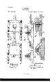
The invention is clearly illustrated in the accompanying drawings, which, with the letters of reference marked thereon, form a part of this specification, like letters of reference indicating like parts throughout the several views, and in which drawings Figure 1 is a top plan view of the same. Fig. 2 is a central vertical section. Figs. 3 and 4c are details more particularly hereinafter referred to.
Reference now being had to the details of the drawings by letter, A and A represent the forward and rearbobs, respectively. Each of the runners B is made, preferably, of a single piece, the same being cutaway in such a manner as to give the desired curvature for the runner and leaving the raised portion B, which serves as aknee, over the top of which knee is secured a metallic plate B upon which plate is designed to restthe end of the transverse timber O, which timberis retained in place by means of the bolts C, which are passed downward through the metallic bra cestrip 0 and after passing through said crosstimber extend a short distance into the knee. The bolts C are designed to be fastened into the brace-strip C by entering the bracestrip from the under side and being headed down 011 top. The brace-strip C is made of spring metal, and is passed over the end of the transverse timber, and has its ends secured to the upper face or edge of the runner by means of the bolts D, passed through the elongated slots 0 in the brace-strip, said bolt being passed upwardly from the lower face of the runner, the lower end of the bolt being provided with an enlarged head D, which is countersunk in the lower face of the runner, and the bolt is retained in place by the shoe D The upper end of the bolt D is screw-threaded to receive a nut D By this construction it will be readily seen that the brace-strip will serve to securely retain the parts in place, and at the same time it is adapted to give slightly without breaking upon occasions of sudden strain or jolt.
The vertical bolts or rods 0', being retained loosely within the holes in the knee, may be readily lifted out when the brace-strip is removed, which may be done at any time by simply removing the nuts D Any one of the runners may thus be quickly and easily detached from the vehicle when it may be found desirable or necessary to remove the same for the purpose of repair or other purpose.
To the front edge of the roll E of the rear bob are secured the metallic strips E, which strips are bent back over the ends of the roll, and their free ends are bent to form the loops E adapted to engage the corresponding hooks E upon the inner faces of the forward ends of the runners. These hooks are secured to the runners in such positions as to permit the loops to be hooked over the same only when the roll is turned into such a position as to throw the reach which is attached thereto into a substantially vertical position, so that the parts cannot be detached until the front end of the reach has been detached from its connection with the forward bob. This dispenses with the roller rod and braces commonly used.
The roll F, to which the neap or pole F is secured,is attached to the forward bob in the manner described for securing the roll to the rear bob, thus dispensing with the use of the roller rod and braces commonlyused.
Upon the front edge of the roll E is secured the block E by means of the metallic strip E the rear ends of which strip are passed through the said roll and are secured in place .by means of nuts, as shown, the body of the strip being passed around the outer edge of the block.
The reach G is made of a heavy strip of sheet metal, the rear end of the reach being secured to the upper face of the roll and block by means of bolts G, as shown, a series of holes g being provided in the reach, so that the same may be adjusted readily in length.
The forward bob is similar in all respects to the rear bob above described.
Near the forward end of the reach there is supported the bolster H, provided at its ends with grooves for the passage of chains, as is common in this class of sleds. This bolster is adjustable lengthwise of the reach by means ofa plurality of holes h to receive the kingbolt. The king-bolt I has its head countersunk in the lower side of the transverse timber and covered by a plate h, the king-bolt passing upward through the timber, through a wearing-plate 72 secured to the top of the said timber, through a plate J, attached to the under side of the bolster and serving as a guide for the reach, through one of the holes in the reach, and through the bolster, its upper end being screw-threaded and provided with a nut 72/ seated in a cavity in the top of the bolster, the said nut' and cavity being covered by a wearing-plate L. The rear bolster is connected with the transverse timber of the rear bob in the same manner.
The forward end of the reach extends beyond the forward bolster and is provided with a seat M, attached thereto in any suitable manner. This provides a springy support for the seat, and serves to do away with much of the j olting occasioned by going over rough roads.
The transverse timbers of the rear and front bobs are provided with the metallic braces or an gle-irons N, which are attached to the under side of said timbers, and, with their vertical portions bearing against the knees of the runners, serve to brace the parts and prevent the runners from tilting out of a perpendicular position.
The carrying of the seat on the forwardlyextended end of the reach places the seat in such a position that it is at all times out of the way of the load, so that in turning there is no danger of the driver being injured by the load.
hat I claim as new is 1. In a bob-sled, a reach extended beyond the front bolster and carrying the seat, substantially as described.
2. The combination, with the reach and bolster adjustable on said reach, of a' seat carried by the forward-extended end of the reach, substantially as described.
The combination,with the rear and front bobs, of the reach attached at its rear end to the rear bob, the said reach being formed of springy material, with its forward end extended beyond the front bolster, the front bolster, and the seat attached to the forwardextendedend of the reach, substantially as described.
4. The combination, with the runner and the transverse timber and the metallic plate B of the brace-strip passed over the timber and having its ends detachably connected to the runner, substantially as described.
5. The combination, With the runners and the metallic plate thereon, of the brace-strip passed over the'metallic plate and provided at its ends with elongated slots through which pass the bolts to secure it to the runners,
substantially as and for the purpose specifled.
6. The combination of the runners and the transverse timber thereon, the metallic plate B the spring bracestrip passed over the end of the transverse timber and the metallic plate, with its ends formed with elongated slots, the bolts passed through said slots and the runner, and the vertical bolts passed through the brace-strip and metallic plate and loosely through the transverse timber and into the knee of therunner, substantially as and for the purpose specified.
'7. The combination of the runners and a roll having metallic strips secured to its front edge, the outer ends of which strips are bent backward over the ends of the rolls and form loops adapted to engage corresponding hooks on the forward ends of the runners, substantially as and for the purpose specitied.
8. The combination, with the roll and JOHN GREEN.
Witnesses:
HIRAM T. CooK, ALBA E. GREEN.
Publications (1)
| Publication Number | Publication Date |
|---|---|
| US415196A true US415196A (en) | 1889-11-19 |
Family
ID=2484125
Family Applications (1)
| Application Number | Title | Priority Date | Filing Date |
|---|---|---|---|
| US415196D Expired - Lifetime US415196A (en) | Bob-sleigh |
Country Status (1)
| Country | Link |
|---|---|
| US (1) | US415196A (en) |
-
0
- US US415196D patent/US415196A/en not_active Expired - Lifetime
Similar Documents
| Publication | Publication Date | Title |
|---|---|---|
| US415196A (en) | Bob-sleigh | |
| US1108160A (en) | Non-skid metal sleigh-runner. | |
| US531937A (en) | Stone-boat | |
| US390632A (en) | Haven | |
| US329145A (en) | William a | |
| US1307841A (en) | Hay-rack bed-piece | |
| US443902A (en) | Farm-wagon | |
| US295154A (en) | Three-wheeled vehicle | |
| US613102A (en) | Sled attachment | |
| US93163A (en) | Improvement in head-blocks tor carriages | |
| US426450A (en) | George l | |
| US512686A (en) | Sulky | |
| US362242A (en) | Island | |
| US572059A (en) | Combined child s carriage and sled | |
| US1289519A (en) | Hay-rack. | |
| US387524A (en) | Snow-plow | |
| US668985A (en) | Wagon. | |
| US69497A (en) | skinner | |
| US538435A (en) | Wagon | |
| US1269255A (en) | Sled-runner for automobiles. | |
| US410211A (en) | Wagon-spring | |
| US429651A (en) | Thirds to jesse m | |
| US555580A (en) | Sleigh-runner | |
| US595851A (en) | Worth | |
| US393493A (en) | Samuel wheblee |