US4140951A - Mining machine - Google Patents
Mining machine Download PDFInfo
- Publication number
- US4140951A US4140951A US05/833,671 US83367177A US4140951A US 4140951 A US4140951 A US 4140951A US 83367177 A US83367177 A US 83367177A US 4140951 A US4140951 A US 4140951A
- Authority
- US
- United States
- Prior art keywords
- mining machine
- machine according
- branch
- motor
- drive unit
- Prior art date
- Legal status (The legal status is an assumption and is not a legal conclusion. Google has not performed a legal analysis and makes no representation as to the accuracy of the status listed.)
- Expired - Lifetime
Links
- 238000005065 mining Methods 0.000 title claims abstract description 28
- 238000004804 winding Methods 0.000 claims abstract description 17
- 230000006698 induction Effects 0.000 claims abstract description 9
- 238000012544 monitoring process Methods 0.000 claims 1
- 239000003990 capacitor Substances 0.000 description 4
- 239000003245 coal Substances 0.000 description 2
- 239000000428 dust Substances 0.000 description 2
- 230000007613 environmental effect Effects 0.000 description 2
- 230000004048 modification Effects 0.000 description 2
- 238000012986 modification Methods 0.000 description 2
- 238000001816 cooling Methods 0.000 description 1
- 230000000694 effects Effects 0.000 description 1
- 239000012530 fluid Substances 0.000 description 1
- 238000012423 maintenance Methods 0.000 description 1
- 239000000463 material Substances 0.000 description 1
Images


Classifications
-
- H—ELECTRICITY
- H02—GENERATION; CONVERSION OR DISTRIBUTION OF ELECTRIC POWER
- H02P—CONTROL OR REGULATION OF ELECTRIC MOTORS, ELECTRIC GENERATORS OR DYNAMO-ELECTRIC CONVERTERS; CONTROLLING TRANSFORMERS, REACTORS OR CHOKE COILS
- H02P25/00—Arrangements or methods for the control of AC motors characterised by the kind of AC motor or by structural details
- H02P25/16—Arrangements or methods for the control of AC motors characterised by the kind of AC motor or by structural details characterised by the circuit arrangement or by the kind of wiring
- H02P25/24—Variable impedance in stator or rotor circuit
- H02P25/26—Variable impedance in stator or rotor circuit with arrangements for controlling secondary impedance
-
- E—FIXED CONSTRUCTIONS
- E21—EARTH OR ROCK DRILLING; MINING
- E21C—MINING OR QUARRYING
- E21C29/00—Propulsion of machines for slitting or completely freeing the mineral from the seam
-
- E—FIXED CONSTRUCTIONS
- E21—EARTH OR ROCK DRILLING; MINING
- E21C—MINING OR QUARRYING
- E21C31/00—Driving means incorporated in machines for slitting or completely freeing the mineral from the seam
- E21C31/02—Driving means incorporated in machines for slitting or completely freeing the mineral from the seam for cutting or breaking-down devices
Definitions
- This invention relates to a mining machine.
- a fluid operated driving mechanism which usually comprises a hydraulic pump and a hydraulic motor.
- the pump and motor are employed so that an infinitely variable speed output can be obtained and hence the feed rate from the pump to the motor adjusted to suit changes in the hardness of the material which is being cut by the mining machine.
- the rotary cutter(s) of the mining machine can be driven by such a hydraulic drive.
- hydraulic drives in use underground present difficulties as regards the risk of environmental dust at the coal face entering the hydraulic system, thereby increasing the need for maintenance.
- a mining machine including:
- Drive unit means arranged to drive a haulage winch of the machine and a cutting tool of the machine, the drive unit means comprising a multi-phase induction motor with a wound rotor,
- Polyphase rectifier means arranged to receive the phase outputs of the motor and to combine these phase outputs to form a single unidirectional voltage output
- At least one branch connected to be supplied by the rectifier means, and
- the motor speed over the full range of operating torques can be varied over the higher speed ranges up to maximum speed as well as over the lower speed ranges through which the motor passes transiently on starting up.
- the effective impedance presented to the rotor windings may be varied in discrete or infinitesimal steps.
- the effective impedance varying means comprises a feedback loop including control means arranged to control the effective impedance presented by the said circuit to the rotor windings in accordance with a predetermined criterion set in the control means.
- control means arranged to control the effective impedance presented by the said circuit to the rotor windings in accordance with a predetermined criterion set in the control means.
- the effective impedance can be varied manually from a controller.
- the drive unit means preferably comprises respective drive units arranged to drive the haulage winch and the cutting tool, at least one of the drive units comprising a multi-phase induction motor of the kind specified above. However, it could alternatively comprise a single drive unit arranged to drive both the winch and the cutting tool.
- FIG. 1 illustrates diagrammatically a mining machine having an electric cutter motor and an electric winch motor
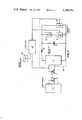
- FIG. 2 shows, diagrammatically, a speed control circuit provided for the winch motor
- FIG. 3 is a graph of the winch motor torque speed characteristics, illustrating operation of the control circuit.
- a mining machine 1 comprises a body 2 mounted for movement along a face conveyor 3 and having at each end a cutting drum 4.
- the body 2 houses an electric cutter motor 5, driving the two drums through cutting unit gear boxes 6, and an electric winch motor 7, which by means of a winch motor gear box 8 hauls the machine along the conveyor.
- the winch motor is a three-phase induction motor comprising a stator winding 19, which is fed from the multiphase alternating current source via switch gear 10, and a wound rotor 17 having respective phase windings, across which is connected a circuit 100 having a three phase, full wave, rectifier bridge 11 which rectifies the rotor voltages, two parallel connected branches, one of which includes an impedance shown in the form of a resistor unit 12, and a filter consisting of an inductor 14 and a capacitor 15.
- the connection between the phase windings and the rectifier bridge will be by way of slip rings in order to keep the bulk of the rotor circuit (i.e.
- the resistor unit 12 is connected in series with a direct current thyristor chopper unit 13 and the branch incorporating these two series-connected components is connected to the rectifier bridge output via the filter comprising the inductor 14 and the capacitor 15.
- a further direct current thyristor chopper unit 16 is connected in the other branch so as to be in parallel with the chopper unit 13 and resistor unit 12 in series.
- the speed of the winch motor is governed by the effective impedance presented by the circuit 100 to the rotor windings, this effective impedance being controlled by a feedback branch from the wound rotor 17 comprising an overall logic unit 18.
- the rotor winding is on open circuit.
- the resistor unit 12 is connected into the rotor circuit which then has an effective resistance of R R (see FIG. 3).
- the rotor winding 17 is on short-circuit, the effective impedance presented by the circuit 100 then being R SC .
- the feedback loop is arranged to maintain the winch motor speed to within limits of a pre-set value, set in a speed controller 20. Denoting this value by S p , the motor is then operating at the point A (see FIG. 3) on the torque-speed characteristic which corresponds to the torque T R required from the motor, this characteristic corresponding to the effective resistance R R . If the torque required from the motor increases the speed drops and the motor is then operating at the point B.
- the logic unit 18 monitors the frequency of the rotor current or voltage, or the rotor voltage, which are related to the speed of the winch rotor, and responds to the detected drop in rotor speed to adjust the effective impedance presented by the circuit 100 to the nearest possible value of R - to restore the winch motor speed to S f .
- the motor is then at the operating point C.
- the logic unit 18 it would be possible for the logic unit 18 to be arranged to control the chopper units in such manner that the effective impedance can be varied in infinitesimal steps. In either case the effective impedance can be varied over the full operating range of the motor.
- the rotor circuit could be modified by using at least one branch, and preferably several parallel-connected branches, each comprising a resistor unit and a chopper unit connected in series and each having a different resistive value for the resistor unit.
- the logic unit would then be arranged to fire the appropriate thyristor or combination of thyristors so as to provide the desired effective impedance.
- control circuit such that a predetermined full-load torque cannot be exceeded.
- the motor speed can be maintained constant but when the full load torque is reached, the presented effective impedance for increasing load is varied to allow the motor speed to drop correspondingly.
- the motor could be arranged to operate at a predetermined constant torque and to adjust its speed according to the load. Where the motor is operated at constant torque, this has the advantage that because the rotor current is then substantially constant, the heat generated in the rotor windings is constant and this simplifies the cooling requirements of the rotor.
- the described speed control system could alternatively be used to control just the electric cutter motor, or even to control both the winch motor and the cutter motor.
- the inductor 14 and/or the capacitor 15 of the filter connected to the output of the rectifier bridge 11 may be omitted under certain circumstances.
- the inductance provided by the rotor phase windings is sufficient to provide a satisfactory current rise rate characteristic for the current through the thyristors once fired, no inductor is required in the filter.
- the capacitor 15 may be left out of the circuit if the current fluctuations in the rotor circuit can be tolerated.
- the feedback from the wound rotor can be by way of a tachogenerator.
- feedback control of the motor speed is to be preferred, it would be possible to dispense with these and to control the logic unit from a manual controller.
Landscapes
- Engineering & Computer Science (AREA)
- Mining & Mineral Resources (AREA)
- Mechanical Engineering (AREA)
- Life Sciences & Earth Sciences (AREA)
- General Life Sciences & Earth Sciences (AREA)
- Geochemistry & Mineralogy (AREA)
- Geology (AREA)
- Power Engineering (AREA)
- Control Of Ac Motors In General (AREA)
- Control Of Multiple Motors (AREA)
- Control Of Electric Motors In General (AREA)
- Drilling And Exploitation, And Mining Machines And Methods (AREA)
Abstract
A mining machine includes drive unit means for driving a haulage winch and a cutting tool of the machine, the drive unit means comprising a multi-phase induction motor with a wound rotor. In order to control the motor speed, the motor is provided with a circuit connected across the rotor windings and means for varying the effective impedance presented by the said circuit to the rotor windings.
Description
This invention relates to a mining machine.
It is common practice to drive the haulage winch of a mining machine by a fluid operated driving mechanism which usually comprises a hydraulic pump and a hydraulic motor. The pump and motor are employed so that an infinitely variable speed output can be obtained and hence the feed rate from the pump to the motor adjusted to suit changes in the hardness of the material which is being cut by the mining machine. Similarly, the rotary cutter(s) of the mining machine can be driven by such a hydraulic drive. However, hydraulic drives in use underground present difficulties as regards the risk of environmental dust at the coal face entering the hydraulic system, thereby increasing the need for maintenance.
According to the invention there is provided a mining machine including:
Drive unit means arranged to drive a haulage winch of the machine and a cutting tool of the machine, the drive unit means comprising a multi-phase induction motor with a wound rotor,
Polyphase rectifier means arranged to receive the phase outputs of the motor and to combine these phase outputs to form a single unidirectional voltage output,
At least one branch connected to be supplied by the rectifier means, and
Means for varying the effected impedance presented by the said at least one branch to the rotor winding.
In this way, the motor speed over the full range of operating torques can be varied over the higher speed ranges up to maximum speed as well as over the lower speed ranges through which the motor passes transiently on starting up. The effective impedance presented to the rotor windings may be varied in discrete or infinitesimal steps.
Preferably, the effective impedance varying means comprises a feedback loop including control means arranged to control the effective impedance presented by the said circuit to the rotor windings in accordance with a predetermined criterion set in the control means. Alternatively, however, the effective impedance can be varied manually from a controller.
The drive unit means preferably comprises respective drive units arranged to drive the haulage winch and the cutting tool, at least one of the drive units comprising a multi-phase induction motor of the kind specified above. However, it could alternatively comprise a single drive unit arranged to drive both the winch and the cutting tool.
For a better understanding of the invention and to show how the same may be carried into effect, reference will now be made, by way of example, to the accompanying drawings, in which:
FIG. 1 illustrates diagrammatically a mining machine having an electric cutter motor and an electric winch motor,
FIG. 2 shows, diagrammatically, a speed control circuit provided for the winch motor, and
FIG. 3 is a graph of the winch motor torque speed characteristics, illustrating operation of the control circuit.
Referring to FIG. 1, a mining machine 1 comprises a body 2 mounted for movement along a face conveyor 3 and having at each end a cutting drum 4. The body 2 houses an electric cutter motor 5, driving the two drums through cutting unit gear boxes 6, and an electric winch motor 7, which by means of a winch motor gear box 8 hauls the machine along the conveyor.
With reference to FIG. 2, the winch motor is a three-phase induction motor comprising a stator winding 19, which is fed from the multiphase alternating current source via switch gear 10, and a wound rotor 17 having respective phase windings, across which is connected a circuit 100 having a three phase, full wave, rectifier bridge 11 which rectifies the rotor voltages, two parallel connected branches, one of which includes an impedance shown in the form of a resistor unit 12, and a filter consisting of an inductor 14 and a capacitor 15. Normally, the connection between the phase windings and the rectifier bridge will be by way of slip rings in order to keep the bulk of the rotor circuit (i.e. the rotor windings in combination with the circuit 100) separate from the rotor and stationary but this is not essential. The resistor unit 12 is connected in series with a direct current thyristor chopper unit 13 and the branch incorporating these two series-connected components is connected to the rectifier bridge output via the filter comprising the inductor 14 and the capacitor 15. A further direct current thyristor chopper unit 16 is connected in the other branch so as to be in parallel with the chopper unit 13 and resistor unit 12 in series.
The speed of the winch motor is governed by the effective impedance presented by the circuit 100 to the rotor windings, this effective impedance being controlled by a feedback branch from the wound rotor 17 comprising an overall logic unit 18. When neither thyristor is fired, the rotor winding is on open circuit. When the thyristor of chopper unit 13 is fired, the resistor unit 12 is connected into the rotor circuit which then has an effective resistance of RR (see FIG. 3). When the other thyristor alone is fired, the rotor winding 17 is on short-circuit, the effective impedance presented by the circuit 100 then being RSC. In addition, other effective impedance values, that is R- between RSC and RR and R+ between RR and infinite resistance can be selected by supplying square wave control pulses to one or other of the thyristors of the chopper units 13, 16, the value of R- or R+ depending on the ratio of the conducting to the non-conducting times of the thyristors. In a modification only one branch with a chopper unit, and with or without an impedance, is incorporated in the circuit 100.
The feedback loop is arranged to maintain the winch motor speed to within limits of a pre-set value, set in a speed controller 20. Denoting this value by Sp, the motor is then operating at the point A (see FIG. 3) on the torque-speed characteristic which corresponds to the torque TR required from the motor, this characteristic corresponding to the effective resistance RR. If the torque required from the motor increases the speed drops and the motor is then operating at the point B. The logic unit 18 monitors the frequency of the rotor current or voltage, or the rotor voltage, which are related to the speed of the winch rotor, and responds to the detected drop in rotor speed to adjust the effective impedance presented by the circuit 100 to the nearest possible value of R- to restore the winch motor speed to Sf. The motor is then at the operating point C.
It is preferred from the practical point of view to adjust the effective impedance in discrete steps but it would be possible for the logic unit 18 to be arranged to control the chopper units in such manner that the effective impedance can be varied in infinitesimal steps. In either case the effective impedance can be varied over the full operating range of the motor.
Instead of obtaining values of R- and R+ by supplying square wave pulses to the thyristors, the rotor circuit could be modified by using at least one branch, and preferably several parallel-connected branches, each comprising a resistor unit and a chopper unit connected in series and each having a different resistive value for the resistor unit. The logic unit would then be arranged to fire the appropriate thyristor or combination of thyristors so as to provide the desired effective impedance. Clearly the larger the number of branches the greater is the number of discrete effective impedances which can be presented to the rotor windings.
It is preferred to arrange the control circuit such that a predetermined full-load torque cannot be exceeded. Thus, up to that torque, the motor speed can be maintained constant but when the full load torque is reached, the presented effective impedance for increasing load is varied to allow the motor speed to drop correspondingly. In another arrangement, the motor could be arranged to operate at a predetermined constant torque and to adjust its speed according to the load. Where the motor is operated at constant torque, this has the advantage that because the rotor current is then substantially constant, the heat generated in the rotor windings is constant and this simplifies the cooling requirements of the rotor.
The described speed control system could alternatively be used to control just the electric cutter motor, or even to control both the winch motor and the cutter motor.
It is to be noted that the inductor 14 and/or the capacitor 15 of the filter connected to the output of the rectifier bridge 11 may be omitted under certain circumstances. Thus, where the inductance provided by the rotor phase windings is sufficient to provide a satisfactory current rise rate characteristic for the current through the thyristors once fired, no inductor is required in the filter. Moreover, the capacitor 15 may be left out of the circuit if the current fluctuations in the rotor circuit can be tolerated.
in a modification, the feedback from the wound rotor can be by way of a tachogenerator. Moreover, whilst feedback control of the motor speed is to be preferred, it would be possible to dispense with these and to control the logic unit from a manual controller.
Advantages of the described motor speed control arrangement are that it is simple constructionally and also is unlikely to be affected by environmental dust at the coal face.
Claims (19)
1. A mining machine including:
drive unit means for driving a haulage winch of the machine and a cutting tool of the machine, the drive unit means including a multi-phase induction motor with a wound rotor,
polyphase rectifier means arranged to receive the phase outputs of said motor and to combine said phase outputs to form a single unidirectional voltage output,
at least one branch connected to be supplied by the rectifier means, and
means for varying the effective impedance presented by said at least one branch to the rotor windings.
2. A mining machine according to claim 1, wherein the effective impedance varying means comprises control means in a feedback branch for monitoring a parameter related to the performance of the drive unit means, said control means being arranged to control the said effective impedance in accordance with a predetermined criterion of drive unit performance set in the control means.
3. A mining machine according to claim 1, wherein the effective impedance varying means is manually operated.
4. A mining machine according to claim 1, wherein the effective impedance varying means comprises switch means, connected in said at least one branch of the said circuit, and control means for selectively controlling operation of the said switch means.
5. A mining machine according to claim 4, wherein said at least one branch includes an impedance.
6. A mining machine according to claim 4, wherein the control means is manually operated.
7. A mining machine according to claim 4, wherein the control means is incorporated in a feedback branch to monitor a parameter related to the performance of the drive unit means and is arranged to control operation of the switch means to satisfy a predetermined criterion of drive unit performance set in the control means.
8. A mining machine according to claim 2, wherein the criterion is that the motor speed is to remain constant within given limits.
9. A mining machine according to claim 2, wherein the criterion is that the full-load torque is not to exceed a predetermined torque, at which the motor-speed for increasing load is reduced so that said predetermined full-load torque is not exceeded.
10. A mining machine according to claim 2, wherein the criterion is that the motor speed is to remain constant within given limits up to a predetermined full-load torque, at which the motor speed for increasing load is reduced so that said predetermined full-load torque is not exceeded.
11. A mining machine according to claim 2, wherein the criterion is that the motor is to operate at a predetermined constant torque.
12. A mining machine according to claim 4, wherein the switch means, connected in said at least one branch, is in the form of a thyristor chopper unit and the control means incorporates a logic circuit arranged to supply control pulses selectively to said chopper unit.
13. A mining machine according to claim 4, wherein an inductance connected in series with said at least one branch.
14. A mining machine according to claim 4, wherein a further branch is connected in parallel with said at least one branch and comprises a capacitance.
15. A mining machine according to claim 1, wherein the polyphase rectifier means, said at least one branch and the effective impedance varying means are stationary and in connection with the rotor windings by way of slip rings.
16. A mining machine according to claim 1, wherein the induction motor is coupled to drive the said haulage winch alone.
17. A mining machine according to claim 1, wherein the induction motor is coupled to drive the said cutting tool alone.
18. A mining machine according to claim 1, wherein the induction motor is coupled to drive both the said haulage winch and the said cutting tool.
19. A mining machine according to claim 1, wherein the drive unit means comprises two multiphase induction motors with wound rotors, each said motor being provided with a respective polyphase rectifier means, with at least one respective, branch and with a respective effective impedance varying means, and the two motors being coupled to drive the said haulage winch and the said cutting tool respectively.
Applications Claiming Priority (2)
| Application Number | Priority Date | Filing Date | Title |
|---|---|---|---|
| GB39582/76 | 1976-09-23 | ||
| GB39582/76A GB1567641A (en) | 1976-09-23 | 1976-09-23 | Mining machine |
Publications (1)
| Publication Number | Publication Date |
|---|---|
| US4140951A true US4140951A (en) | 1979-02-20 |
Family
ID=10410342
Family Applications (1)
| Application Number | Title | Priority Date | Filing Date |
|---|---|---|---|
| US05/833,671 Expired - Lifetime US4140951A (en) | 1976-09-23 | 1977-09-15 | Mining machine |
Country Status (5)
| Country | Link |
|---|---|
| US (1) | US4140951A (en) |
| JP (1) | JPS5339903A (en) |
| DE (1) | DE2742915A1 (en) |
| FR (1) | FR2365689A1 (en) |
| GB (1) | GB1567641A (en) |
Cited By (2)
| Publication number | Priority date | Publication date | Assignee | Title |
|---|---|---|---|---|
| US4443748A (en) * | 1981-03-16 | 1984-04-17 | Boev Vladimir S | Method of controlling speed of at least one induction motor and device therefor |
| US4460862A (en) * | 1980-05-20 | 1984-07-17 | Espinosa Fausto L | Electronic speed and slowing down control with intrinsic safety |
Families Citing this family (1)
| Publication number | Priority date | Publication date | Assignee | Title |
|---|---|---|---|---|
| US8608250B2 (en) * | 2011-09-30 | 2013-12-17 | Joy Mm Delaware, Inc. | Slow turning drum for a miner |
Citations (2)
| Publication number | Priority date | Publication date | Assignee | Title |
|---|---|---|---|---|
| GB1087518A (en) * | 1965-08-02 | 1967-10-18 | Eickhoff Geb | Improvements in or relating to mining machines |
| US3657622A (en) * | 1970-04-30 | 1972-04-18 | Reuland Electric Co Industry | Control for adjusting and regulating the speed of an electric motor |
Family Cites Families (2)
| Publication number | Priority date | Publication date | Assignee | Title |
|---|---|---|---|---|
| DE1273669B (en) * | 1964-11-10 | 1968-07-25 | Licentia Gmbh | Arrangement for speed control of a three-phase asynchronous motor with slip ring rotor |
| FR1383635A (en) * | 1964-03-04 | 1964-12-24 | Licentia Gmbh | Method of controlling or adjusting the speed of asynchronous motors |
-
1976
- 1976-09-23 GB GB39582/76A patent/GB1567641A/en not_active Expired
-
1977
- 1977-09-15 US US05/833,671 patent/US4140951A/en not_active Expired - Lifetime
- 1977-09-22 FR FR7728636A patent/FR2365689A1/en active Granted
- 1977-09-22 JP JP11346077A patent/JPS5339903A/en active Pending
- 1977-09-23 DE DE19772742915 patent/DE2742915A1/en not_active Withdrawn
Patent Citations (2)
| Publication number | Priority date | Publication date | Assignee | Title |
|---|---|---|---|---|
| GB1087518A (en) * | 1965-08-02 | 1967-10-18 | Eickhoff Geb | Improvements in or relating to mining machines |
| US3657622A (en) * | 1970-04-30 | 1972-04-18 | Reuland Electric Co Industry | Control for adjusting and regulating the speed of an electric motor |
Cited By (2)
| Publication number | Priority date | Publication date | Assignee | Title |
|---|---|---|---|---|
| US4460862A (en) * | 1980-05-20 | 1984-07-17 | Espinosa Fausto L | Electronic speed and slowing down control with intrinsic safety |
| US4443748A (en) * | 1981-03-16 | 1984-04-17 | Boev Vladimir S | Method of controlling speed of at least one induction motor and device therefor |
Also Published As
| Publication number | Publication date |
|---|---|
| FR2365689A1 (en) | 1978-04-21 |
| DE2742915A1 (en) | 1978-03-30 |
| FR2365689B1 (en) | 1984-02-10 |
| JPS5339903A (en) | 1978-04-12 |
| GB1567641A (en) | 1980-05-21 |
Similar Documents
| Publication | Publication Date | Title |
|---|---|---|
| US4489261A (en) | Method and means for feeding electric energy to a portable power tool | |
| US5969957A (en) | Single phase to three phase converter | |
| US4019104A (en) | Variable speed induction motor | |
| US4476424A (en) | Variable speed induction motor drive system | |
| DE3002945A1 (en) | TRANSFORMER SYSTEM | |
| US5237494A (en) | Frequency inverting apparatus | |
| GB1578371A (en) | Method of and apparatus for regulating an asynchronous machine | |
| US3775652A (en) | Speed controls for electric motors | |
| US5777459A (en) | Induction electrical power generating system with variable numbers of poles and excitation frequency | |
| US4140951A (en) | Mining machine | |
| US4431956A (en) | Drive equipment | |
| JPS63257495A (en) | Electric source of motor-driven tool | |
| US3223911A (en) | Motor speed control system | |
| US3546550A (en) | Control circuit for braking speed control of induction motor | |
| US1476978A (en) | System of control | |
| US2066508A (en) | Electrical control system | |
| CA1281067C (en) | Static power conversion for adding d.c. motors | |
| US2462171A (en) | Generator fed motor control system | |
| US1889035A (en) | Hoist and crowd combined control system for electric shovels | |
| US4378587A (en) | Frequency converter apparatus | |
| US2295336A (en) | Control system for induction motors | |
| Hesla | Electrification of a major steel mill part 5: Scherbius and kraemer drives [history] | |
| US925385A (en) | System of transmission. | |
| DE3009994A1 (en) | Converter-fed motor control circuit - uses switching thyristor with two trigger stages for rapid changeover between driving and braking | |
| DE1538649B2 (en) | Generator system for alternating current of constant frequency with changing drive speed |
Legal Events
| Date | Code | Title | Description |
|---|---|---|---|
| AS | Assignment |
Owner name: INDRESCO INC., TEXAS Free format text: ASSIGNMENT OF ASSIGNORS INTEREST.;ASSIGNOR:DRESSER EUROPE S.A.;REEL/FRAME:006315/0959 Effective date: 19920903 |