US4127814A - Detector for discriminating between two metals on a relatively moving member by being positioned at a distance where it senses one but not the other - Google Patents
Detector for discriminating between two metals on a relatively moving member by being positioned at a distance where it senses one but not the other Download PDFInfo
- Publication number
- US4127814A US4127814A US05/648,023 US64802376A US4127814A US 4127814 A US4127814 A US 4127814A US 64802376 A US64802376 A US 64802376A US 4127814 A US4127814 A US 4127814A
- Authority
- US
- United States
- Prior art keywords
- detector
- distance
- reference mark
- detection
- members
- Prior art date
- Legal status (The legal status is an assumption and is not a legal conclusion. Google has not performed a legal analysis and makes no representation as to the accuracy of the status listed.)
- Expired - Lifetime
Links
Images


Classifications
-
- G—PHYSICS
- G01—MEASURING; TESTING
- G01B—MEASURING LENGTH, THICKNESS OR SIMILAR LINEAR DIMENSIONS; MEASURING ANGLES; MEASURING AREAS; MEASURING IRREGULARITIES OF SURFACES OR CONTOURS
- G01B7/00—Measuring arrangements characterised by the use of electric or magnetic techniques
- G01B7/02—Measuring arrangements characterised by the use of electric or magnetic techniques for measuring length, width or thickness
-
- F—MECHANICAL ENGINEERING; LIGHTING; HEATING; WEAPONS; BLASTING
- F15—FLUID-PRESSURE ACTUATORS; HYDRAULICS OR PNEUMATICS IN GENERAL
- F15B—SYSTEMS ACTING BY MEANS OF FLUIDS IN GENERAL; FLUID-PRESSURE ACTUATORS, e.g. SERVOMOTORS; DETAILS OF FLUID-PRESSURE SYSTEMS, NOT OTHERWISE PROVIDED FOR
- F15B15/00—Fluid-actuated devices for displacing a member from one position to another; Gearing associated therewith
- F15B15/20—Other details, e.g. assembly with regulating devices
- F15B15/28—Means for indicating the position, e.g. end of stroke
- F15B15/2815—Position sensing, i.e. means for continuous measurement of position, e.g. LVDT
- F15B15/2846—Position sensing, i.e. means for continuous measurement of position, e.g. LVDT using detection of markings, e.g. markings on the piston rod
-
- G—PHYSICS
- G01—MEASURING; TESTING
- G01D—MEASURING NOT SPECIALLY ADAPTED FOR A SPECIFIC VARIABLE; ARRANGEMENTS FOR MEASURING TWO OR MORE VARIABLES NOT COVERED IN A SINGLE OTHER SUBCLASS; TARIFF METERING APPARATUS; MEASURING OR TESTING NOT OTHERWISE PROVIDED FOR
- G01D5/00—Mechanical means for transferring the output of a sensing member; Means for converting the output of a sensing member to another variable where the form or nature of the sensing member does not constrain the means for converting; Transducers not specially adapted for a specific variable
- G01D5/12—Mechanical means for transferring the output of a sensing member; Means for converting the output of a sensing member to another variable where the form or nature of the sensing member does not constrain the means for converting; Transducers not specially adapted for a specific variable using electric or magnetic means
- G01D5/14—Mechanical means for transferring the output of a sensing member; Means for converting the output of a sensing member to another variable where the form or nature of the sensing member does not constrain the means for converting; Transducers not specially adapted for a specific variable using electric or magnetic means influencing the magnitude of a current or voltage
- G01D5/20—Mechanical means for transferring the output of a sensing member; Means for converting the output of a sensing member to another variable where the form or nature of the sensing member does not constrain the means for converting; Transducers not specially adapted for a specific variable using electric or magnetic means influencing the magnitude of a current or voltage by varying inductance, e.g. by a movable armature
Definitions
- the present invention relates to an apparatus for detecting the relative position of two members.
- a method of detecting the relative position of two members is already known, according to which a detector is fixed to one of the members and detects the thickness, which varies as a function of the position, of a coating covering the other member.
- the coating is continuous and covers, by a layer defined by an inner concial face and by an outer cylindrical face, the piston rod of a jack.
- the invention proposes a relative position detector which is much simpler than the detectors mentioned hereinabove.
- the detection member is disposed at a distance from the outer face of the first member which is shorter than the distance of detection of the material of said first member and greater than the distance of detection of the material of each reference mark.
- the reference mark is constituted by one of the ends of a bar, which extends in the direction of relative displacement of two members.
- the detection member is often constituted by an induction pick-up.
- FIG. 1 is an axial section through a jack provided with a detector according to the invention
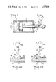
- FIGS. 2a and 2b schematically show an arrangement according to the invention, in two distinct configurations of the reference mark to be detected
- FIGS. 3a, 3b, 3c, 3d schematically show another arrangement according to the invention, in four distinct configurations of the reference mark;
- FIGS. 4 and 5 schematically show two applications of a detector according to the invention.
- FIG. 1 shows a jack which is constituted by a cylinder 1, defined by two screwed-down ends 2 in which a piston 3 is mounted to slide.
- a rod 4 of the piston is fast with the piston 3 and passes, in sealed manner, through one of the ends 2, a seal 5 being interposed between said rod and said end.
- a detector 6 is contained in a cavity 7 made in the end through which the piston rod 4 passes and is connected, by electrically conductive wires 8, to the dial 9 of a galvanometer.
- a reference mark 10 is made in the metal of the piston rod 4, near the end thereof. This reference mark is detectable by the detector 6.
- the rod is noted to be disposed at 4a, 4b, respectively, with respect to the detector 6.
- a reference mark 10a, 10b is made in this rod, which is flush with the cylindrical face 11a, 11b thereof.
- a protective chromium layer 12a, 12b covers the face 11a, 11b as well as said reference mark and has no effect on the detection made by the detector 6.
- the sensitive face 13 of the detector 6 is disposed at a distance d11 from the closest part of the face 11a, 11b and therefore from reference mark 10a, 10b.
- This distance d11 is on the one hand greater than the maximum distance d10 of detection of the reference mark 10a, 10b, on the other hand smaller than the distance d4 of detection of the material of the rod 4a, 4b.
- the reference mark 10b when the reference mark 10b is disposed between the outer face of the rod, disposed at 11b, and the sensitive face 13, it is distance d10 which must be taken into consideration. In the contrary case (FIG. 2a), it is distance d4 which must be considered.
- the needle of the dial 9 is shifted to 9a in FIG. 2a and is free from deviation and disposed at zero, at 9b, in FIG. 2b.
- the reference mark is constituted by a bar 14a, 14b, 14c, 14d, introduced into a longitudinal notch 15a, 15b, 15c, 15d made in the rod 16a, 16b, 16c, 16d which is movable with respect to the detector 6, respectively.
- the needle of the dial 9 is either shifted to 9a in FIGS. 3a and 3d, whilst the sensitive face 13 of the detector 6 is located straight above the face 11a, 11b, 11c, 11d of the rod, without interposition of the reference mark, or not shifted (9b) in FIGS. 3b and 3c, whilst said sensitive face 13 is located straight above the reference mark 14b, 14c, in the present case one or the other of the ends of this reference mark.
- the rod 4 comprises four reference marks 22, 23, 24, 25, each detectable by a particular detector 26a, 26b, 26c, 26d. With each detector is associated a double-throw switch 27a, 27b, 27c, 27d making it possible to switch on, or, on the contrary, neutralise the action of the corresponding detector.
- the displacements indicated between two reference marks correspond to the switching on of the following groups of two detectors:
- Detection functions by "all or nothing" and is finally not sensitive to a variation in distance between the sensitive face 13 and the face 11a or 11b of the rod, provided that this difference is sufficiently limited for d11 to remain between d4 and d10. If the rod 4a, 4b is made of steel and reference mark 10a, 10b made of bronze, d4 and d10 have very different values, which make it possible to tolerate already considerable variations of d11. A complicated electronic correction device is therefore not necessary for detecting the desired position with all the desired accuracy.
- the position signal is then constituted by the coincidence of one of the ends of the bar 14b or 14c with the detector 6.
- a control device 21 (FIG. 4) makes it possible to control the displacement between two successive reference marks, as a function of time. In this way, the equivalent of "cams" of various shapes is realised simply.
- the selection made by the switches of FIG. 5 enables the value and position of the useful stroke X 1 , X 2 or X 3 of a mobile member 4 to be instantaneously adjusted at the same time.
- the detection which is made, shown schematically by the move of needle 9a may be used for any desired application and, furthermore, enables a power circuit to be directly controlled without having to resort to the use of an amplifier. Machining is simplified by these various characteristics.
Abstract
This invention relates to a detector for detecting the relative position of two members, said detector being constituted by a reference mark made on a first member, by a detection member securely connected to the second member and influenced by the coincidence of position of the reference mark with itself, corresponding to said relative position. The reference mark is of substantially punctual type, distinct from other possible reference marks and separated from said other reference marks. One application of the present invention is the detection of the end of stroke of the piston of a jack.
Description
The present invention relates to an apparatus for detecting the relative position of two members.
A method of detecting the relative position of two members is already known, according to which a detector is fixed to one of the members and detects the thickness, which varies as a function of the position, of a coating covering the other member.
According to a certain known art, the coating is continuous and covers, by a layer defined by an inner concial face and by an outer cylindrical face, the piston rod of a jack.
In view of the sensitivity of the detector, and of the relative variation in distance from this detector to the outer surface of the coating, it is necessary, in order to obtain reliable values of the relative position, at least when this is possible as in the case of the rod of a jack, to compensate for the variation in distance on one side by the plurality of measurements of opposite sides, then to take into account the various data by a complicated and expensive electronic device.
This is naturally due to the continuous character of the measurement. Now, certain applications do not require continuity, and for such applications, the invention proposes a relative position detector which is much simpler than the detectors mentioned hereinabove.
It is therefore an object of the invention to provide an apparatus for detecting at least one relative position of two members which are movable with respect to each other, said detector being constituted by at least one reference mark made on the structure of a first of the two members, by a member for detecting the or each reference mark, secured to the second of said two members and influenced by the or each coincidence of position of the or each reference mark with itself, corresponding to the or each relative position, each reference mark is of substantially punctual type, distinct from other possible reference marks and separated from said other reference marks.
The detection member is disposed at a distance from the outer face of the first member which is shorter than the distance of detection of the material of said first member and greater than the distance of detection of the material of each reference mark.
The following arrangements are preferably adopted:
EACH REFERENCE MARK IS DISPOSED IN THE FIRST MEMBER AND IS FLUSH WITH THE OUTER FACE OF SAID FIRST MEMBER,
SAID OUTER FACE AND SAID REFERENCE MARK ARE COATED WITH A LAYER OF A SURFACE COATING, SUCH AS A LAYER OF CHROMIUM, WHICH HAS NO EFFECT ON THE DETECTION BY THE DETECTION MEMBER.
It is sometimes advantageous if the reference mark is constituted by one of the ends of a bar, which extends in the direction of relative displacement of two members.
Finally, the detection member is often constituted by an induction pick-up.
The invention will be more readily understood on reading the following description with reference to the accompanying drawings in which:
FIG. 1 is an axial section through a jack provided with a detector according to the invention;
FIGS. 2a and 2b schematically show an arrangement according to the invention, in two distinct configurations of the reference mark to be detected;
FIGS. 3a, 3b, 3c, 3d schematically show another arrangement according to the invention, in four distinct configurations of the reference mark;
FIGS. 4 and 5 schematically show two applications of a detector according to the invention.
Referring now to the drawings, FIG. 1 shows a jack which is constituted by a cylinder 1, defined by two screwed-down ends 2 in which a piston 3 is mounted to slide. A rod 4 of the piston is fast with the piston 3 and passes, in sealed manner, through one of the ends 2, a seal 5 being interposed between said rod and said end.
A detector 6 is contained in a cavity 7 made in the end through which the piston rod 4 passes and is connected, by electrically conductive wires 8, to the dial 9 of a galvanometer. In addition, a reference mark 10 is made in the metal of the piston rod 4, near the end thereof. This reference mark is detectable by the detector 6.
Referring to FIGS. 2a and 2b, the rod is noted to be disposed at 4a, 4b, respectively, with respect to the detector 6. A reference mark 10a, 10b is made in this rod, which is flush with the cylindrical face 11a, 11b thereof. In addition, a protective chromium layer 12a, 12b covers the face 11a, 11b as well as said reference mark and has no effect on the detection made by the detector 6. The sensitive face 13 of the detector 6 is disposed at a distance d11 from the closest part of the face 11a, 11b and therefore from reference mark 10a, 10b. This distance d11 is on the one hand greater than the maximum distance d10 of detection of the reference mark 10a, 10b, on the other hand smaller than the distance d4 of detection of the material of the rod 4a, 4b. On this subject, it should be noted that, when the reference mark 10b is disposed between the outer face of the rod, disposed at 11b, and the sensitive face 13, it is distance d10 which must be taken into consideration. In the contrary case (FIG. 2a), it is distance d4 which must be considered. The needle of the dial 9 is shifted to 9a in FIG. 2a and is free from deviation and disposed at zero, at 9b, in FIG. 2b.
Referring now to FIGS. 3a, 3b, 3c and 3d, the reference mark is constituted by a bar 14a, 14b, 14c, 14d, introduced into a longitudinal notch 15a, 15b, 15c, 15d made in the rod 16a, 16b, 16c, 16d which is movable with respect to the detector 6, respectively. The needle of the dial 9 is either shifted to 9a in FIGS. 3a and 3d, whilst the sensitive face 13 of the detector 6 is located straight above the face 11a, 11b, 11c, 11d of the rod, without interposition of the reference mark, or not shifted (9b) in FIGS. 3b and 3c, whilst said sensitive face 13 is located straight above the reference mark 14b, 14c, in the present case one or the other of the ends of this reference mark.
With reference to FIG. 4, there are four reference marks 17, 18, 19, 20 on the rod 4. These reference marks influence the detector 6 which is connected to a device 21 for controlling the displacement of the rod 4. This device 21, upon passage of each reference mark straight below the detector 6, controls the following displacement, so that the curve C representing the displacement X as a function of time T, is, in the example described, the one shown in FIG. 4.
In FIG. 5, the rod 4 comprises four reference marks 22, 23, 24, 25, each detectable by a particular detector 26a, 26b, 26c, 26d. With each detector is associated a double-throw switch 27a, 27b, 27c, 27d making it possible to switch on, or, on the contrary, neutralise the action of the corresponding detector. In this way, the displacements indicated between two reference marks correspond to the switching on of the following groups of two detectors:
Detectors in service: 26a and 26c; 26c and 26d; 26a and 26b
Corresponding displacement: X1 ; X2 ; X3
Reference marks in question: 22 and 24; 24 and 25; 22 and 23
Moreover, it is obvious that, as variants, several detectors could cooperate with a single reference mark, their being disposed, in that case, on the path of said reference mark and spaced from one another, each detector being associated with a switch.
The advantages of the devices described will now be set forth.
Fundamentally, it is understood on reading FIGS. 2a and 2b, that the position 4b of the rod 4 is detected when the distance d11 is greater than the distance d10 and that at the same moment the reference mark 10b is disposed straight below the sensitive face 13. When on the contrary the rod is located at 4a, the distance d11 is then shorter than the distance of detection of the rod; this detection is effected, the needle being shifted to 9a.
Detection functions by "all or nothing" and is finally not sensitive to a variation in distance between the sensitive face 13 and the face 11a or 11b of the rod, provided that this difference is sufficiently limited for d11 to remain between d4 and d10. If the rod 4a, 4b is made of steel and reference mark 10a, 10b made of bronze, d4 and d10 have very different values, which make it possible to tolerate already considerable variations of d11. A complicated electronic correction device is therefore not necessary for detecting the desired position with all the desired accuracy.
In this way, the end of stroke of the piston 3 of FIG. 1 is detected very simply and certainly by the coincidence of reference mark 10 and the detector 6.
When the reference mark is constituted by an elongated bar, the position signal is then constituted by the coincidence of one of the ends of the bar 14b or 14c with the detector 6.
Naturally, it is understood that a control device 21 (FIG. 4) makes it possible to control the displacement between two successive reference marks, as a function of time. In this way, the equivalent of "cams" of various shapes is realised simply.
Similarly, the selection made by the switches of FIG. 5 enables the value and position of the useful stroke X1, X2 or X3 of a mobile member 4 to be instantaneously adjusted at the same time.
It may also be noted that the detection which is made, shown schematically by the move of needle 9a, may be used for any desired application and, furthermore, enables a power circuit to be directly controlled without having to resort to the use of an amplifier. Machining is simplified by these various characteristics.
Claims (7)
1. A detector for detecting at least one relative position of two members which are movable with respect to each other, said detector comprising at least one reference mark made on the structure of a first of the two members, said first of the two members being formed of steel, said reference mark being of substantially punctual type and formed of bronze means capable of detecting the material of said first member within a first distance from the member and the material of said mark only within a second distance from the member which is smaller than said first distance, said detecting means being secured to the second of these two members and influenced by the coincidence of position of the reference mark with the detecting means, said detecting means being disposed at a distance from the outer face of the first member which is shorter than the distance of the detection of the material of said first member and greater than the distance of detection of the material of said reference mark.
2. A detector as claimed in claim 1, including a plurality of reference marks with each reference mark being disposed in the first member flush with the outer face thereof.
3. A detector as claimed in claim 2, wherein said outer face and said reference marks are coated with a layer of a surface coating which has no effect on the detection by the detection member.
4. A detector as claimed in claim 1, wherein the reference mark is constituted by one of the ends of a bar which extends in the direction of relative displacement of the two members.
5. A detector as claimed in claim 1, wherein the detection means is constituted by an induction pick-up.
6. A detector as defined in claim 2 wherein each of said reference marks is distinct from the other reference marks on said first member and separated from said other reference marks on said first member.
7. A detector as defined in claim 3 wherein said surface coating comprises a layer of chromium.
Applications Claiming Priority (2)
| Application Number | Priority Date | Filing Date | Title |
|---|---|---|---|
| FR7501154 | 1975-01-15 | ||
| FR7501154A FR2298081A1 (en) | 1975-01-15 | 1975-01-15 | TWO-PIECE RELATIVE POSITION DETECTOR |
Publications (1)
| Publication Number | Publication Date |
|---|---|
| US4127814A true US4127814A (en) | 1978-11-28 |
Family
ID=9149831
Family Applications (1)
| Application Number | Title | Priority Date | Filing Date |
|---|---|---|---|
| US05/648,023 Expired - Lifetime US4127814A (en) | 1975-01-15 | 1976-01-12 | Detector for discriminating between two metals on a relatively moving member by being positioned at a distance where it senses one but not the other |
Country Status (5)
| Country | Link |
|---|---|
| US (1) | US4127814A (en) |
| JP (1) | JPS5196345A (en) |
| BR (1) | BR7600205A (en) |
| DE (1) | DE2601274A1 (en) |
| FR (1) | FR2298081A1 (en) |
Cited By (10)
| Publication number | Priority date | Publication date | Assignee | Title |
|---|---|---|---|---|
| US4898027A (en) * | 1984-11-15 | 1990-02-06 | Industrie Riunite Spa | System for measuring the height above ground level of vehicles |
| US4909536A (en) * | 1988-10-24 | 1990-03-20 | Monroe Auto Equipment | Electronic height sensor |
| US5125681A (en) * | 1990-11-26 | 1992-06-30 | Monroe Auto Equipment Company | Method and apparatus for determining the displacement of a piston within a shock absorber |
| US5233294A (en) * | 1990-05-03 | 1993-08-03 | Alessandro Dreoni | Inductive proximity sensor and position transducer with a passive scale |
| US5652510A (en) * | 1994-06-03 | 1997-07-29 | Sony Corporation | Linear magnetic shaft position sensor monitoring changes in the inductance in a coil |
| US5886519A (en) * | 1997-01-29 | 1999-03-23 | Mitutoyo Corporation | Multi-scale induced current absolute position transducer |
| US5973494A (en) * | 1996-05-13 | 1999-10-26 | Mitutoyo Corporation | Electronic caliper using a self-contained, low power inductive position transducer |
| US6002250A (en) * | 1996-05-13 | 1999-12-14 | Mitutoyo Corporation | Electronic linear scale using a self-contained, low-power inductive position transducer |
| US6011389A (en) * | 1995-05-16 | 2000-01-04 | Mitutoyo Corporation | Induced current position transducer having a low power electronic circuit |
| ITUA20162127A1 (en) * | 2016-03-30 | 2017-09-30 | Giuliani S R L | APPARATUS AND METHOD FOR MEASURING DISPLACEMENT OF A CYLINDER PISTON |
Families Citing this family (6)
| Publication number | Priority date | Publication date | Assignee | Title |
|---|---|---|---|---|
| SE450295B (en) * | 1984-12-21 | 1987-06-15 | Enpece Ab | SET AND DEVICE FOR SEATING THE VOLUME OF A GAS IN A CONTAINER |
| DE3634730A1 (en) * | 1986-10-11 | 1988-04-21 | Klaus Huegler | Working cylinder, in particular pneumatic cylinder for components of automatic handling machines |
| DE3636871C2 (en) * | 1986-10-30 | 1995-08-31 | Beukenberg Maschf | Piston-cylinder unit with a position transmitter |
| DE3826561A1 (en) * | 1988-08-04 | 1990-02-08 | Rexroth Mannesmann Gmbh | Capacitive distance pick-up |
| US4944356A (en) * | 1988-12-28 | 1990-07-31 | Ford Motor Company | Steering system position detector |
| FR2655724B1 (en) * | 1989-12-12 | 1993-11-19 | Ferco Internal Usine Ferrures Ba | METHOD AND DEVICE FOR RECOGNIZING DIFFERENT ELEMENTS OF STANDARDIZED DIMENSION, ESPECIALLY FRAMES OF WINDOW FRAMES DURING MANUFACTURE. |
Citations (4)
| Publication number | Priority date | Publication date | Assignee | Title |
|---|---|---|---|---|
| US2628539A (en) * | 1945-01-04 | 1953-02-17 | Neergaard Leif Eric De | Method and means for recording and reproducing displacements |
| US2914756A (en) * | 1953-01-21 | 1959-11-24 | Heidenhain Johannes | Measuring apparatus comprising a graduated scale |
| US3176241A (en) * | 1961-04-07 | 1965-03-30 | Jimmie S Hogan | Magnetic switching device |
| US3473111A (en) * | 1965-04-29 | 1969-10-14 | Nederlanden Staat | Thin metal marking and method for detecting the same |
-
1975
- 1975-01-15 FR FR7501154A patent/FR2298081A1/en active Granted
-
1976
- 1976-01-12 US US05/648,023 patent/US4127814A/en not_active Expired - Lifetime
- 1976-01-13 JP JP51002521A patent/JPS5196345A/en active Pending
- 1976-01-14 BR BR7600205A patent/BR7600205A/en unknown
- 1976-01-15 DE DE19762601274 patent/DE2601274A1/en not_active Withdrawn
Patent Citations (4)
| Publication number | Priority date | Publication date | Assignee | Title |
|---|---|---|---|---|
| US2628539A (en) * | 1945-01-04 | 1953-02-17 | Neergaard Leif Eric De | Method and means for recording and reproducing displacements |
| US2914756A (en) * | 1953-01-21 | 1959-11-24 | Heidenhain Johannes | Measuring apparatus comprising a graduated scale |
| US3176241A (en) * | 1961-04-07 | 1965-03-30 | Jimmie S Hogan | Magnetic switching device |
| US3473111A (en) * | 1965-04-29 | 1969-10-14 | Nederlanden Staat | Thin metal marking and method for detecting the same |
Non-Patent Citations (1)
| Title |
|---|
| La Commande Electronique; Ministop Detector de Proximite Electronique; Dossier Techniqu de l'Electrict; Panelle Techniques, Z-Az; 2nd Ed., Apr. 1973. * |
Cited By (11)
| Publication number | Priority date | Publication date | Assignee | Title |
|---|---|---|---|---|
| US4898027A (en) * | 1984-11-15 | 1990-02-06 | Industrie Riunite Spa | System for measuring the height above ground level of vehicles |
| US4909536A (en) * | 1988-10-24 | 1990-03-20 | Monroe Auto Equipment | Electronic height sensor |
| US5233294A (en) * | 1990-05-03 | 1993-08-03 | Alessandro Dreoni | Inductive proximity sensor and position transducer with a passive scale |
| US5125681A (en) * | 1990-11-26 | 1992-06-30 | Monroe Auto Equipment Company | Method and apparatus for determining the displacement of a piston within a shock absorber |
| US5652510A (en) * | 1994-06-03 | 1997-07-29 | Sony Corporation | Linear magnetic shaft position sensor monitoring changes in the inductance in a coil |
| US5811969A (en) * | 1994-06-03 | 1998-09-22 | Sony Corporation | Shaft position detection sensor monitoring changes in coil inductance |
| US6011389A (en) * | 1995-05-16 | 2000-01-04 | Mitutoyo Corporation | Induced current position transducer having a low power electronic circuit |
| US5973494A (en) * | 1996-05-13 | 1999-10-26 | Mitutoyo Corporation | Electronic caliper using a self-contained, low power inductive position transducer |
| US6002250A (en) * | 1996-05-13 | 1999-12-14 | Mitutoyo Corporation | Electronic linear scale using a self-contained, low-power inductive position transducer |
| US5886519A (en) * | 1997-01-29 | 1999-03-23 | Mitutoyo Corporation | Multi-scale induced current absolute position transducer |
| ITUA20162127A1 (en) * | 2016-03-30 | 2017-09-30 | Giuliani S R L | APPARATUS AND METHOD FOR MEASURING DISPLACEMENT OF A CYLINDER PISTON |
Also Published As
| Publication number | Publication date |
|---|---|
| FR2298081A1 (en) | 1976-08-13 |
| DE2601274A1 (en) | 1976-07-22 |
| BR7600205A (en) | 1976-08-31 |
| FR2298081B1 (en) | 1979-05-25 |
| JPS5196345A (en) | 1976-08-24 |
Similar Documents
| Publication | Publication Date | Title |
|---|---|---|
| US4127814A (en) | Detector for discriminating between two metals on a relatively moving member by being positioned at a distance where it senses one but not the other | |
| KR910001839B1 (en) | Checking machine of location | |
| US5187475A (en) | Apparatus for determining the position of an object | |
| US5742161A (en) | Method and device for detecting displacement of valve rod movement in an electropneumatic position regulator with at least one proximity sensor | |
| US4552028A (en) | Device for measuring force | |
| GB1595127A (en) | Transducer for angular and linear measurement | |
| EP0119673A1 (en) | Transducers | |
| US5461311A (en) | Rod axial position detector including plural scales wherein nonmagnetized portions have differing spacing and differing depths and means for calculating the absolute position are provided | |
| US5497083A (en) | Rod axial position detector including a first scale having equidistant magnetic parts and a second scale having unequally distant parts and differing field strengths | |
| EP3834061B1 (en) | Computer input devices | |
| US5243187A (en) | High resolution absolute encoder for position measurement | |
| KR870011591A (en) | Improved non-contact pattern sensor | |
| US7332915B2 (en) | Sensor system and method of operating the same | |
| SE460928B (en) | ABSOLUTELY MEASURING SCALE SYSTEM | |
| GB2074325A (en) | Level Indicators for Electrically Conductive Liquids or Loose Materials | |
| US5350955A (en) | Apparatus for position detection and verification thereof using pulse patterns having sequentially unique properties | |
| US5708367A (en) | Digital position sensor | |
| JPS63250802A (en) | Indicator of displacement and position | |
| US4982106A (en) | Device for detecting at least one variable relating to the movement of a movable body | |
| US4459751A (en) | Selection element housing for incremental measuring apparatus | |
| RU97117889A (en) | SELF-INSTALLING SENSOR | |
| JPH086259Y2 (en) | Linear position detector | |
| EP0618373A1 (en) | Position indicator | |
| JPS63279101A (en) | Non-contact displacement detector | |
| GB1586807A (en) | Method and apparatus for effecting contactless and continuous measurement of the position of a stationery or moving body of circular cross section |