US4113341A - Electrical connector having provision for circuit components - Google Patents
Electrical connector having provision for circuit components Download PDFInfo
- Publication number
- US4113341A US4113341A US05/824,023 US82402377A US4113341A US 4113341 A US4113341 A US 4113341A US 82402377 A US82402377 A US 82402377A US 4113341 A US4113341 A US 4113341A
- Authority
- US
- United States
- Prior art keywords
- wire
- terminal
- receiving
- receptacle
- lead wire
- Prior art date
- Legal status (The legal status is an assumption and is not a legal conclusion. Google has not performed a legal analysis and makes no representation as to the accuracy of the status listed.)
- Expired - Lifetime
Links
- 239000004020 conductor Substances 0.000 claims description 19
- 230000004888 barrier function Effects 0.000 claims description 17
- 238000002788 crimping Methods 0.000 claims description 3
- WABPQHHGFIMREM-UHFFFAOYSA-N lead(0) Chemical compound [Pb] WABPQHHGFIMREM-UHFFFAOYSA-N 0.000 claims description 2
- 239000002184 metal Substances 0.000 claims description 2
- 230000013011 mating Effects 0.000 claims 12
- 238000005057 refrigeration Methods 0.000 description 7
- 210000005069 ears Anatomy 0.000 description 6
- 238000009413 insulation Methods 0.000 description 3
- 238000010348 incorporation Methods 0.000 description 2
- 230000014759 maintenance of location Effects 0.000 description 2
- 230000004308 accommodation Effects 0.000 description 1
- 238000005452 bending Methods 0.000 description 1
- 230000005540 biological transmission Effects 0.000 description 1
- 239000011810 insulating material Substances 0.000 description 1
- 238000012423 maintenance Methods 0.000 description 1
- 238000010008 shearing Methods 0.000 description 1
Images

Classifications
-
- H—ELECTRICITY
- H01—ELECTRIC ELEMENTS
- H01R—ELECTRICALLY-CONDUCTIVE CONNECTIONS; STRUCTURAL ASSOCIATIONS OF A PLURALITY OF MUTUALLY-INSULATED ELECTRICAL CONNECTING ELEMENTS; COUPLING DEVICES; CURRENT COLLECTORS
- H01R13/00—Details of coupling devices of the kinds covered by groups H01R12/70 or H01R24/00 - H01R33/00
- H01R13/66—Structural association with built-in electrical component
- H01R13/6608—Structural association with built-in electrical component with built-in single component
- H01R13/6641—Structural association with built-in electrical component with built-in single component with diode
-
- H—ELECTRICITY
- H01—ELECTRIC ELEMENTS
- H01R—ELECTRICALLY-CONDUCTIVE CONNECTIONS; STRUCTURAL ASSOCIATIONS OF A PLURALITY OF MUTUALLY-INSULATED ELECTRICAL CONNECTING ELEMENTS; COUPLING DEVICES; CURRENT COLLECTORS
- H01R13/00—Details of coupling devices of the kinds covered by groups H01R12/70 or H01R24/00 - H01R33/00
- H01R13/66—Structural association with built-in electrical component
-
- H—ELECTRICITY
- H01—ELECTRIC ELEMENTS
- H01R—ELECTRICALLY-CONDUCTIVE CONNECTIONS; STRUCTURAL ASSOCIATIONS OF A PLURALITY OF MUTUALLY-INSULATED ELECTRICAL CONNECTING ELEMENTS; COUPLING DEVICES; CURRENT COLLECTORS
- H01R11/00—Individual connecting elements providing two or more spaced connecting locations for conductive members which are, or may be, thereby interconnected, e.g. end pieces for wires or cables supported by the wire or cable and having means for facilitating electrical connection to some other wire, terminal, or conductive member, blocks of binding posts
- H01R11/01—Individual connecting elements providing two or more spaced connecting locations for conductive members which are, or may be, thereby interconnected, e.g. end pieces for wires or cables supported by the wire or cable and having means for facilitating electrical connection to some other wire, terminal, or conductive member, blocks of binding posts characterised by the form or arrangement of the conductive interconnection between the connecting locations
-
- H—ELECTRICITY
- H01—ELECTRIC ELEMENTS
- H01R—ELECTRICALLY-CONDUCTIVE CONNECTIONS; STRUCTURAL ASSOCIATIONS OF A PLURALITY OF MUTUALLY-INSULATED ELECTRICAL CONNECTING ELEMENTS; COUPLING DEVICES; CURRENT COLLECTORS
- H01R13/00—Details of coupling devices of the kinds covered by groups H01R12/70 or H01R24/00 - H01R33/00
- H01R13/46—Bases; Cases
- H01R13/502—Bases; Cases composed of different pieces
- H01R13/506—Bases; Cases composed of different pieces assembled by snap action of the parts
-
- H—ELECTRICITY
- H01—ELECTRIC ELEMENTS
- H01R—ELECTRICALLY-CONDUCTIVE CONNECTIONS; STRUCTURAL ASSOCIATIONS OF A PLURALITY OF MUTUALLY-INSULATED ELECTRICAL CONNECTING ELEMENTS; COUPLING DEVICES; CURRENT COLLECTORS
- H01R13/00—Details of coupling devices of the kinds covered by groups H01R12/70 or H01R24/00 - H01R33/00
- H01R13/56—Means for preventing chafing or fracture of flexible leads at outlet from coupling part
- H01R13/567—Traverse cable outlet or wire connection
-
- H—ELECTRICITY
- H01—ELECTRIC ELEMENTS
- H01R—ELECTRICALLY-CONDUCTIVE CONNECTIONS; STRUCTURAL ASSOCIATIONS OF A PLURALITY OF MUTUALLY-INSULATED ELECTRICAL CONNECTING ELEMENTS; COUPLING DEVICES; CURRENT COLLECTORS
- H01R4/00—Electrically-conductive connections between two or more conductive members in direct contact, i.e. touching one another; Means for effecting or maintaining such contact; Electrically-conductive connections having two or more spaced connecting locations for conductors and using contact members penetrating insulation
- H01R4/10—Electrically-conductive connections between two or more conductive members in direct contact, i.e. touching one another; Means for effecting or maintaining such contact; Electrically-conductive connections having two or more spaced connecting locations for conductors and using contact members penetrating insulation effected solely by twisting, wrapping, bending, crimping, or other permanent deformation
- H01R4/18—Electrically-conductive connections between two or more conductive members in direct contact, i.e. touching one another; Means for effecting or maintaining such contact; Electrically-conductive connections having two or more spaced connecting locations for conductors and using contact members penetrating insulation effected solely by twisting, wrapping, bending, crimping, or other permanent deformation by crimping
-
- H—ELECTRICITY
- H01—ELECTRIC ELEMENTS
- H01R—ELECTRICALLY-CONDUCTIVE CONNECTIONS; STRUCTURAL ASSOCIATIONS OF A PLURALITY OF MUTUALLY-INSULATED ELECTRICAL CONNECTING ELEMENTS; COUPLING DEVICES; CURRENT COLLECTORS
- H01R4/00—Electrically-conductive connections between two or more conductive members in direct contact, i.e. touching one another; Means for effecting or maintaining such contact; Electrically-conductive connections having two or more spaced connecting locations for conductors and using contact members penetrating insulation
- H01R4/24—Connections using contact members penetrating or cutting insulation or cable strands
- H01R4/2416—Connections using contact members penetrating or cutting insulation or cable strands the contact members having insulation-cutting edges, e.g. of tuning fork type
- H01R4/242—Connections using contact members penetrating or cutting insulation or cable strands the contact members having insulation-cutting edges, e.g. of tuning fork type the contact members being plates having a single slot
Definitions
- This invention relates to an electrical connector which serves to connect wires or other conductors to terminal pins or the like and which has provision for optionally connecting a circuit component in series with each wire.
- the herein disclosed embodiment of the invention is particularly intended to connect wires to contact pins in a refrigerator but other uses of the invention will be apparent to those skilled in the connector art.
- control circuits for refrigeration compressors have been developed which require only two conductors with a diode in series with one of these conductors and the three position connectors of the prior art are not suitable for these more modern compressors. Rather, a connector is required which provides a means for incorporating the diode in series with one of the conductors and which otherwise satisfies the requirements of connectors for refrigeration compressors.
- a connector comprising a housing which is dimensioned to receive two terminal members.
- Each terminal member has a wire crimp portion which is crimped onto the end of a wire and a pin receptacle portion which receives the contact pin which extends from a header of a compressor enclosure.
- the wire crimp portion and the pin receptacle portion are spaced-apart and are connected by an integral strap member.
- the wire crimp and pin receptacle portions of each terminal have a lead wire-receiving means which is adapted to receive a lead wire extending from a diode located between the crimp portion and the receptacle portion.
- This feature permits the diode to be connected in series with one of the wires by inserting its lead wires into the lead wire-receiving members and removing the strap.
- the wire extending to the connector which is to be connected directly to a contact pin is simply crimped onto an identical terminal member and the connecting strap is not removed.
- a further object is to provide an improved connector for pin headers of the type used in refrigeration compressor enclosures.
- a further object is to provide a compact and reliable connector having a minimum number of parts.
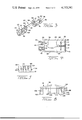
- FIG. 1 is a perspective view of a connector assembly in accordance with the invention.
- FIG. 2 is a perspective exploded view, partially in section, showing the various parts of the connector assembly.
- FIG. 3 is a perspective view of an uncrimped terminal member.
- FIG. 4 is a plan view of the housing body.
- FIG. 5 is an end view of a housing body.
- FIG. 6 is a side view of the housing cover.
- a connector assembly 2 in accordance with the invention serves to connect first and second wires 4, 6 to first and second terminal pins 8, 10 which extend from a header 12 which, in turn, is mounted in the wall of an enclosure 14.
- the enclosure may contain a refrigeration compressor and the wires 4, 6 serve as the control circuits and power supply for the compressor.
- the connector assembly 2 comprises generally a prismatic housing body 16 and a housing cover 18 which is assembled to the body after the terminals and the diode have been positioned in the body.
- the housing body 16 is advantageously of a molded insulating material and has a floor or base 20 from which sidewalls 19, 22, 24, and 26 extend. These sidewalls define an enclosure in which the ends of the wires, the terminals, and the diode are contained as shown in FIG. 2.
- a first sidewall 19 serves as a wire-receiving sidewall and has spaced-apart wire-receiving notches 21 extending downwardly from its upper edge.
- the second sidewall 22 is opposite to the sidewall 19 and the additional sidewalls 24, 26 extend along the sides of the base as shown.
- the sidewalls 24, 26 are inwardly offset as shown at 28 so that the right hand end of the housing body is relatively more narrow than the wire-receiving end.
- An internal barrier wall 30 extends from the sidewall 22 partially towards the wire-receiving sidewall 19 and this barrier wall defines two side-by-side stalls 32, 34 which receive the pin receptacle portions 54 of the terminal members. Openings 46 are provided in the base 20 in the vicinity of these stalls to permit entry of the contact pins 8, 10 and downwardly facing shoulders 48 are provided on the sides of these stalls for cooperation with retention ears of the pin receptacle members 54 as will be described below.
- barrier wall 36 which extends from the internal surface of wire-receiving sidewall 19 and towards the barrier wall 30.
- This latter barrier wall 36 provides two side-by-side stalls which receive the ends of the wires 4, 6 and crimp portions of the terminal members 52.
- Spaced-apart bosses 38, 40 are provided on the base 20 adjacent to the stall 32 and intermediate the ends of the housing and serve as stops or locating means for portions of the terminals as shown in FIG. 2 and as described more fully below.
- a relatively high boss 42 is provided on each side of the barrier wall 36 and these bosses 32 have notches extending inwardly from their upper ends which receive the wire crimps on the ends of the wire 4, 6. These notches are constricted as shown at 43 adjacent to their upper ends so that the crimped terminals can be moved downwardly into the notch, but upward movement of the terminals will be restrained.
- the terminal members 50 comprise a wire crimp portion 52 and a pin receptacle portion 54, these two portions of the terminal members being axially aligned and spaced-apart as shown and are connected to each other by an integral strap member 56.
- These terminal members are manufactured by stamping and forming of conductive sheet metal and are produced as an endless strip for maximum economy.
- the wire crimp portion 52 of each terminal member comprises a common web 58 having the one end thereof upstanding sidewalls 60 which are intended for crimping onto the insulation of a wire as shown in FIG. 2. Sidewalls 62 are also provided for crimping onto the conducting core of a wire and establishing electrical contact therewith.
- the web 58 has an extension 64 which projects from the end of the wire core crimp portion and a lead wire-receiving plate member 66 extends upwardly, as viewed in FIG. 2, from the end of this web extension.
- the lead wire-receiving portion has a wire-receiving slot 68 extending downwardly from its upper free end so that the lead of the diode can be connected to the terminal member by merely moving the lead into this wire-receiving slot.
- the pin receptacle portion 54 is also generally U-shaped having a web 72 and sidewalls 76 extending from its side edges.
- An opening 74 is provided in the web for reception of a contact pin and the opposed surfaces of the sidewalls 76 are spaced-apart by a distance such that they will establish electrical contact with an inserted pin.
- Retention ears 78 are struck outwardly from the corners of the sidewalls and these ears lodge against the previously identified shoulders 48 in the stalls 32, 34 to retain the pin receptacle portions of the terminal members in the stalls.
- Pin receptacle portion 54 also has a web extension 80 and a lead wire-receiving means as previously described at 66 integral therewith.
- the connecting strap 56 is integral with laterally extending ears 86 of the two web extensions 64, 80 and this strap is bent upwardly to minimize the width of the terminal member.
- the diode 88 is generally cylindrical and has lead wires 90, 92 extending from its ends. It should be mentioned at this point that careless manipulation of these lead wires will quite often result in damage to the diode 88 and these wires must, therefore, be protected against bending or other abuse when the diode is located in the housing.
- the wire crimp portion 52 of a terminal member 50 is crimped onto the stripped end of the wire 4 and the connecting strap portion of this terminal member is then removed by simply shearing across the ear portions 86.
- the wire crimp portion is then positioned in the stall on the right as viewed in FIG. 2 of the barrier wall 36 and the pin receiving portion 54 is positioned in the stall 32 by moving this pin receptacle downwardly into the stall until the ears lodge beneath the shoulders 48.
- the lead wires 90, 92 of the diode 88 are then trimmed and the diode is positioned between the lead wire-receiving portions 66, 82 with the lead wires themselves disposed in the wire-receiving slots of these lead like members.
- the plate-like wire-receiving members are disposed against the bosses 38, 40 and that the pin receptacle portion 54 is further restrained against movement parallel to the axes of the lead wires 90, 92 by internal surfaces of sidewall 32 and between shoulders 48.
- the rearwardly facing edge 25 of the insulation crimp portion 60 of the terminal is substantially against the internal surface of the sidewall 19 so that if a tensile force is applied to the wire 4, this tensile force will not be transmitted to the diode lead 92.
- the wire 6 is connected to the wire crimp portion 52 of another terminal member 50 and this terminal member is simply moved downwardly from the position shown in FIG. 2 so that its pin receptacle portion 54 is disposed in the stall 34 and the wire crimp portion is disposed in the stall on the left of the barrier wall 36.
- the cover member is simply assembled to the housing body by downward movement thereof from the position shown in FIG. 2.
- the cover member 18 has an external upper surface 94 and a central upwardly arched section 96 which provides internal clearance in the diode 88 which projects above the upper edges of the sidewall in the housing body.
- the cover member On its underside, the cover member has depending clamping portions 98 which are dimensioned to enter the notches 21 in the wire-receiving sidewall 19 and which have lower ends which bear against the insulation of the wires 4, 6. This feature provides added strain relief means for the wires and minimizes the transmission of any tensile forces which may be applied to the wires.
- the cover member is secured to the housing body by depending latch arms 100 which have openings 102 therein and these openings are dimensioned to receive latching ears 104 which project from the external surface of the housing body.
- Arms 106 extend downwardly from the underside of the cover member and are received in openings 108 in the connector body portion 20.
- the openings 108 are adjacent to the barrier walls 30, 36 and an additional barrier wall 110 is integral with the cover member and extends between the depending arms 106.
- Barrier wall 110 is laterally offset in its central portions as shown to provide clearance for the cylindrical portion of the circuit component 88.
- the barrier wall 110, the arms 106, and the barrier walls 30, 36 in the connector body all cooperate to divide the interior of the housing into two separate compartments which is desirable from an electrical standpoint.
- a connector in accordance with the invention satisfies all the requirements of compactness and reliability as described above and as required in connectors used for the pin headers mounted in compressor enclosures.
- a distinct advantage of the invention is that only two identical terminal members 50 are required for each connector although one of the terminal members serves to connect the diode 88 in series with one of the conductors. It will be apparent that this feature of permitting optional incorporation of a diode can be used under other circumstances where circuit components are wired in series with conductors extending to a connector.
Landscapes
- Details Of Connecting Devices For Male And Female Coupling (AREA)
- Coupling Device And Connection With Printed Circuit (AREA)
- Connector Housings Or Holding Contact Members (AREA)
- Connection Or Junction Boxes (AREA)
- Multi-Conductor Connections (AREA)
Priority Applications (14)
| Application Number | Priority Date | Filing Date | Title |
|---|---|---|---|
| US05/824,023 US4113341A (en) | 1977-08-12 | 1977-08-12 | Electrical connector having provision for circuit components |
| GB7830036A GB2002597B (en) | 1977-08-12 | 1978-07-17 | Electrical connector |
| CA307,593A CA1085478A (en) | 1977-08-12 | 1978-07-18 | Electrical connector with a housing containing a receptacle contact registering with an aperature in the housing |
| AU38188/78A AU514454B2 (en) | 1977-08-12 | 1978-07-19 | Electrical connector |
| NL787807769A NL7807769A (nl) | 1977-08-12 | 1978-07-20 | Elektrische verbindingsinrichting. |
| IT7826278A IT1097893B (it) | 1977-08-12 | 1978-07-28 | Connettore elettrico |
| JP9267978A JPS5431592A (en) | 1977-08-12 | 1978-07-31 | Electric connector and connector parts |
| MX174414A MX144968A (es) | 1977-08-12 | 1978-08-03 | Conector electrico mejorado |
| BE78189761A BE869590A (fr) | 1977-08-12 | 1978-08-07 | Connecteur electrique, notamment pour compresseur de refrigerateur |
| FR7823245A FR2400266A1 (fr) | 1977-08-12 | 1978-08-07 | Connecteur electrique, notamment pour compresseur de refrigerateur |
| SE7808524A SE7808524L (sv) | 1977-08-12 | 1978-08-09 | Kontaktdon |
| BR7805189A BR7805189A (pt) | 1977-08-12 | 1978-08-11 | Conetor eletrico e membro conetor para o mesmo |
| ES472529A ES472529A1 (es) | 1977-08-12 | 1978-08-11 | Perfeccionamientos introducidos en un conectador electrico |
| DE19782835568 DE2835568A1 (de) | 1977-08-12 | 1978-08-14 | Elektrischer verbinder und anschlusselement dafuer |
Applications Claiming Priority (1)
| Application Number | Priority Date | Filing Date | Title |
|---|---|---|---|
| US05/824,023 US4113341A (en) | 1977-08-12 | 1977-08-12 | Electrical connector having provision for circuit components |
Publications (1)
| Publication Number | Publication Date |
|---|---|
| US4113341A true US4113341A (en) | 1978-09-12 |
Family
ID=25240405
Family Applications (1)
| Application Number | Title | Priority Date | Filing Date |
|---|---|---|---|
| US05/824,023 Expired - Lifetime US4113341A (en) | 1977-08-12 | 1977-08-12 | Electrical connector having provision for circuit components |
Country Status (14)
| Country | Link |
|---|---|
| US (1) | US4113341A (it) |
| JP (1) | JPS5431592A (it) |
| AU (1) | AU514454B2 (it) |
| BE (1) | BE869590A (it) |
| BR (1) | BR7805189A (it) |
| CA (1) | CA1085478A (it) |
| DE (1) | DE2835568A1 (it) |
| ES (1) | ES472529A1 (it) |
| FR (1) | FR2400266A1 (it) |
| GB (1) | GB2002597B (it) |
| IT (1) | IT1097893B (it) |
| MX (1) | MX144968A (it) |
| NL (1) | NL7807769A (it) |
| SE (1) | SE7808524L (it) |
Cited By (37)
| Publication number | Priority date | Publication date | Assignee | Title |
|---|---|---|---|---|
| US4205891A (en) * | 1978-08-09 | 1980-06-03 | Gulf & Western Manufacturing Company | Radio frequency interference suppressor connector |
| US4206962A (en) * | 1978-06-05 | 1980-06-10 | Amp Incorporated | Data/logic connector |
| US4375311A (en) * | 1980-11-05 | 1983-03-01 | Amp Incorporated | Diode connector |
| US4386819A (en) * | 1981-08-31 | 1983-06-07 | Amp Incorporated | RF Shielded assembly having capacitive coupling feature |
| US4413871A (en) * | 1981-12-10 | 1983-11-08 | Amp Incorporated | Earth connection connector having provision for an electrical component |
| US4447105A (en) * | 1982-05-10 | 1984-05-08 | Illinois Tool Works Inc. | Terminal bridging adapter |
| US4478472A (en) * | 1981-10-26 | 1984-10-23 | Rca Corporation | Electrical connector |
| US4549105A (en) * | 1983-01-07 | 1985-10-22 | Mitsubishi Denki Kabushiki Kaisha | Submergible motor including circuit element encased in molded plug |
| US4568902A (en) * | 1982-04-02 | 1986-02-04 | Smit Transformatoren B.V. | Contact piece for air-cooled transformers having conductive lines |
| US4580001A (en) * | 1983-04-13 | 1986-04-01 | Sharp Kabushiki Kaisha | Packaging device for electronic component |
| US4679885A (en) * | 1986-08-01 | 1987-07-14 | General Motors Corporation | Electrical component packaging assembly |
| US4719473A (en) * | 1985-02-08 | 1988-01-12 | Canon Kabushiki Kaisha | Recording apparatus |
| US4846720A (en) * | 1987-12-23 | 1989-07-11 | Song Jae C | Balun trans and feeder line connecting device of antenna matching adapter for television set |
| US4952169A (en) * | 1989-06-27 | 1990-08-28 | Amp Incorporated | Sealed electrical connector employing insulation displacement terminals |
| US5030132A (en) * | 1987-12-17 | 1991-07-09 | Amp Incorporated | Bidirectional insulation displacement electrical contact terminal |
| EP0600418A1 (en) * | 1992-12-01 | 1994-06-08 | The Whitaker Corporation | Shunted airbag connector |
| FR2703521A1 (fr) * | 1993-03-30 | 1994-10-07 | Amphenol Tuchel Elect | Adaptateur pour un connecteur à fiches. |
| EP0647988A1 (de) * | 1993-09-28 | 1995-04-12 | Siemens Aktiengesellschaft | Steckverbinder-Kupplung |
| WO1995024749A1 (en) * | 1994-03-08 | 1995-09-14 | Starpoint Electrics Limited | Electrical assemblies |
| US5639258A (en) * | 1995-05-15 | 1997-06-17 | Berg Technology, Inc. | Electrical connector including means for terminating wires |
| WO1999008346A1 (en) * | 1997-08-06 | 1999-02-18 | Starpoint Electrics Limited | Electrical assemblies and fasteners |
| EP0924808A1 (en) * | 1997-12-15 | 1999-06-23 | Molex Incorporated | Shielded electrical connector assembly with grounding system |
| FR2780205A1 (fr) * | 1998-06-22 | 1999-12-24 | Sylea | Dispositif de liaison d'un conducteur electrique de derivation sur un conducteur principal |
| US6095867A (en) * | 1998-09-21 | 2000-08-01 | Rockwell Technologies, Llc | Method and apparatus for transmitting power and data signals via a network connector system including integral power capacitors |
| FR2795241A1 (fr) * | 1999-06-16 | 2000-12-22 | Cinch Connecteurs Sa | Dispositif de liaison electrique entre un conducteur electrique principal et au moins un conducteur electrique secondaire |
| US6179644B1 (en) | 1997-11-07 | 2001-01-30 | Rockwell Technologies, Llc | Power and data network system media architecture |
| US6220890B1 (en) | 1999-03-25 | 2001-04-24 | Illinois Tool Works Inc. | Electrical switch connector assembly |
| US6232557B1 (en) | 1997-11-07 | 2001-05-15 | Rockwell Technologies, Llc | Network cable and modular connection for such a cable |
| US6315528B1 (en) * | 1999-05-27 | 2001-11-13 | Scroll Technologies | Terminal connection in small area of scroll compressor and method for carrying out same |
| US6488539B1 (en) * | 2001-09-20 | 2002-12-03 | Illinois Tool Works Inc. | Electrical connector |
| US20040063357A1 (en) * | 2002-10-01 | 2004-04-01 | Baldor Electric Company | Power plug housing |
| US7063570B1 (en) | 2005-02-25 | 2006-06-20 | Delphi Technologies, Inc. | Electrical connector and component packaging assembly |
| US20090251877A1 (en) * | 2008-04-08 | 2009-10-08 | Yazaki Corporation | Electronic part-connecting structure |
| US20110081808A1 (en) * | 2009-10-07 | 2011-04-07 | Japan Aviation Electronics Industry, Limited | Contact and connection unit provided with the contact |
| US8202124B1 (en) | 2011-03-11 | 2012-06-19 | Lear Corporation | Contact and receptacle assembly for a vehicle charging inlet |
| EP2495815A1 (de) * | 2011-03-04 | 2012-09-05 | CCS Technology, Inc. | Kontaktfeder einer Verteilereinrichtung einer Telekommunikationsanlage |
| US20200127423A1 (en) * | 2017-06-22 | 2020-04-23 | Te Connectivity Industrial Gmbh | Electrical Plug With A Protective Conductor Contact And Protective Conductor Connector Element Formed Integrally Therewith For Grounding Exterior Parts |
Families Citing this family (11)
| Publication number | Priority date | Publication date | Assignee | Title |
|---|---|---|---|---|
| GB2160034B (en) * | 1984-04-05 | 1987-11-18 | Pressac Ltd | Electrical sockets for use with cathode ray tubes |
| GB8431962D0 (en) * | 1984-12-18 | 1985-01-30 | Ariel Pressings Ltd | Electrical connectors |
| GB8432238D0 (en) * | 1984-12-20 | 1985-01-30 | Starpoint Electrics Ltd | Lampholder |
| DE8812558U1 (de) * | 1988-10-03 | 1989-01-05 | Stachera, Rainer, 2390 Flensburg | Transport-Ronde |
| DE8812556U1 (de) | 1988-10-05 | 1988-11-17 | Grote & Hartmann Gmbh & Co Kg, 5600 Wuppertal | Vielpoliger Stecker |
| GB2250645B (en) * | 1990-12-06 | 1994-10-12 | Amp Inc | An electrical connector and an electrical terminal therefor |
| GB2260229B (en) * | 1991-10-03 | 1995-06-21 | Whitaker Corp | An electrical connector |
| NL9300386A (nl) * | 1992-09-23 | 1994-10-03 | Whitaker Corp | Electrische connector en electrische aansluitklem daarvoor. |
| DE4324841A1 (de) * | 1993-07-23 | 1995-01-26 | Grote & Hartmann | Verfahren und Vorrichtung zur Stromversorgung optionaler, elektrisch angetriebener Sonderausstattungseinrichtungen, z. B. in einem Kraftfahrzeug, einem elektrisch betriebenen Haushaltsgerät oder dergleichen |
| GB2293696A (en) * | 1994-07-28 | 1996-04-03 | Mod Tap Ltd | ID contact and connector for telecommunications |
| CN114520421B (zh) * | 2020-11-20 | 2024-07-09 | 泰科电子(上海)有限公司 | 连接器 |
Citations (3)
| Publication number | Priority date | Publication date | Assignee | Title |
|---|---|---|---|---|
| US2848706A (en) * | 1953-11-17 | 1958-08-19 | Carl W Besserer | Electrical connector |
| US3917377A (en) * | 1974-05-15 | 1975-11-04 | Essex International Inc | Connector assembly and receptacle terminal therefor |
| CA1007275A (en) * | 1974-04-29 | 1977-03-22 | Canadian General Electric Company Limited | Safety female plug connector for an immersion heater |
Family Cites Families (2)
| Publication number | Priority date | Publication date | Assignee | Title |
|---|---|---|---|---|
| IN139599B (it) * | 1972-11-21 | 1976-07-03 | Bunker Ramo | |
| US3842396A (en) * | 1973-04-27 | 1974-10-15 | Amp Inc | Cluster block housing and pin receptacle |
-
1977
- 1977-08-12 US US05/824,023 patent/US4113341A/en not_active Expired - Lifetime
-
1978
- 1978-07-17 GB GB7830036A patent/GB2002597B/en not_active Expired
- 1978-07-18 CA CA307,593A patent/CA1085478A/en not_active Expired
- 1978-07-19 AU AU38188/78A patent/AU514454B2/en not_active Expired
- 1978-07-20 NL NL787807769A patent/NL7807769A/xx not_active Application Discontinuation
- 1978-07-28 IT IT7826278A patent/IT1097893B/it active
- 1978-07-31 JP JP9267978A patent/JPS5431592A/ja active Pending
- 1978-08-03 MX MX174414A patent/MX144968A/es unknown
- 1978-08-07 FR FR7823245A patent/FR2400266A1/fr active Granted
- 1978-08-07 BE BE78189761A patent/BE869590A/xx not_active IP Right Cessation
- 1978-08-09 SE SE7808524A patent/SE7808524L/xx unknown
- 1978-08-11 ES ES472529A patent/ES472529A1/es not_active Expired
- 1978-08-11 BR BR7805189A patent/BR7805189A/pt unknown
- 1978-08-14 DE DE19782835568 patent/DE2835568A1/de not_active Withdrawn
Patent Citations (3)
| Publication number | Priority date | Publication date | Assignee | Title |
|---|---|---|---|---|
| US2848706A (en) * | 1953-11-17 | 1958-08-19 | Carl W Besserer | Electrical connector |
| CA1007275A (en) * | 1974-04-29 | 1977-03-22 | Canadian General Electric Company Limited | Safety female plug connector for an immersion heater |
| US3917377A (en) * | 1974-05-15 | 1975-11-04 | Essex International Inc | Connector assembly and receptacle terminal therefor |
Cited By (46)
| Publication number | Priority date | Publication date | Assignee | Title |
|---|---|---|---|---|
| US4206962A (en) * | 1978-06-05 | 1980-06-10 | Amp Incorporated | Data/logic connector |
| US4205891A (en) * | 1978-08-09 | 1980-06-03 | Gulf & Western Manufacturing Company | Radio frequency interference suppressor connector |
| US4375311A (en) * | 1980-11-05 | 1983-03-01 | Amp Incorporated | Diode connector |
| US4386819A (en) * | 1981-08-31 | 1983-06-07 | Amp Incorporated | RF Shielded assembly having capacitive coupling feature |
| US4478472A (en) * | 1981-10-26 | 1984-10-23 | Rca Corporation | Electrical connector |
| US4413871A (en) * | 1981-12-10 | 1983-11-08 | Amp Incorporated | Earth connection connector having provision for an electrical component |
| US4568902A (en) * | 1982-04-02 | 1986-02-04 | Smit Transformatoren B.V. | Contact piece for air-cooled transformers having conductive lines |
| US4447105A (en) * | 1982-05-10 | 1984-05-08 | Illinois Tool Works Inc. | Terminal bridging adapter |
| US4549105A (en) * | 1983-01-07 | 1985-10-22 | Mitsubishi Denki Kabushiki Kaisha | Submergible motor including circuit element encased in molded plug |
| US4580001A (en) * | 1983-04-13 | 1986-04-01 | Sharp Kabushiki Kaisha | Packaging device for electronic component |
| US4719473A (en) * | 1985-02-08 | 1988-01-12 | Canon Kabushiki Kaisha | Recording apparatus |
| US4679885A (en) * | 1986-08-01 | 1987-07-14 | General Motors Corporation | Electrical component packaging assembly |
| US5030132A (en) * | 1987-12-17 | 1991-07-09 | Amp Incorporated | Bidirectional insulation displacement electrical contact terminal |
| US4846720A (en) * | 1987-12-23 | 1989-07-11 | Song Jae C | Balun trans and feeder line connecting device of antenna matching adapter for television set |
| US4952169A (en) * | 1989-06-27 | 1990-08-28 | Amp Incorporated | Sealed electrical connector employing insulation displacement terminals |
| EP0600418A1 (en) * | 1992-12-01 | 1994-06-08 | The Whitaker Corporation | Shunted airbag connector |
| US5435754A (en) * | 1992-12-01 | 1995-07-25 | The Whitaker Corporation | Shunted airbag connector |
| FR2703521A1 (fr) * | 1993-03-30 | 1994-10-07 | Amphenol Tuchel Elect | Adaptateur pour un connecteur à fiches. |
| EP0647988A1 (de) * | 1993-09-28 | 1995-04-12 | Siemens Aktiengesellschaft | Steckverbinder-Kupplung |
| GB2301493B (en) * | 1994-03-08 | 1998-03-11 | Starpoint Electrics Ltd | Electrical assemblies |
| WO1995024749A1 (en) * | 1994-03-08 | 1995-09-14 | Starpoint Electrics Limited | Electrical assemblies |
| GB2301493A (en) * | 1994-03-08 | 1996-12-04 | Starpoint Electrics Ltd | Electrical assemblies |
| US5639258A (en) * | 1995-05-15 | 1997-06-17 | Berg Technology, Inc. | Electrical connector including means for terminating wires |
| US5746620A (en) * | 1995-05-15 | 1998-05-05 | Berg Technology, Inc. | Electrical connector including means for terminating wires |
| WO1999008346A1 (en) * | 1997-08-06 | 1999-02-18 | Starpoint Electrics Limited | Electrical assemblies and fasteners |
| GB2343064A (en) * | 1997-08-06 | 2000-04-26 | Starpoint Electrics Ltd | Electrical assemblies and fasteners |
| GB2343064B (en) * | 1997-08-06 | 2002-03-06 | Starpoint Electrics Ltd | Electrical assemblies |
| US6179644B1 (en) | 1997-11-07 | 2001-01-30 | Rockwell Technologies, Llc | Power and data network system media architecture |
| US6232557B1 (en) | 1997-11-07 | 2001-05-15 | Rockwell Technologies, Llc | Network cable and modular connection for such a cable |
| EP0924808A1 (en) * | 1997-12-15 | 1999-06-23 | Molex Incorporated | Shielded electrical connector assembly with grounding system |
| FR2780205A1 (fr) * | 1998-06-22 | 1999-12-24 | Sylea | Dispositif de liaison d'un conducteur electrique de derivation sur un conducteur principal |
| US6095867A (en) * | 1998-09-21 | 2000-08-01 | Rockwell Technologies, Llc | Method and apparatus for transmitting power and data signals via a network connector system including integral power capacitors |
| US6220890B1 (en) | 1999-03-25 | 2001-04-24 | Illinois Tool Works Inc. | Electrical switch connector assembly |
| US6315528B1 (en) * | 1999-05-27 | 2001-11-13 | Scroll Technologies | Terminal connection in small area of scroll compressor and method for carrying out same |
| FR2795241A1 (fr) * | 1999-06-16 | 2000-12-22 | Cinch Connecteurs Sa | Dispositif de liaison electrique entre un conducteur electrique principal et au moins un conducteur electrique secondaire |
| US6488539B1 (en) * | 2001-09-20 | 2002-12-03 | Illinois Tool Works Inc. | Electrical connector |
| US20040063357A1 (en) * | 2002-10-01 | 2004-04-01 | Baldor Electric Company | Power plug housing |
| US7063570B1 (en) | 2005-02-25 | 2006-06-20 | Delphi Technologies, Inc. | Electrical connector and component packaging assembly |
| US20090251877A1 (en) * | 2008-04-08 | 2009-10-08 | Yazaki Corporation | Electronic part-connecting structure |
| US7695306B2 (en) * | 2008-04-08 | 2010-04-13 | Yazaki Corporation | Electronic part-connecting structure |
| US20110081808A1 (en) * | 2009-10-07 | 2011-04-07 | Japan Aviation Electronics Industry, Limited | Contact and connection unit provided with the contact |
| US8353725B2 (en) * | 2009-10-07 | 2013-01-15 | Japan Aviation Electronics Industry, Limited | Contact and connection unit provided with the contact |
| EP2495815A1 (de) * | 2011-03-04 | 2012-09-05 | CCS Technology, Inc. | Kontaktfeder einer Verteilereinrichtung einer Telekommunikationsanlage |
| US8202124B1 (en) | 2011-03-11 | 2012-06-19 | Lear Corporation | Contact and receptacle assembly for a vehicle charging inlet |
| US20200127423A1 (en) * | 2017-06-22 | 2020-04-23 | Te Connectivity Industrial Gmbh | Electrical Plug With A Protective Conductor Contact And Protective Conductor Connector Element Formed Integrally Therewith For Grounding Exterior Parts |
| US11177616B2 (en) * | 2017-06-22 | 2021-11-16 | Te Connectivity Industrial Gmbh | Electrical plug with a protective conductor contact and protective conductor connector element formed integrally therewith for grounding exterior parts |
Also Published As
| Publication number | Publication date |
|---|---|
| FR2400266B1 (it) | 1982-05-14 |
| GB2002597A (en) | 1979-02-21 |
| AU3818878A (en) | 1980-01-24 |
| IT7826278A0 (it) | 1978-07-28 |
| MX144968A (es) | 1981-12-08 |
| CA1085478A (en) | 1980-09-09 |
| BR7805189A (pt) | 1979-04-24 |
| ES472529A1 (es) | 1979-04-01 |
| FR2400266A1 (fr) | 1979-03-09 |
| NL7807769A (nl) | 1979-02-14 |
| BE869590A (fr) | 1979-02-07 |
| SE7808524L (sv) | 1979-02-13 |
| GB2002597B (en) | 1982-01-13 |
| DE2835568A1 (de) | 1979-02-22 |
| AU514454B2 (en) | 1981-02-12 |
| IT1097893B (it) | 1985-08-31 |
| JPS5431592A (en) | 1979-03-08 |
Similar Documents
| Publication | Publication Date | Title |
|---|---|---|
| US4113341A (en) | Electrical connector having provision for circuit components | |
| US4820192A (en) | Connecting block construction | |
| US4221458A (en) | Electrical connector receptacle | |
| US4656378A (en) | Motor stator and connector for making connections to stator windings | |
| EP0104013B1 (en) | Multi-contact electrical connector | |
| US4193654A (en) | Electrical connector receptacles | |
| US5096442A (en) | Compact electrical connector | |
| US5697815A (en) | Electrical connectors | |
| US4109992A (en) | Connector for compressor header | |
| US4557544A (en) | Terminal for connecting a lead wire to a coil wire | |
| US5203716A (en) | Terminal block for printed circuit boards | |
| US4460234A (en) | Double-ended modular jack | |
| EP0279508B1 (en) | Electrical terminal | |
| US4315664A (en) | Modular jack | |
| US4865564A (en) | Wall mounted connecting block | |
| US3336567A (en) | Electrical connector | |
| US5133672A (en) | Insulation displacement terminal | |
| KR100354449B1 (ko) | 전기커넥터및그하우징 | |
| EP1385232B1 (en) | Electrical connector assembly, plug connector and receptacle connector | |
| EP0109297B1 (en) | Improvements in electrical contact members and electrical connector assemblies | |
| US4952155A (en) | Electrical connector | |
| US3671925A (en) | Pressure lock and release terminal for an electrical receptacle | |
| US4512620A (en) | Mass termination electrical connector | |
| US4583813A (en) | Low profile electrical connector assembly | |
| US4490004A (en) | Connector for connecting insulated wires to a circuit board |