US410040A - -start - Google Patents
-start Download PDFInfo
- Publication number
- US410040A US410040A US410040DA US410040A US 410040 A US410040 A US 410040A US 410040D A US410040D A US 410040DA US 410040 A US410040 A US 410040A
- Authority
- US
- United States
- Prior art keywords
- plate
- needles
- circular
- sinker
- guide
- Prior art date
- Legal status (The legal status is an assumption and is not a legal conclusion. Google has not performed a legal analysis and makes no representation as to the accuracy of the status listed.)
- Expired - Lifetime
Links
- 238000009940 knitting Methods 0.000 description 6
- 239000004744 fabric Substances 0.000 description 5
- 230000000630 rising effect Effects 0.000 description 3
- 239000011435 rock Substances 0.000 description 3
- 229910001369 Brass Inorganic materials 0.000 description 1
- ATJFFYVFTNAWJD-UHFFFAOYSA-N Tin Chemical compound [Sn] ATJFFYVFTNAWJD-UHFFFAOYSA-N 0.000 description 1
- 210000001015 abdomen Anatomy 0.000 description 1
- 239000010951 brass Substances 0.000 description 1
- 230000000994 depressogenic effect Effects 0.000 description 1
- 239000002184 metal Substances 0.000 description 1
- 230000000717 retained effect Effects 0.000 description 1
Images


Classifications
-
- D—TEXTILES; PAPER
- D04—BRAIDING; LACE-MAKING; KNITTING; TRIMMINGS; NON-WOVEN FABRICS
- D04B—KNITTING
- D04B25/00—Warp knitting machines not otherwise provided for
- D04B25/02—Tubular machines
Definitions
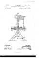
- FIG. l is a front view of my improved traversed warp machine with the plates carrying the operati11g-instruments shown in seetion.
- Fig. lfL is an enlarged sectional detail view. of the lower front portion of the machine.
- Figs. 2, 2, and 2b are vertical sectional views of the machine, looking from the right-hand end.
- Fig. 3 is a plan view showing the relative positions of a sole-plate carrying two revolving circular guide-plates, two
- FIG. 4 shows a sectional View, drawn to an enlarged scale, of the operating-instruments in their operative positions.
- Figs. 5 to 13 and Figs. 4., 4., 4, 4, 6, and 1Ia illustrate portions of the machine, shown separately and severally referred to hereinafter; and Figs. I4, l5, and I6 show enlarged side views of the cams employed.
- Each machine consists of two end standards A, connected at their upper ends by a tie-bar A and at their lower ends by two stretchers A2.
- the standards have brackets a a projecting from them, which carry bearings b Z9 for two shafts B and B.
- the shaft B is provided with a ily-wheel B2, and a fast pulley A3 and a loose pulley A4 for a drivingstrap.
- This shaft B carries three pairs of cams O6, C7, F3, F4, and G4, each pair of which operates a pair of truck-bearing levers C4 F? G3, (see Figs. I, 2, 2, and 2b,)the two central pairs of which are free to move partly round upon the shaft B', which is parallel with the cam-shaft.
- the two outerlevers forming the third pair are secured to and rock with theA A, at its center, a boss c projects, in which a vertical rod O is secured, on the lower end of which a circular plate C slides vertically.
- This plate is provided onits circumference with leads carrying sinker-hooks O2, Fig. 4b,
- Each. lever C4 is operated by a cam C, t
- FIG. 4 A side view and outer edge view of one of the presser-bits CB are shown at Fig. 4, and
- a doubleflanged circular bed D which is support-ed IOO by being securely fixed to the vertical rod O by means of a pin D7, which is passed into holes in the tubular center e of the bed D and a corresponding hole in the rod O, as Shown in Figs. l, l, and 2.
- the lower iiauge of the bed D is provided with a circular brass sley D', in which tricks are cut. These tricks radiate from the center and in each a slide D2 moves to and fro.
- Each slide D2 is provided with a lockerplate D3, the sides of which clip the slide and rock upon an axlepin f, secured in it.
- Each locker-plate when in the position shown at Figs.
- l, 2, and 4f secures a lead of needles.
- One of these leads is shown in plan at Fig. 6%
- the lower edge of the lead is grooved, as shown, to receive the top of the slide, upon which it is firmly pressed by the locker-plate. Vhen a needle is broken, the lead may be readily released by simply turning the locker-plate up into the position shown by dotted lines at Fig. 4. The lead can then be taken off and a new one substituted.
- Each lead is provided with the requisite number of bearded or latch needles.
- One of the slides D2 is shown in plan and side view at Fig. 4d
- one of the locker-plates D3 is shown in plan and side view at Fig.
- each lead of needles is shown in side view, plan, and under side view at Fig. Gf.
- Bearded needles are shown in the drawings. The outer ends of t-hese needles pass to and fro between lthe sinkers at each course, being operated by the following means:
- each of the whole circle of slides is moved inward and outward by right-angled jacks D4.
- a jack is shown in edge view at Fig. 7.
- the lower end of each jack carries a stud g, which takes into a hole g in the back end of the slide, as shown in Fig. 4.
- Above the lower stud each jack is provided with a projecting stud 71, on one side, which liesin a groove t', cut in the circumference of a slotted sley D5, Figs. l, 2, 4, and l, in which the jacks rock.
- This sley is secured to the upper iiange D6 of the iiXed circular bed, before described, and shown separately in plan at Fig. 8.
- the jacks are kept in position by a loose ring E encircling the whole of them.
- the inner edge of the ring rests upon the outer upper edge of the sley D5, and has four arms secured to it, the lower ends of which are attached to a light ring E', which rests upon the tops of the needle-leads, before named.
- This ring prevents a needlelead from rising up when the fabric is pressed off the needles, and thereby avoids breakage.
- the circular plate O carries two vertical pins O8, which slide vertically in corresponding holes in the lower flange of the circular bed D, as shown in Fig. 4L. This arrangement prevents vibration and insures the sinkers always being in a central position between the next adjacent needles.
- the jacks D4 are rocked by their inner ends taking into a groove cut in the circumference of a circular plate F (Shown separately in plan, Fig. 9.)
- This circular plate has a rising-and-falling movement communicated to it by the following means:
- the boss 7c of the plate F carries a short axle-pin m on each side, which pins are connected to the lower ends of the vertical rods F', having their upper ends hinged to a second pair of truck-bearing levers F2, which are free to turn upon the shaft B', before named, as shown in Fig.
- the sole-bar carries two circular guideplates G6 G7, one above and the other below it, and each plate is provided with leads of thread-guides G8, the guides in which radiate toward the center of the machine.
- One such lead of guides is shown in plan at Fig. l0.
- the upper guide-plate GG as it is revolved or traversed, slides upon the sole-bar, and the lower guide G7 is kept in position by and slides upon four clips G, secured to the solebar.
- Either plate can be revolved the reverse way to the other, orboth together either way, by the following means:
- Each guide-plate has teeth cut round the whole of its circumference. Only a few of these teeth are shown in the drawings, Figs. 3 and ll.
- the teeth of the upper guide-plate engage with a toothed wheel G10, and the teeth of the lower guide-plate engage with a toothed wheel G11.
- the wheel G10 is shown in gear with a portion of the guide-plate G6 at Fig. ll.
- Each of the toothed wheels is secured on the lower end of a vertical shaft p, which revolves in a bearing G14, capable of adj ustment, as hereinafter explained, on a bearing-bracket G12, which is secured to the solebar, and shown in plan at Fig. 8.
- the upper end of each shaft revolves in a bearing G13.
- the shafts are each provided with a toothed wheel H. A portion only of these teeth are shown in plan at Fig. 3. Each wheel is partially revolved by a worm H of the cam-shaft B.
- the worm-wheel at the right end o f the machine is shown in side view at Fig. 12 and in edge view at Fig. 13.
- the upper circular guide-plate is provided with as many bearing-brackets I as are required, the number varying with the diameter of the guide-plates.
- the lower guideplate is provided with a like number of bearing-brackets I.
- Each bracket ⁇ carries one end of two spindles I2, upon which two next adjacent warp-spools K revolve.
- One end of each spool is provided with a grooved pulley, around which an iudiarubber band I3 is passed, by which the required tension is put upon the warp-threads in the usual way.
- the spindles are retained in the bearings on the upper guiderplate by split pins I4, and in those of the lower guide-plate by springs I5, both of which are shown at Fig. 4.
- the whole of the warp-threads either traverse or are revolved with their respective guide-bars. When the guide-plates are revolved, they move in a reverse direction, as indicated by the arrows shown in Fig. 3.
- the highest positions of the guide-leads G8, the sinker-hooks C2, and presser-bits C3 when the work has been knocked over the heads of the needles by the completion of the inner movement of the slides D2 are indicated in Figli by dottedlines.
- the back position of one such slide is also shown by the dotted lines at Fig. 4.
- the guidebars G6 G7 have been moved to their highest position by the upward movementof the solebar G5, they are traversed in a reverse direction to each other, as shown by the arrows in Fig. 3, over one needle.
- the guides are then passed down through the needles, and are traversed under two needles at each course to makeplain traversed warp fabric.
- the guide-bars do not move vertically while being revolved; but when the guides are at their highest position both guide-bars are traversed to carry the guides over the requisite number of needles before being lowered through the needles.
- the plate G6 When patterned warp fabrics are required to be made, the plate G6 is traversed at each course by means of the toothed wheel G10, the wheel G11 being removed from the machine to allow the plate G7 to be operated by a pattern-wheel H2.
- the bar G7 is provided with a projecting stop-pieee H3, which is held to the pattern-wheel by means of a spring H4, one end of which is attached to it, the other end of the spring being attached to a stud projecting from the sole bar or plate G5.
- guide-plate G7 is traversed intermittently under two needles and over one as the pattern-wheel is revolved.
- the machine is provided with a work-roller tov receive the fabric below the circular sinkerguides being down in their relative positions,
- I am enabled to make single traversed net with one plate or both plates, or double traversed net with the two plates being reversely traversed; or I can make patterned warp lace, taffeta, or knotted fabrics by changing the pattern-wheels according to requirements.
Landscapes
- Engineering & Computer Science (AREA)
- Textile Engineering (AREA)
- Knitting Machines (AREA)
Description
(No Model.) 9 Sheets-Sheet l1.
W. START. CIRCULAR WARP vKNITTING MACHINE'.v
100.410.040. Y Patented Aug. 27, 1080.
l/ ylllllllllllllllll/f N4 PETERS. PhmmLimagmpher, wnshingmn. uA a 9 Sheets-Sheet 2.
. uw gw,
Patented Aug. 27, 1889.
W; START. CIRCULAR WARP KNITTINC MACHINE.
(No Model.)r
(No Model.) 9 Sheets-Sheet 3.
l W. START. CIRCULAR WARP KNITTING MACHINE.
No. 410,040. Patented Auge?, 1889.
mw l? M5@ (Ne Medel.) 4 0 sheets-sheet 4.
W. START. GIRGULAR WARP KNITTING MACHINE. Ne. 410,040. Peeented Aug. 27, 1880.
2f/@32 I j @D (No Model.) 9 sheets-sheet 5. W. START.
CIRCULAR WARP KNITTINC MACHINE. No. 410,040. Patented Aug. 27, 1889.`
(No Model.) 9 Sheets-Sheet 6..
. W. START.
l `CIRCULAR WARP KNITTING MACHINE. No. 410,040. Patented Aug. 27, 1889.
zew'ea l l 77 7m M ,l Mn Y N (No Model.) 9 Sheets-Sheet 7.
W; START.
CIRCULAR WARP KNITTING MACHINE.
Np. 410,040. 1" Patented Aug. 27, 1889.
(No Model.) 9 Sheets-Sheet 8.-
W. START.
CIRCULAR WARP -KNITIING MACHINE.'
Jy'zyeigoz? WfZZZz'a/m Affari:
(No Modem 9 sheets-sheet 9.
` W. START.
GIRCULAR WARP KNITTING MACHINE.
No. 410,040. Patented Aug. 27, 1889.
fag.
m Wm/w UNITED STATESN PATENT OFFICE.
VVILLIA'M START, OF NOTTINGHAM, ENGLAND.
CIRCULAR WARP KNITTING MACHINE. u
SPECIFICATION forming part of Letters Patent No. 410,040, dated August 27, 1889.
Application filed December 23, 1886. Serial No.222,382. (No model.) Patented in England February 2,6, 1886, No. 2,782,9.1111
in Germany November 23,1886, No. 39,904.
To all whom, t may concern:
Be it known that I, WILLIAM START, machinist, a subject of the Queen of Great Britain, and a resident of Nottingham, England, have invented new and useful Improvements in Circular Warp Knitting Machines, (for which I have obtained a patent in Great Britain, No. 2,782, February 26, 1886, and in Germany, No. 39,904, November 23, 1886,) of which the following is aspeciiication, reference being had to the accompanying draw- Ings.
I Figure l is a front view of my improved traversed warp machine with the plates carrying the operati11g-instruments shown in seetion. Fig. lfL is an enlarged sectional detail view. of the lower front portion of the machine. Figs. 2, 2, and 2b are vertical sectional views of the machine, looking from the right-hand end. Fig. 3 is a plan view showing the relative positions of a sole-plate carrying two revolving circular guide-plates, two
vertical shafts, two toothed wheels, and two worm-wheels on the cam-shaft. Fig. 4 shows a sectional View, drawn to an enlarged scale, of the operating-instruments in their operative positions. Figs. 5 to 13 and Figs. 4., 4., 4, 4, 6, and 1Ia illustrate portions of the machine, shown separately and severally referred to hereinafter; and Figs. I4, l5, and I6 show enlarged side views of the cams employed.
Each machine consists of two end standards A, connected at their upper ends by a tie-bar A and at their lower ends by two stretchers A2. The standards have brackets a a projecting from them, which carry bearings b Z9 for two shafts B and B. The shaft B is provided with a ily-wheel B2, and a fast pulley A3 and a loose pulley A4 for a drivingstrap. This shaft B carries three pairs of cams O6, C7, F3, F4, and G4, each pair of which operates a pair of truck-bearing levers C4 F? G3, (see Figs. I, 2, 2, and 2b,)the two central pairs of which are free to move partly round upon the shaft B', which is parallel with the cam-shaft. The two outerlevers forming the third pair are secured to and rock with theA A, at its center, a boss c projects, in which a vertical rod O is secured, on the lower end of which a circular plate C slides vertically. This plate is provided onits circumference with leads carrying sinker-hooks O2, Fig. 4b,
of any required gage. i (Shown at Figs. I, 2, et,l a j front View of one such lead being presented at Fig. 5.) Presser-bits C3, Fig. 4, are placed between the sinkers when bearded needles are employed.. The rising and falling of the sinker-plate C is eected by one pair of twoarmed truck-bearing levers O4, which are free to move partly around upon the shaft B,be ing hinged to the upper ends of a pair of vertical rods C5, the lower end of each of which is secured to the sinker-plate by an axle-pin d, passed through it, and a stud C8011 each side of it, `which projects from the sinker-plate.
Each. lever C4 is operated by a cam C, t
which acts upon the truck on the outer end of the lever, the truck on the lower end of the lever being operated by a counter-cam C7, Figs. I and 2. A side view of one pair of these cams is shown at Fig. I4. n
A side view and outer edge view of one of the presser-bits CB are shown at Fig. 4, and
a side view of one of the sinker-hooks C2 at Thirty-two sinker-hooks and thirty-V Fig. 4b. y two presser-bits are placed side by side, a wire being passed through the hole C10 in each of them. The sixty-four pieces are riveted together, and aft-er the ends of the `rivet are filed off iiush with the pieces the whole `are placed in a mold having tricks inside, which keep the sinker-hooks parallel, while molten metal (tin `and lead) is poured into the mold, which incloses the tops of the presser-bits, and sinker-hooks in one mass C9. It also flows through and around the holes in the lower ends of the sinkers and around said ends and takes the form Cgi, forming one lead of sinker and presser-bits, as shown at Fig. 5tl1e requisite number of such leads being secured by screws to and rising and falling with the circular plate C', which `is provided with two pairs of studs CS, connected by axle-pins CZ to the lower ends of the two rods O5. (See Fig. la.)
Above the sinker-plate C' is a doubleflanged circular bed D, which is support-ed IOO by being securely fixed to the vertical rod O by means of a pin D7, which is passed into holes in the tubular center e of the bed D and a corresponding hole in the rod O, as Shown in Figs. l, l, and 2. The lower iiauge of the bed D is provided with a circular brass sley D', in which tricks are cut. These tricks radiate from the center and in each a slide D2 moves to and fro. Each slide D2 is provided with a lockerplate D3, the sides of which clip the slide and rock upon an axlepin f, secured in it. Each locker-plate, when in the position shown at Figs. l, 2, and 4f, secures a lead of needles. One of these leads is shown in plan at Fig. 6% The lower edge of the lead is grooved, as shown, to receive the top of the slide, upon which it is firmly pressed by the locker-plate. Vhen a needle is broken, the lead may be readily released by simply turning the locker-plate up into the position shown by dotted lines at Fig. 4. The lead can then be taken off and a new one substituted. Each lead is provided with the requisite number of bearded or latch needles. One of the slides D2 is shown in plan and side view at Fig. 4d, and one of the locker-plates D3 is shown in plan and side view at Fig. 4, and one lead of needles is shown in side view, plan, and under side view at Fig. Gf. The under side of each lead -is grooved to receive the top edge of the slide, and the back end of the needle-lead has a recess on each side, the remaining central piece being clipped by the two under edgesof the locker-plate carried by the slide. Bearded needles are shown in the drawings. The outer ends of t-hese needles pass to and fro between lthe sinkers at each course, being operated by the following means:
Each of the whole circle of slides is moved inward and outward by right-angled jacks D4. A jack is shown in edge view at Fig. 7. The lower end of each jack carries a stud g, which takes into a hole g in the back end of the slide, as shown in Fig. 4. Above the lower stud each jack is provided with a projecting stud 71, on one side, which liesin a groove t', cut in the circumference of a slotted sley D5, Figs. l, 2, 4, and l, in which the jacks rock. This sley is secured to the upper iiange D6 of the iiXed circular bed, before described, and shown separately in plan at Fig. 8. The jacks are kept in position by a loose ring E encircling the whole of them. The inner edge of the ring rests upon the outer upper edge of the sley D5, and has four arms secured to it, the lower ends of which are attached to a light ring E', which rests upon the tops of the needle-leads, before named. This ring prevents a needlelead from rising up when the fabric is pressed off the needles, and thereby avoids breakage. The circular plate O carries two vertical pins O8, which slide vertically in corresponding holes in the lower flange of the circular bed D, as shown in Fig. 4L. This arrangement prevents vibration and insures the sinkers always being in a central position between the next adjacent needles. The jacks D4 are rocked by their inner ends taking into a groove cut in the circumference of a circular plate F (Shown separately in plan, Fig. 9.) This circular plate has a rising-and-falling movement communicated to it by the following means: The boss 7c of the plate F carries a short axle-pin m on each side, which pins are connected to the lower ends of the vertical rods F', having their upper ends hinged to a second pair of truck-bearing levers F2, which are free to turn upon the shaft B', before named, as shown in Fig. 2, the truck on the outer end of one lever being operated by a cam F8 and the truck on the lower end of the other lever being operated by a counter cam F4, both cams being shown in side view at Fig. l5. Each standard on one side has two projecting brackets, upon which a pair of bearings G are secu red by means of screws t, Fig. l. Each bearing is capable of adjustment by means of two set-screws n and locknuts 0. (Shown in plan at Fig. 3.) In each pair of bearings a plunger-rod G slides vertically. The Vupper ends of these rods are hinged to the lower ends of links G2, each of which at its upper end is hinged to one of the third pair of truck-bearing levers G3. These levers are each operated by a cam G, Fig. 2, one of which is shown in side view at Fig. 16. These cams communicate a rising-and-falling movement to a circular solebar G5, which is attached to the plunger-rods.
The sole-bar carries two circular guideplates G6 G7, one above and the other below it, and each plate is provided with leads of thread-guides G8, the guides in which radiate toward the center of the machine. One such lead of guides is shown in plan at Fig. l0. The upper guide-plate GG, as it is revolved or traversed, slides upon the sole-bar, and the lower guide G7 is kept in position by and slides upon four clips G, secured to the solebar. Either plate can be revolved the reverse way to the other, orboth together either way, by the following means:
Each guide-plate has teeth cut round the whole of its circumference. Only a few of these teeth are shown in the drawings, Figs. 3 and ll. The teeth of the upper guide-plate engage with a toothed wheel G10, and the teeth of the lower guide-plate engage with a toothed wheel G11. The wheel G10 is shown in gear with a portion of the guide-plate G6 at Fig. ll. Each of the toothed wheels is secured on the lower end of a vertical shaft p, which revolves in a bearing G14, capable of adj ustment, as hereinafter explained, on a bearing-bracket G12, which is secured to the solebar, and shown in plan at Fig. 8. The upper end of each shaft revolves in a bearing G13. (Shown only at Figs. l and 2.) The shafts are each provided with a toothed wheel H. A portion only of these teeth are shown in plan at Fig. 3. Each wheel is partially revolved by a worm H of the cam-shaft B. The lower IOO IIO
ends of thevertical shafts p, carrying the toothed wheels G1O and G11, revolve in bearings G11, which are slotted at et. 'lhrough these slots'screws c are passed to adjust said bearings on the bearing-brackets G12. One such slotted bearing G14 and bracket G12 is shown in plan and inner edge view at Fig. lla. There are slots w near the ends of the bracket G12, through which screws pass to secure it when adjusted to the sole-bar G5.
The worm-wheel at the right end o f the machine is shown in side view at Fig. 12 and in edge view at Fig. 13.
The upper circular guide-plate is provided with as many bearing-brackets I as are required, the number varying with the diameter of the guide-plates. The lower guideplate is provided with a like number of bearing-brackets I. Each bracket `carries one end of two spindles I2, upon which two next adjacent warp-spools K revolve. One end of each spool is provided with a grooved pulley, around which an iudiarubber band I3 is passed, by which the required tension is put upon the warp-threads in the usual way. The spindles are retained in the bearings on the upper guiderplate by split pins I4, and in those of the lower guide-plate by springs I5, both of which are shown at Fig. 4. The whole of the warp-threads either traverse or are revolved with their respective guide-bars. When the guide-plates are revolved, they move in a reverse direction, as indicated by the arrows shown in Fig. 3.
The highest positions of the guide-leads G8, the sinker-hooks C2, and presser-bits C3 when the work has been knocked over the heads of the needles by the completion of the inner movement of the slides D2 are indicated in Figli by dottedlines. The back position of one such slide is also shown by the dotted lines at Fig. 4. When the guidebars G6 G7 have been moved to their highest position by the upward movementof the solebar G5, they are traversed in a reverse direction to each other, as shown by the arrows in Fig. 3, over one needle. The guides are then passed down through the needles, and are traversed under two needles at each course to makeplain traversed warp fabric.
The guide-bars do not move vertically while being revolved; but when the guides are at their highest position both guide-bars are traversed to carry the guides over the requisite number of needles before being lowered through the needles.
When patterned warp fabrics are required to be made, the plate G6 is traversed at each course by means of the toothed wheel G10, the wheel G11 being removed from the machine to allow the plate G7 to be operated by a pattern-wheel H2. The bar G7 is provided with a projecting stop-pieee H3, which is held to the pattern-wheel by means of a spring H4, one end of which is attached to it, the other end of the spring being attached to a stud projecting from the sole bar or plate G5. The
guide-plate G7 is traversed intermittently under two needles and over one as the pattern-wheel is revolved.
The machine is provided with a work-roller tov receive the fabric below the circular sinkerguides being down in their relative positions,
as shown in Fig. 4, the guides rise up through the needles and the top guides are traversed to the left and the bottom guides to the right,
in which position they are lowered through the needles to their lowest point. The needles are drawn in to place the inner ends of their beards against the sinkerpresser-bits,the beards being slight-ly depressed by the bits as the needles are drawn in and the previous loops being landed on the beards. The inward movement of the needles is continued until 1 their heads are level with the webs of the sinkers. The sinkers then rise to allow the heads of the needles to pass under the webs, the work being knocked over the heads 0f the needles by the bellies of the sinkers as the sinkers rise, and the needles complete their inward movement. The sinkers are then lowered to place the work under the arches of the sinkers, and the needles resume their first outward position. The movements are repeated for the next course. f
Thus upon a machine constructed and operating as above described I am enabled to make single traversed net with one plate or both plates, or double traversed net with the two plates being reversely traversed; or I can make patterned warp lace, taffeta, or knotted fabrics by changing the pattern-wheels according to requirements.
Having thus described my invention, what I claim is-` 1. The combination of the shafts B B', the vertical rod C, the vertically-sliding sinkerplate C', the sinker-hooks and presser-bits carried by said plate, the double-armed levers C4, the vertical rods C5, to the upper ends of which said levers are hinged, the studs C8, and the axles cl, for connecting the lower ends of said rods to the sinker-plate, and the cams C6 C7, located on the shaft B, for actuating the levers G1l and rod G5 to raise and lower the sinker-plate, substantially as described..
2. The combination of the vertically-sliding sinker-plate C', means for actuating said sinker-plate, the vertical rod C, the circular bed D, secured to said rod above the sinkerplate, the sley D', supported by said bed, the radial slides D2, supported in the sley, each of said slides being provided with a pivoted locker-plate D3, the needles, sinker-hooks, and presser-bits, the jacks D4, one of which is pivoted in the rear or inner end of each slide, the slotted sley D5, engaging the upper IOC IIO
ends of said jacks, the rings E E', and means for rocking the jacks, substantially as described.
3. The combination of the vertical rod C, the vertically-sliding sinker-plate C', ineans for actuating said sinker-plate, the bed D, the sleyD, the radial slides D2, the needles, sinkerhooks, and presser-bits, the right-angled jacks D1, the vertical sliding plate F, the vertical rods F', connected With said plate, the levers F2, hinged to the upper ends of said rods, the shafts B B and the cams F3 F1, substantially as described.
4. The combination of the standards A, having adjustable bearings G, the plunger-rods G', adapted to slide vertically in said bearings, the links G2, hinged to the upper ends of said rods, the levers G3, hinged to said links, the shaft B', the shaft B, the cams G1, mounted on said shaft to actuate the levers G2, the vertieally-sliding sole-bar G5, carried by the plunger-rods, the circular guide-plates G6 G2, carried by the sole-bar, the threadguides G8, carried by said guide-plates, and ineans for revolving the guide-plates, substan tially as described.
5. The combination of the vertically-sliding sole-bar G5, the toothed circular guideplates GG G7, carried by the sole-bar, and each provided With thread-guides G8, the toothed Wheels G10 G11, engaging the guide-plates and provided with vertical shafts p, the toothed wheels H on the upper ends of said shafts, the worms H', and the shaft B, carrying said Worms, substantially as described.
In testimony whereof I have hereunto signed iny naine in the presence of two subscribing Witnesses.
VVILLTAM START.
lltnessesz H. W. GoUcH, MARK SHAW.
Publications (1)
| Publication Number | Publication Date |
|---|---|
| US410040A true US410040A (en) | 1889-08-27 |
Family
ID=2478975
Family Applications (1)
| Application Number | Title | Priority Date | Filing Date |
|---|---|---|---|
| US410040D Expired - Lifetime US410040A (en) | -start |
Country Status (1)
| Country | Link |
|---|---|
| US (1) | US410040A (en) |
-
0
- US US410040D patent/US410040A/en not_active Expired - Lifetime
Similar Documents
| Publication | Publication Date | Title |
|---|---|---|
| US1894596A (en) | Apparatus for and method of making knitted pile fabrics | |
| US410040A (en) | -start | |
| US2200280A (en) | Knitting machine | |
| US2065469A (en) | Circular knitting machine of the double axially opposed needle cylinder type | |
| US3036448A (en) | Device for producing novelty patterns | |
| US1115128A (en) | Knitting-machine. | |
| US2025913A (en) | Pattern yarn feeding mechanism for knitting machines and method of operating same | |
| USRE12917E (en) | Xnittinq machine | |
| US412495A (en) | Knitting machine | |
| US397142A (en) | Circular-warp-knitting machine | |
| US1484381A (en) | serra | |
| USRE27256E (en) | Garrotte circular knitting machines | |
| US431417A (en) | townsend | |
| US217581A (en) | Improvement in feeding attachments for circular-knitting machines | |
| US558314A (en) | Gotogl | |
| US582431A (en) | Knitting machine | |
| US1140709A (en) | Knitting-machine. | |
| US1742255A (en) | Circular-knitting machine | |
| US1255085A (en) | Bunch-builder for winding mechanism. | |
| US2243777A (en) | Pattern chain control mechanism | |
| US83584A (en) | Improvement in knitting-machines | |
| US720405A (en) | Knitting-machine. | |
| US415834A (en) | Circular-knitting machine | |
| US457265A (en) | Knitting-machine | |
| US1745955A (en) | Weaving |