US408564A - Force-pump - Google Patents
Force-pump Download PDFInfo
- Publication number
- US408564A US408564A US408564DA US408564A US 408564 A US408564 A US 408564A US 408564D A US408564D A US 408564DA US 408564 A US408564 A US 408564A
- Authority
- US
- United States
- Prior art keywords
- cylinder
- diaphragm
- pump
- tube
- force
- Prior art date
- Legal status (The legal status is an assumption and is not a legal conclusion. Google has not performed a legal analysis and makes no representation as to the accuracy of the status listed.)
- Expired - Lifetime
Links
- 238000005266 casting Methods 0.000 description 12
- 238000010276 construction Methods 0.000 description 8
- 230000001808 coupling Effects 0.000 description 6
- 238000010168 coupling process Methods 0.000 description 6
- 238000005859 coupling reaction Methods 0.000 description 6
- 239000000203 mixture Substances 0.000 description 6
- XLYOFNOQVPJJNP-UHFFFAOYSA-N water Substances O XLYOFNOQVPJJNP-UHFFFAOYSA-N 0.000 description 6
- 230000036633 rest Effects 0.000 description 4
- 210000003298 Dental Enamel Anatomy 0.000 description 2
- 238000006073 displacement reaction Methods 0.000 description 2
- JEIPFZHSYJVQDO-UHFFFAOYSA-N iron(III) oxide Inorganic materials O=[Fe]O[Fe]=O JEIPFZHSYJVQDO-UHFFFAOYSA-N 0.000 description 2
- 238000004519 manufacturing process Methods 0.000 description 2
- 238000005259 measurement Methods 0.000 description 2
- 229910052573 porcelain Inorganic materials 0.000 description 2
- 239000000037 vitreous enamel Substances 0.000 description 2
Images
Classifications
-
- F—MECHANICAL ENGINEERING; LIGHTING; HEATING; WEAPONS; BLASTING
- F04—POSITIVE - DISPLACEMENT MACHINES FOR LIQUIDS; PUMPS FOR LIQUIDS OR ELASTIC FLUIDS
- F04B—POSITIVE-DISPLACEMENT MACHINES FOR LIQUIDS; PUMPS
- F04B53/00—Component parts, details or accessories not provided for in, or of interest apart from, groups F04B1/00 - F04B23/00 or F04B39/00 - F04B47/00
- F04B53/10—Valves; Arrangement of valves
- F04B53/12—Valves; Arrangement of valves arranged in or on pistons
Definitions
- My invention relates to that class of pumps in which an inner cylinder is employed, suspended within the main or outer cylinder and within which a force piston or bucket is arranged to operate in conjunction with the usual plunger or piston operating the main pump-cylinder, and, more particularly, to the construction of said inner suspended cylinder and its diaphragm and the arrangement of the latter in connection with the outer main cylinder, whereby it is made to support and give vent to the inner cylinder, as hereinafter described and claimed.
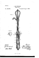
- Figure l represents a vertical section through a pump having my improvement applied
- Fig. 2 represents a plan View of the perforated diaphragm upon which the inner cylinder is formed and from which it is pendent.
- A indicates the pump stock or tube, to the upper end of which the usual air-chamber with its spout and the appliances for operating the pump may be applied in any usual or preferred manner.
- the lower end of the tube A is screw-threaded to receive the upper end of a perforated and internallythreaded cup-shaped (inverted) casting B, which is secured to the tube A by being screwed thereon, as shown.
- the bore of the ⁇ cast-ing is enlarged at its lower end at b to receive a diaphragm C, said enlargement 0f the bore terminating in an annular shoulder b', against whichthe diaphragm C rests and is clamped, as will appear.
- the casting is screwthreaded internally to receive the upper screw-threaded end of the pump-cylinder D or of the upper section thereof, as shown.
- the diaphragm C has the inner cylinder E formed upon or cast in one piece with it on its lower side or face and pendent from it, so that when the diaphragm C is placed within the enlarged bore 0r socket b, and the cylinder-section D is screwed into place in said socket, the diaphragm rests upon and is held by said cylinder, and in turn upholds the inner cylinder E suspended within the outer main cylinder.
- a gasket c may be inter- Aposed between the cylinder.
- the arrangement is such that when the cylinder D is screwed to place in the casting B the diaphragm will be snugly clamped against the shoulder b', thereby effectually preventing relative movement of the cylinders D and E and holding the latter iirmly in place.
- An annular iiange or collar E is formed on the upper face of the diaphragm C, around the central perforation therein, and this iiange is internally screw-threaded to engage the lower end of a tube G, in which the pumprod H works, the latter being guided and steadied in its movements and kept from contact with the water thereby.
- the upper end of this tube G is secured to the head or top of the pump or air-chamber, and the forcepiston and lift-bucket I and I are connected to and operated by the rod H in the usual manner.
- the diaphragm C and cylinder E being connected and supported independently of the tube G, as described, the latter may be dispensed with, if desired; but for the purpose of protecting the pump-rod from moisture and consequent danger of having its operation interfered with byr frost in cold weather, it is preferred to use a pendent tube roo of suiiicient length for that purpose; but it is not necessary that it should extend down to and be connected with the diaphragm.
- the diaphragm C is provided with one or more radial perforations c', Which extend from its central perforation to t-he periphery of said diaphragm, Vconnecting at the latter point with an annular groove b2 in the casting or coupling B, and from which perforations b3 extend outward through the latter, as shown, for affording a vent to Water which may get above the piston I in the cylinder E.
- the piston I Works Within the cylinder E, and for the purpose of protecting the latter from rust, which in time would interfere with the Working of the piston and impair the operation ot the pump, said cylinder has a lining, of porcelain or other vitreous enamel a, applied to its inner surface, in connection with which the piston I Works, said enamel effectually protecting the cylinder and greatly increasing its durability as compared with the ordinary construction of said cylinder.
Description
(No Model.)
vJ. M. WINGBR.
. FORGE PUMP. No. 408.564.
N. PETERS. Phmn-Lnnugnpm wasmrmmnlr;
UNITED STATES .PA-TENT OEEICE.
JOHN M. IVI-NGER, OF SPRINGFIELD, ASSIGNOR TO THE SUPERIOR MACHINE COMPANY, OF NEW CARLISLE, OHIO. i
FORCE-PUMP.
` SPECIFICATION forming part of Letters Patent No. 408,564, dated August 6, 1889.
Application iiled October 8, 1888. Serial No. 287,488. (No model.)
T0 all whom, it may concern:
Be it known that I, JOHN M. WINGER, of Springfield, county of Clark, and State of Ohio, have invented a new and useful Improvement in Force-Pumps, of which the following is a full, clear, and exact description, reference being` had to the accompanying drawings, making part of this specification.
My invention relates to that class of pumps in which an inner cylinder is employed, suspended within the main or outer cylinder and within which a force piston or bucket is arranged to operate in conjunction with the usual plunger or piston operating the main pump-cylinder, and, more particularly, to the construction of said inner suspended cylinder and its diaphragm and the arrangement of the latter in connection with the outer main cylinder, whereby it is made to support and give vent to the inner cylinder, as hereinafter described and claimed.
In the accompanying drawings, Figure l represents a vertical section through a pump having my improvement applied, and Fig. 2 represents a plan View of the perforated diaphragm upon which the inner cylinder is formed and from which it is pendent.
The pump shown inthe drawings, in its organization or general construction and arrangement of the parts, is similar to that shown in Letters Patent No. 305,955, granted to Paxson and Cotteld, September 30, 1884, and need not therefore be described in detail further than is necessary to an understanding of my improvement.
A indicates the pump stock or tube, to the upper end of which the usual air-chamber with its spout and the appliances for operating the pump may be applied in any usual or preferred manner. The lower end of the tube A is screw-threaded to receive the upper end of a perforated and internallythreaded cup-shaped (inverted) casting B, which is secured to the tube A by being screwed thereon, as shown. The bore of the `cast-ing is enlarged at its lower end at b to receive a diaphragm C, said enlargement 0f the bore terminating in an annular shoulder b', against whichthe diaphragm C rests and is clamped, as will appear. At the lower end of this enlarged bore the casting is screwthreaded internally to receive the upper screw-threaded end of the pump-cylinder D or of the upper section thereof, as shown.
The diaphragm C has the inner cylinder E formed upon or cast in one piece with it on its lower side or face and pendent from it, so that when the diaphragm C is placed within the enlarged bore 0r socket b, and the cylinder-section D is screwed into place in said socket, the diaphragm rests upon and is held by said cylinder, and in turn upholds the inner cylinder E suspended within the outer main cylinder. A gasket c may be inter- Aposed between the cylinder. D and the diaphragm C, and preferably the arrangement is such that when the cylinder D is screwed to place in the casting B the diaphragm will be snugly clamped against the shoulder b', thereby effectually preventing relative movement of the cylinders D and E and holding the latter iirmly in place.
By the construction of the diaphragm and inner cylinder in one piece or casting,` as described, the expensive fittings heretofore required are dispensed with, all liability of accidental displacement of the parts is avoided, and the cost of manufacture materially reduced.
An annular iiange or collar E is formed on the upper face of the diaphragm C, around the central perforation therein, and this iiange is internally screw-threaded to engage the lower end of a tube G, in which the pumprod H works, the latter being guided and steadied in its movements and kept from contact with the water thereby. The upper end of this tube G is secured to the head or top of the pump or air-chamber, and the forcepiston and lift-bucket I and I are connected to and operated by the rod H in the usual manner.
The diaphragm C and cylinder E being connected and supported independently of the tube G, as described, the latter may be dispensed with, if desired; but for the purpose of protecting the pump-rod from moisture and consequent danger of having its operation interfered with byr frost in cold weather, it is preferred to use a pendent tube roo of suiiicient length for that purpose; but it is not necessary that it should extend down to and be connected with the diaphragm.
The diaphragm C is provided with one or more radial perforations c', Which extend from its central perforation to t-he periphery of said diaphragm, Vconnecting at the latter point with an annular groove b2 in the casting or coupling B, and from which perforations b3 extend outward through the latter, as shown, for affording a vent to Water which may get above the piston I in the cylinder E.
The piston I Works Within the cylinder E, and for the purpose of protecting the latter from rust, which in time would interfere with the Working of the piston and impair the operation ot the pump, said cylinder has a lining, of porcelain or other vitreous enamel a, applied to its inner surface, in connection with which the piston I Works, said enamel effectually protecting the cylinder and greatly increasing its durability as compared with the ordinary construction of said cylinder.
Having no` described my invent-ion, What I claim as new, and desire to secure by Letters Patent, is-
1. The combination, with the pump tube or stock A and the outer main cylinder D, of the cup-shaped casting B, provided at top and bottom with internal screwthreads for receiving the stock A and cylinder D, and
the inner cylinder E, diaphragm C, and scre\v threaded flange F, formed in one piece and arranged substantially as described.
2. The pump-stock A, the outer main cylinder D, and the internally-screw threaded coupling B, provided with the annular groove b2, for the reception of and in combination with the diaphragm C, and its integrallyformed inner cylinder E and screw-threaded fiange F, all arranged to operate as specified.
3. The pump-stock A, the outer main cylinder D, and the internally-threaded coupling B, provided with the annular `groove or recess b2, for the reception of and in combination with the diaphragm C, whose diameter is less than the diametrical measurement of the groove or recess b2, whereby space is provided between the periphery of the diaphragm C and the Wall of the groove or recess b2 for the passage of Water, said diaphragm being provided with the perforation or vent c', and having the integrally-formed inner cylinder E, substantially as and for the purpose specified.
In testimony whereof I have hereunto set my hand this 30th day of September, A. D. 1888.
JOHN M. IVINGER.
lVitnesscs:
ROBERT C. RoDGERs, Guo. W. RoBIsoN.
Publications (1)
| Publication Number | Publication Date |
|---|---|
| US408564A true US408564A (en) | 1889-08-06 |
Family
ID=2477502
Family Applications (1)
| Application Number | Title | Priority Date | Filing Date |
|---|---|---|---|
| US408564D Expired - Lifetime US408564A (en) | Force-pump |
Country Status (1)
| Country | Link |
|---|---|
| US (1) | US408564A (en) |
-
0
- US US408564D patent/US408564A/en not_active Expired - Lifetime
Similar Documents
| Publication | Publication Date | Title |
|---|---|---|
| US408564A (en) | Force-pump | |
| US986122A (en) | Valve mechanism for air-compressors. | |
| US338609A (en) | Valve-seat | |
| US1022556A (en) | Pump. | |
| US460223A (en) | Clayton p | |
| US394088A (en) | tylee | |
| US968029A (en) | Pump construction. | |
| US1212294A (en) | Retaining-cup. | |
| US372888A (en) | Eoscoe bean | |
| US262845A (en) | Pump-plunger | |
| US118859A (en) | Improvement in pumps | |
| US38444A (en) | Improvement in pumps | |
| US259394A (en) | Deep-well pump | |
| US179332A (en) | Improvement in pumps | |
| US403962A (en) | Samuel t | |
| US145895A (en) | Improvement in linings for pump-cylinders | |
| US333808A (en) | Double-acting pump | |
| US567279A (en) | Valve-guard | |
| US620041A (en) | Double-acting pump | |
| US742828A (en) | Pump mechanism. | |
| US548834A (en) | Stanley b | |
| US204280A (en) | Improvement in pumps | |
| US949423A (en) | Pump. | |
| US188977A (en) | Improvement in force-pumps | |
| USRE4678E (en) | Improvement in pumps |